Table of Contents
Advertisement
Quick Links
Advertisement
Table of Contents

Related Manuals for BYD B-Box H


Summary of Contents for BYD B-Box H
- Page 1 B-Box HV Installation Guidance B-Box H Installation Guidance 27th_Sep.2017 1 / 22...
-
Page 2: Table Of Contents
WITCH ON THE NVERTER SET UP THE INVERTER PARAMETER ..........................21 8.4 S WITCH ON THE AIR SWITCH OF THE BATTERY AND THE SYSTEM CAN WORK NORMALLY 9 SYSTEM SHUTDOWN PROCEDURE ........................................ 22 Website of installation video:http://www.byd.com/energy/b-box-25.htm 2 / 22... -
Page 3: Safety
All work relating to electrical connections of the system shall be carried out by qualified personnel only. All operations of B-Box H relating to electrical connection must be done by professionals. B-Box H provides a safe source of electric energy when operated as designed. -
Page 4: Product Overview
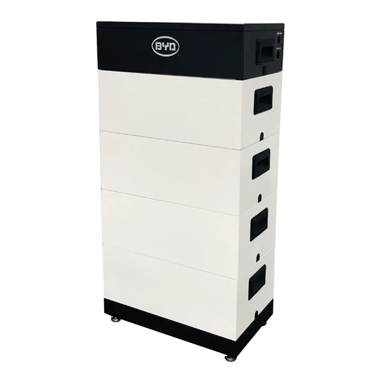
1 Product Overview B-Box H is the abbreviation of high-voltage battery box, with the operating voltage range within 200~500V. It is applied to the household energy storage field and works together with high-voltage inverter to realize energy storage and release. Each set of battery of the system... - Page 5 B-Box HV Installation Guidance Position Designation Base B-Plus-H 5 / 22...
-
Page 6: Bcu Introduction
B-Box HV Installation Guidance 2 BCU Introduction The battery management and control part, which contains BCU and charge-discharge relay, and connected to the battery modules underneath and to inverter or BMU above. Position Designation Left side terminals Ethernet CAN (Inverter) Grounded Position Designation... - Page 7 B-Box HV Installation Guidance Definition of BCU Functional Interfaces Interface Name Description The system positive terminal, connected to the positive terminal of battery interface of inverter. The system negative terminal, connected to the negative terminal of battery interface of inverter. Grounding terminal, connected to the ground.
-
Page 8: Description Of B-Plus-H Interface And Terminal
B-Box HV Installation Guidance 3 Description of B-Plus-H Interface and Terminal The battery module provides energy and sends the information about the cell voltage and cell temperature in the battery module to the upper-layer BCU. Pluggable terminal on the battery Side-lock, used to lock the upper and lower batteries. -
Page 9: Box Hv Inverter Configuration List
B-Box HV Installation Guidance 4 B-Box HV Inverter Configuration List 4.1 B-Box HV Configuration List with SMA Sunny Boy Storage 1 Phase on Grid Inverter Type B-Plus-H quantity BCU quantity SBS 2.5 5 ~ 9 4.2 B-Box HV Configuration List with Kostal Piko 3 Phase on Grid B-Plus-H quantity BCU quantity... -
Page 10: Packing Information And System Structure Configuration List
B-Box HV Installation Guidance e) After installation, ensure the positive and negative terminals of BCU and inverter are connected correctly. The installation place shall be on a flat ground, without accumulated water. 5.2 Packing Information and System Structure Configuration List The battery, BCU+ base are packed in separate carton. -
Page 11: Installation Tools
B-Box HV Installation Guidance 5.4 Installation Tools Crimping pliers Crimping pliers Screwdriver suit Adjustable wrench Diagonal cutters Inner hexagon spanner 5.5 Personal Protection Equipment 11 / 22... -
Page 12: Installation Of Single System
B-Box HV Installation Guidance 6 Installation of Single System Step 1: open the battery package; Battery Pearl wool Pearl wool Plastic bag Carton 12 / 22... - Page 13 B-Box HV Installation Guidance Step 2: Take out the BCU & Base, BCU & Base are locked and packed in the same box (the method is the same as the first step); unlock the lock with inner hexagon spanner, separate the BCU and the base. Tool: Inner hexagon spanner BCU &...
- Page 14 B-Box HV Installation Guidance Step 3: adjust the support of the base; drill 4 holes on the wall with M6 expansion bolt (the distance between ground and the bottom holes depends on different module numbers, please refer to picture below; the distance between the bottom two holes and upper two holes is 80mm; the distance between the right two holes and left two holes is 200mm;...
- Page 15 B-Box HV Installation Guidance Serial number 786.1 906.1 1026.1 1146.1 1266.1 Bottom hole height(mm) N Remark: The bracket are needed to replaced by another proposal due to hard to install, so it should be permitted to do not install the bracket untill we provide the new bracket.
- Page 16 B-Box HV Installation Guidance Step 4: Install the batteries (5pcs~8pcs), and lock the batteries with the base, ; then install BCU, and lock the batteries with BCU; the installation is completed. Tool: Inner hexagon spanner Stack up the B-Plus-H according to the actual quantity required, and lock the side lock tightly.
- Page 17 B-Box HV Installation Guidance Fixing arch Install the Fixing plate BCU fixing Fit in the arch into the BCU, lock fixing plate. the side lock, installation finish. 17 / 22...
-
Page 18: Connecting With The Sbs Inverter
B-Box HV Installation Guidance 7 Connecting with the SBS Inverter Tools: Cross screwdriver, with torque force: 25± 2.5Nm. Open the top cover of the BCU. Connect the power cable: get the positive and negative cables through the PG head, connect them into BCU case, and then install them onto the positive and negative terminals respectively. - Page 19 B-Box HV Installation Guidance Ethernet cable WLAN Caution : 1 Before connect operation, please make sure of the air switch is on “OFF”. 2 Please do not reverse connect P+ and P-. 3 Please make sure of reliable grounding. 19 / 22...
-
Page 20: System Boot
Caution: Please do not start inverter. 8.2 Software update and system setting Please download the software and connect system with PC by WIFI, operate following the document of “B-Box H Update and initial setting”. Caution: Please update first. 8.3 Switch on the Inverter, set up the inverter parameter. -
Page 21: Switch On The Air Switch Of The Battery, And The System Can Work Normally
B-Box HV Installation Guidance System nominal capacity System nominal capacity 8.4 Switch on the air switch of the battery, and the system can work normally. 21 / 22... -
Page 22: System Shutdown Procedure
B-Box HV Installation Guidance 9 System Shutdown procedure Note: Please power off the inverter before shutting down the system. After the system is shut down, check the following items: The inverter is powered off. The battery system is switch off. 22 / 22...
Need help?
Do you have a question about the B-Box H and is the answer not in the manual?
Questions and answers