Table of Contents
Advertisement
Quick Links
3303M11
I
n
t
r
i
n
s
i
c
a
l
l
y
S
a
f
e
E
x
p
l
o
s
i
o
n
-
P
r
o
o
f
E
l
e
c
t
r
o
n
i
c
S
c
a
l
e
I
n
t
r
i
n
s
i
c
a
l
l
y
S
a
f
e
E
x
p
l
o
s
i
o
n
-
P
r
o
o
f
E
l
e
c
t
r
o
n
i
c
S
c
a
l
e
GZII-(B)CEx
Series
Operation Manual
Instructions
To ensure safe and proper use of the scale, please read this manual
carefully.
After reading this manual, store it in a safe place near the scale, so
you can review it as needed.
SHINKO DENSHI CO., LTD.
Manual_GZ_V1
Advertisement
Table of Contents

Related Manuals for Vibra GZII-CEx Series


Summary of Contents for Vibra GZII-CEx Series
- Page 1 3303M11 GZII-(B)CEx Series Operation Manual Instructions To ensure safe and proper use of the scale, please read this manual carefully. After reading this manual, store it in a safe place near the scale, so you can review it as needed. SHINKO DENSHI CO., LTD.
- Page 2 CAUTION Thank you for purchasing the GZII Series Intrinsically Safe Explosion-Proof ElectronicScale. Use apparatus correctly according to Operation manual, otherwise it will cause dangerous for life and cause disaster like factory explosion by the gas ignition. In the case of improper use, no safety shall be guaranteed. Before operation, the law and technical standard of the country where apparatus is operated shall be confirmed whether target gas suits the gas classification, otherwise it will be dangerous for life and cause disaster like factory explosion by the gas ignition.
- Page 3 IECEx CERTIFICATE Certificate No.: IECEx KEM 08.0016 Type of Protection: ia Marking: Ex ia II B T4 STANDARS: IEC 60079-0:2004 Edition: 4.0 IEC 60079-11:2006 Edition: 5 Test Report: NL/KEM/ExTR08.0012/00 EQUIPMENT: Temperature Range: +5°C to +35°C POWER SUPPLY: GZ II-B, EZ II-B and EZ-B Series: 1.5 V Manganese dry cell batteries National/Panasonic Type R14P (NR).
-
Page 4: Table Of Contents
Conditions and Cautions for Limit Function Installation 1 Select the Limit function ....20, 21 1 Conditions of Installation (for the 2 Setting by Weighing Actual Samples . 22, 23 Explosion-Proof Type)......1, 2 3 Setting by Entering Values ....24, 25 2 Cautions about Installing the Scale .. -
Page 5: Conditions Of Installation (For The Explosion-Proof Type)
Conditions of Installation (for the Explosion-Proof Type) Power supply box type 危険場所 Non-hazardous area 非危険場所 Hazardous area Metal connector メタルコネクタ Metal connector メタルコネクタ 出力電圧 +12V Output voltage: +12 V Power supply 入力 電源回路 Input power circuit 電源 Power supply voltage: 重量測定回路... - Page 6 Conditions and Cautions for Installation Dry-cell battery type Hazardous area Metal connector Weight measurement circuit Weight display GZBDS P-1 board Power supply circuit Battery box 6 R14P cell batteries connected in series. Case grounding Case grounding Dedicated cable (scale cable) 5-core shielded cable, Cross section: 0.5 mm Inductance of the dedicated cable for the scale (scale cable):...
-
Page 7: Cautions About Installing The Scale
Conditions and Cautions for Installation Cautions about Installing the Scale 1. Be sure to replace dry cell batteries of the dry-cell battery type scale in a non-hazardous area. The type of the cell batteries is limited to C-size red manganese batteries (type: R14P from National / Panasonic). -
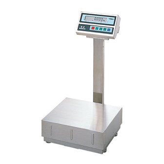
Page 8: Outer View
Outer View Small-sized scale (2 kg to 12 kg) GZ II-(B)2000CEx GZ II-(B)6000CEx to (B)12KCEx Display Display Pole Pole Calibration knob Calibration knob Adjuster Adjuster Power supply box Medium-sized scale (30kg to 60kg) (Provided for the power supply box type only) GZ II-(B)30KCEx to 60KCEx Locations of the connectors (pin board) for output options... -
Page 9: Details Of The Panel
Names and Functions of the Component Parts Details of the Panel • Display of judgment result of the • Display of the sum The mark “ ” lights and limit function the sum (accumulation) of The judgment result is indicated by the addition is displayed. -
Page 10: Checking Supplied Items
Checking Supplied Items Check the supplied items of the model you purchased and the accessories of the power supply part shown in the following table. If any items are missing or broken, please contact immediately the retailer of the scale or our Sales Office. Small-sized model Accessory Medium-sized model... -
Page 11: Cautions About Installation
Installation Accessories of the Power Supply Unit Power supply box type Dry-cell battery type ×1 ×6 (1) Power supply box (1) C-size manganese dry-cell battery (R14P) ※R14P(NR):National / Panasonic with spare fuses ×1 ×1 (2) Power supply cable (5 m) (2) Small wrench (Subtense: 2 mm) Cautions about Installation... -
Page 12: Assembling A Small-Sized Scale
Installation Assembling a Small-Sized Scale Attach the pole. Install the accessory pole to the rear guide with the pole knob. Pole Unless the pole fits the guide correctly or the pole knob screw is not tightened Pole fixing knob enough, the display may tilt or flicker. Pole guide Attach the Pass the scale cable in the pole and attach... -
Page 13: Assembling A Medium-Sized Scale
Installation Assembling a Medium-Sized Scale If you do not use the pole, remove the display stay and assemble the scale as indicated on the next page. Attach the pole base. Base guide Install the accessory pole base to the base guide at the bottom of the scale with the supplied large wrench. - Page 14 Installation Attach the pan. Place the pan on the scale.
-
Page 15: Horizontal Adjustment Of The Scale
Installation Horizontal Adjustment of the Scale ◆GZ II-(B)2000CEx to (B)12KCEx ◆GZ II-(B)30KCEx to (B)60KCEx Level Adjuster Adjuster Provided in the four corners. Provided in the four corners. Level Rotate the four adjusters until the bubble in the level fits within the blue circle. Blue Press the four corners to check for rattling of circle... -
Page 16: Installation Of The Power Supply Box
Installation Installation of the Power Supply Box This section applies to the scale of the power supply box type. Jump to the next section when you use a dry-cell battery type. First finish the cable installation work. Be sure to have the specified gas flow prevention work performed for the lead-in section of the cable because the section is laid between the hazardous area and the non-hazardous area. -
Page 17: How To Replace Batteries
Installation How to Replace Batteries This section applies to the scale of the dry-cell battery type. Return to the previous section when you use a power supply box type. Be sure to replace batteries in a non-hazardous area. Remove the battery box. Display Loosen the screw in the rear of the display Scale cable... -
Page 18: Basic Operation Of The Scale
Getting Started and Checking Operation As for the power-supply box type, first turn on the power switch in the power supply box. Turn the power on. Press the key on the panel, and all the indicators light up, showing that the instrument is operating. -
Page 19: Taring And Weighing
Basic Operation of the Scale Taring and Weighing Taring operation Place the tare (container) on the pan and The weight of the tare (container) is displayed. press the key, and the readout changes Place the tare (container) on the pan. ⇒... -
Page 20: Notes On Handling The Scale
Basic Operation of the Scale Notes on Handling the Scale Load or unload samples on the scale carefully. Do not permit any material to be inserted beneath Do not apply mechanical shocks to the the pan. instrument. Do not leave a load over the weighing capacity Calibration is recommended after installation or relocation or when the scale is used after being on the scale (“”... -
Page 21: Addition Function
The addition function sums the results of weighing samples subdivided into several parts. This function is convenient when the total weight is checked at the time of filling, blending, or consecutive weighing small quantities. Select the Addition function Press and hold the key for approximately Call the function. -
Page 22: Procedure For Making Addition And Displaying The Sum
Addition Function Procedure for Making Addition and Displaying the Sum Weigh the samples. Place samples on the scale for weighing. The net weight is measured. Place the sample in the container. TOTAL Add the weight of the samples. The result of the addition is Press the key. - Page 23 Addition Function Add the weight of the samples. Press the key. The result of the addition is displayed. The sum is displayed together with the “ ” mark for temporary display of the addition TOTAL result. After approximately 3 seconds, the original display is resumed.
-
Page 24: Limit Function
The limit function allows the scale to store the upper and lower limit values for judgment of whether the measurement result falls within the limit values. This function is very convenient for identifying defective items or weighing predetermined quantities. Methods of Entering Limit Values The following two methods are available and they can be used alone or in combination. - Page 25 Limit Function Select a condition. Press the key, and the next item (condition) is displayed. Function Selection Select a condition. Press the key, and the rightmost value changes. Then select the value that you want to set. Display: Condition ...
-
Page 26: Setting By Weighing Actual Samples
Limit Function Setting by Weighing Actual Samples If zero is not shown in the display, press the key to make the display show zero before starting the procedure. If a container is used, perform the taring process to make the display show zero. Start setting the limit values. -
Page 27: Setting By Weighing Actual Samples
Limit Function Setting is over. Press the key, and the setting is saved and “ ” is displayed. Setting is over. Save the setting. Press the key again, and the setting process is terminated and the weight display mode is resumed. -
Page 28: Setting By Entering Values
Limit Function Setting by Entering Values Start setting the limit values. Press hold Start entering the lower limit value. Call the setting. approximately 3 seconds. When “ ” is displayed, release the finger. Now the lower limit value can be set. -
Page 29: Setting By Entering Values
Limit Function Setting of the lower limit value is over. When the entering of the lower limit value Setting of the lower limit value is over. The set value is displayed. press the key. is over, The display disappears temporarily. When the lower limit value is saved, the The display stays out while display blinks. -
Page 30: Functions
This scale is provided with the functions shown in the table below. These functions can be adjusted according to ⇒ your work conditions. Refer to “Checking the Set Value” on page 28 and “Changing the Setting” on page 29. Functions and How They Work 2.1 Basic Functions * Shaded parts indicate factory default settings. - Page 31 Functions 2.2 Details of the Limit Function When you select the Additional Function “ ,” the following functional items are displayed before the Autozero function. Functional item Display Description Always judge. (Judgment is also made when the scale is unstable.) Condition ...
-
Page 32: Checking The Set Value
Functions Checking the Set Value Call the function. Press hold approximately 4 seconds. When Function Call Function Display “ ” is displayed, release the finger. Now the function setting mode is assumed Press and hold. -
Page 33: Change The Setting
Functions Change the Setting Call the function. Press hold approximately 4 seconds. When Function Call Function Display “ ” is displayed, release the finger. Now the function setting mode is assumed Press and hold. - Page 34 The electronic scale is always influenced by gravity (G). The gravity changes depending on the geographical position and altitude above sea level, so the scale must be calibrated where it is installed. Calibration is also needed when an extended period of time has elapsed after installation or correct readings cannot be given.
-
Page 35: Calibration Of The Scale
Calibration of the Scale Setting of the capacity point is over. When calibration of capacity point is over, Save the span value. “ ” is displayed. Press the key, and the span value is saved. -
Page 36: Troubleshooting
Symptom Cause Action to take The limit function * The limit function is not selected. 20P: Select the function. does not work. * A limit value is not entered. 24P: Perform the setting procedure. * The entered limit value is invalid. 24P: Check your operation. -
Page 37: Standard Specifications
Common Specifications 1. Explosion proof structure ......Exia II BT4 2. Precision class ..........Class II 3. Measurement method ........Dielectric system (tuning fork system) 4. Taring range..........Up to weighing capacity 5. Display ............LCD of up to 7 digits (character height = 17 mm, character width = 9 mm, with a 5-degree slant) 6. -
Page 38: Configuration Of Each Model
Standard Specifications Configuration of Each Model 2-1. Power Supply Box Type Weighing Scale interval Length capacity/minimum (e)/actual Dimension Empty Type Model Class of scale measurable scale interval of pan weight cable weight Approx. φ170 GZ II-2000CEx 2000 g/0.5 g 0.1 g/0.01 g 8 kg Small-sized model... - Page 39 Standard Specifications SHINKO DENSHI CO., LTD. HEAD OFFICE: 3-9-11 YUSHIMA, BUNKYO-KU, TOKYO 113-0034, JAPAN TEL: 81-3-3835-4577 E-MAIL: shinko@vibra.co.jp FAX: 81-3-5181-6066 URL: http://www.vibra.co.jp/ TSUKUBA PLANT: 4219-71 TAKASAI, SHIMOTSUMA, IBARAKI, 304-0031, JAPAN TEL: 81-296-43-2001 FAX: 81-296-43-2130...
Need help?
Do you have a question about the GZII-CEx Series and is the answer not in the manual?
Questions and answers