Table of Contents
Advertisement
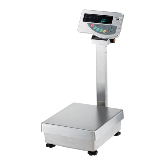
High-Precision, Advanced Tuning Fork Balance
HJ-KCE/HJR-KCE Series
%Ï To ensure safe and proper use of the balance, please read this
manual carefully.
%Ï After reading this manual, store it in a safe place near the
balance, so you can review it as needed.
Operation Manual
IMPORTANT
SHINKO DENSHI CO., LTD.
220011M01
Advertisement
Table of Contents

Subscribe to Our Youtube Channel
Related Manuals for Vibra HJ-KCE series


Summary of Contents for Vibra HJ-KCE series
- Page 1 220011M01 High-Precision, Advanced Tuning Fork Balance HJ-KCE/HJR-KCE Series Operation Manual IMPORTANT %Ï To ensure safe and proper use of the balance, please read this manual carefully. %Ï After reading this manual, store it in a safe place near the balance, so you can review it as needed. ...
- Page 2 PREFACE Thank you for purchasing an HJ-KCE/HJR-KCE Series electronic balance. This balance is equipped with a high precision mechanism. It provides parts counting, percentage weighing, and limit functions helpful in weighing a certain amount, and has various other functions. This advanced balance employs a user-friendly program, and the key arrangement is also easy to operate.
-
Page 3: Table Of Contents
Contents 1 Precautions Relating to Use......2 10 Date and Time Setup........37 2 Names of Component Parts ......5 11 Various Functions 11.1 Auto Sleep Function....... 38 3 Installation of the Balance and Operation 11.2 Auto Power Off Function......38 Check 11.3 Set Unit Function........ -
Page 4: Precautions Relating To Use
1 Precautions Relating to Use This Section “Precautions Relating to Use” sets forth precautionary notes that the user should observe in order to prevent physical injury to the user and/or damage to property. The nature of problems that may result in the event of improper operation, and consequential effects on the quality and performance of the balance, are indicated under the two categories of “Caution”... - Page 5 Do not place the balance on an unstable base or use the balance in a location where it may be subjected to shock. · The loaded sample may fall off the measurement Do Not Use pan. · Accurate measurement may be rendered impossible.
- Page 6 Avoid applying excess force or impact to the balance. · Place the sample to be measured on the balance carefully to prevent breakage or malfunction. Do Not Apply Force Do not use the balance in a location were it may be subjected to abrupt changes in ambient temperature or humidity.
-
Page 7: Names Of Component Parts
2 Names of Component Parts Main Unit 2.1.1 Pole type (HJ[R]-KCE, HJ[R]-KDCE) Display Operation key Pole Adjuster (4) 2.1.2 Separate type (HJ[R]-KSCE, HJ[R]-KDSCE) Level 2.1.3 Underside (common to the pole and separate types) Cover for openings for under weighing (The hook for hanging is an option. For more information, refer to the instruction manual for the hook for hanging.) * Close the cover to protect against dust and water... - Page 8 Display (Backside) * Common to the separate and pole types. 2.2.1 Backside Balance cable Connector cover Jack for the AC adapter Screws to fix the connector cover Knob (Used to adjust the angle of the display) 2.2.2 Output connectors (when the connector cover is removed) To remove the connector cover, unfasten the four screws fixing the cover.
- Page 9 Displayed Signs and Operation Keys 2.3.1 Displayed signs Display Description Kilogram, gram ®0¬ Zero point Minus Tare sign Gross weight Indicates stable balance (If this light is off, the balance is unstable.) Indicates that the accumulation function is enabled, and withstands additional load.
- Page 10 2.3.2 Operation keys and their functions Operation key Function On/Off key Turns the balance on or off. Starts output. Print key Also used to cancel the setting of a date and time. [Short press] Starts the setting of a count or a percent. Set key [Long press] Starts the setting of a limit value when the limit function is enabled.
-
Page 11: Installation Of The Balance And Operation Check
3 Installation of the Balance and Operation Check Installation 3.1.1 Procedure for installing the pole type balance Lift the pan, and slide it backward. Loosen the two knobs in the lower part of the pole. Insert the pole into the balance so that the cable fits in the groove. Check that the supporting boards are hooked on the bottom of the cable housing. - Page 12 3.1.2 Procedure for installing the separate type balance To use the display and the balance separately from each other Lift the pan, and slide it backward. Slightly open both sides of the cable cover, and mount it vertically in the cable housing. ...
-
Page 13: Operation Check
Operation Check 3.2.1 Turn the power on and off and check the display Connect the AC adapter. The balance enters standby mode, and the Stand by lamp (LED) lights up. Press the On/Off key. When the display lights up, check it for missing signs. When an object is lying on the pan, the blinking “on 0”... - Page 14 Weigh additional samples 4 Reset the display to 0. Press the Zero/Tare key. ! ’ 0 ! • 00 000 0 0000 Net 00 The gross weight of the sample on the pan is reset to 00000000000 5 Put an additional sample on the balance. The weight of the additional sample is displayed.
- Page 15 Hints The following description applies commonly to the weighing machine, parts counting, percentage weighing, and unit converting functions. A small amount of current is still flowing after the balance is turned off. In a standby state, the Stand by lamp (LED) is lit. When the balance is turned on, the LED goes out.
-
Page 16: Function
4 Function 1 Setting and Check 1. Call Function 1. Press and hold down the Function key until a series of dots [] is displayed. Now you can set Function 1. The first setting item is ... -
Page 17: Description Of Function 1
] (ct) A star () denotes a factory setting. 1 denotes a factory setting for the HJR-KCE series, and 2 denotes a factory setting for the HJ-KCE series. 3 The HJ-KCE series does not display [ ] or [... - Page 18 Item Set Value Description None [ g ] Unit B [ kg ] ] (ct) Without auxiliary display Auxiliary display 4 With auxiliary display Disable Only HJR-62KD[S]CE and HJ-62KD[S]CE display ...
-
Page 19: Limit Function
Limit Function ] is [] or []. Displayed when Item Set Value Description Always judge (even when the balance is unstable). Condition Judge only when the balance is stable. Detect when the limit is exceeded by more than 5 divisions ... -
Page 20: Interface
Interface Displayed unless input/output is stopped in Interface of Function 1. Item Set Value Description Stop output Output continuously at all times Output continuously if stable (Stop output if unstable) Output once when the Print key is pressed (whether the ... -
Page 21: Function 2
5 Function 2 Setting and Check 1 Call Function 2. Press the Function key while holding down the Zero/Tare key. Press the Function key while holding down the Zero/Tare key. When a series of dots [] is displayed, release the key. 000000000000 0000 The display is changed to [... -
Page 22: Weighing Mode
6 Weighng Mode You can select a Weighing Mode from four types in Function 1: weighing machine, parts counting, percentage weighing, and unit converting. All the Weighing Mode support additional functions (or the accumulation function and the limit function) depending on the unit to use. Measurement Modes When you select a Weighing Mode and additional functions, you can weigh samples in different ways as shown below. -
Page 23: Parts Counting
Parts Counting The parts counting function employs an automatic memory update method, also referred to as a Self Counting System. When you put a specified number of samples on the balance, and put additional samples, the balance automatically updates the average unit weight of the samples. However, you cannot add more than three times as many samples as the first reading. - Page 24 5 Put additional samples on the balance. When you add samples, the balance updates the memory unless you add more than three times as 0 0 0 0 0 0 0 0 0 0 0 0 0 0 0 0 0 P c s many samples as the displayed number.
-
Page 25: Percentage Weighing
Percentage Weighing 6.4.1 Set a reference weight by weighing an actual sample You can make the display indicate the weight percentage (%) of a sample with respect to a reference sample weight. 1 Select the percentage weighing function. Select the percentage weighing function in Function 1 [... - Page 26 6.4.2 Set a reference weight by entering a value You can enter a reference weight in the balance, and then make the display indicate the weight percentage (%) of a sample with respect to the reference. 1 Set a reference weight. Press the Function key for a few seconds.
-
Page 27: Accumulation Function
7 Accumulation function The accumulation function allows you to find the cumulative weight of samples put on the balance one after another. All of the weighing machine, parts counting, percentage weighing, and unit converting functions support the accumulation function. To use the accumulation function, enable it in Function 1 [ ]. 1 Put samples on the balance, and read the Put samples to weigh on the balance. -
Page 28: Limit Function
8 Limit Function The limit function judges a weight based on limit values that you have stored on the balance. When one or two points are set, a dot () is displayed next to one of HI (high), OK (proper), and LO (low) to indicate the result. -
Page 29: Judge By Absolute Values
Judge by Absolute Values 8.4.1 Set two limit values by putting actual samples on the balance 1 Start the limit function. Press the Set key for a few seconds. When the display indicates [ ], release the key. The current lower limit is displayed next to [LO ]. - Page 30 8.4.2 Set two limit values by entering values 1 Start the limit function. Press the Set key until the display indicates [ ]. 000000000000 0000 0000000 The current lower limit is displayed next to [LO ]. Continuous press 2 Switch to the value input screen.
-
Page 31: Judge By Deviation Values
Judge by Deviation Values 8.5.1 Set two limit values by putting actual samples on the balance 1 Start the limit function. Press the Set key for a few seconds. When a series of dots [] is displayed, release the key. ... - Page 32 8.5.2 Set two limit values by entering values 1 Start the limit function. Press the Set key for a few seconds. When a series of dots [] is displayed, release the key. 0000000 The current reference weight blinks in the display. Continuous press 2 Switch to the value input screen.
- Page 33 Caution: The initial limit values are all zero. You can set separate limit values for the weighing machine, parts counting, percentage weighing, and unit converting functions. However, absolute values and deviation values are saved in the same storage area. So if you switch between absolute values and deviation values, limit values are deleted.
-
Page 34: Bar Graph For The 2-Point Scale
Bar Graph for the 2-point Scale You can set two points for the limit function, and display a bar graph to indicate the result in a range specified by the two points. All of the weighing machine, parts counting, percentage weighing, and unit converting functions support this function. -
Page 35: Calibrating The Balance
9 Calibrating the Balance An electronic balance, which is influenced by the acceleration of gravity, indicates different values depending on where it is used. For this reason, you should calibrate your balance every time you relocate it. You should also calibrate it after a long time of no use or when it does not indicate correct values. -
Page 36: Span Test With Built-In Weight
The Span test will be performed to find an error of measure without making Span adjustment. Please use it to investigate the error of measure. Span Test with Built-in Weight * Only supported by the HJR-KCE series 1 Set Function 1. Set Function 1 with nothing put on the pan. -
Page 37: Calibration Of Built-In Weight
Calibration of Built-in Weight * This instrument cannot be used when it is sealed. This function is only supported by the HJR-KCE series. This is a function to calibrate the built-in weight with an external weight. 1 Set Function 2. Set Function 1 with nothing put on the pan. -
Page 38: Date And Time Setup
10 Date and Time Setup 10.1 Time Setup The time is displayed with a dot []. Set the time in Hour-Minute-Second format on a 24-hour basis. 1 Display the time. Press the Function key for a few seconds. When the display is changed from [] to [], release the key. -
Page 39: Various Functions
11 Various Functions 11.1 Auto Sleep Function This is a function to turn off the display when the balance is left to stand in measurement mode for about 3 minutes. This function can only be used when the balance is operated on the AC adapter. To use the auto sleep function, enable it in Function 1 [... -
Page 40: Double Range
11.4 Double Range Function Only HJR-62KD[S]E and HJ-62KD[S]E support the double range function. This is a function to switch the minimum readability between 0.1 g and 1 g. A minimum readability of 0.1 g is used for a gross weight of 6200.9 g or lighter, and a minimum readability of 1 g is used for a gross weight of 6201 g or heavier. -
Page 41: Interval Output Function
11.8 Interval Output Function This is a function to output data at intervals. You can also output data with the current time. Set an interval in Hour-Minute-Second format. To use the interval output function, enable it in Function 1 [ ] or [ ]. 11.8.1 Set interval output 1 Call the interval function. -
Page 42: Enter An Id Number
11.9 Enter an ID Number An ID number is used when data is printed in compliance with ISO/GLP/GMP. Set an ID number when you print data. When an ID number is displayed, a dot [] and a triangle [%² ] are displayed in the upper left of the display. -
Page 43: Input/Output Functions
12. Input/Output Functions 12.1 RS232C Output 12.1.1 Connector pin numbers and functions Signal Pin No. Input/Output Function & Remarks Name Input Receiving data Output Transmitting data HIGH Output (When the balance is powered ON) Signal ground 10 20 30 40 5 60 7 0 8 0 9 D-SUB9P Male Connector: Rear Panel Caution:... - Page 44 12.1.2 Connection between the balance and a PC Sample wire connection with an IBM-PC/AT compatible machine Balance IBM-PC/AT compatible machine D-SUB9P D-SUB9P Sample wire connection with PC9801 Balance PC9801 D-SUB9P D - S U B 2 5 P T X D R X D R X D...
- Page 45 12.1.3 Interface specifications (1) Transmission system Serial transmission. Start-stop synchronization. (2) Transmission rate 1200ÿ 2400ÿ 4800ÿ 9600ÿ 19200 bps (3) Transmission codes ASCII codes (8/7 bits) (4) Signal level Compliant with EIA RS-232C. HIGH level (data logic 0) +5 – +15 V Low level (data logic 1) -5 –...
-
Page 46: Output To Peripherals
12.2 Output to Peripherals Our standard peripheral units can be connected to the balance.*1 These peripheral units include: CSP-160, CSP-240 12.2.1 Connector pin numbers and functions Signal Pin No. Input/Output Function & Remarks Name Tare setting from an EXT.TARE Input external device *2 Output Transmitting data... -
Page 47: Type Of Communication Texts
12.3 Type of Communication Texts This interface function uses the following three types of communication texts: (1) Output data Data, such as weight values, that is output from the balance to an external unit (2) Input commands Commands to control the balance from an external unit (3) Response Response that is output from the balance to an input command Caution:... - Page 48 (4) Format with 6-digit value with auxiliary scale interval that is compatible with type approval This format is composed of 15 characters, including the terminators (CR=0DH, LF=0AH). A slash “/” is inserted before the auxiliary scale interval. While the format with 6-digit value is selected, the auxiliary scale is output in this format. (5) Format with 7-digit value with auxiliary scale interval that is compatible with type approval This format is composed of 16 characters, including the terminators (CR=0DH, LF=0AH).
- Page 49 12.4.3 Numeric data 6-digit numeric format: (D1-D7: 7 characters) 7-digit numeric format: (D1-D8: 8 characters) Extended format with 7-digit value: (D1-D8: 8 characters) Format with 6-digit value with auxiliary scale interval: (D1-D7: 7 characters) Format with 7-digit value with auxiliary scale interval: (D1-D8: 8 characters) Extended format with 7-digit value with auxiliary scale interval: (D1-D8: 8 characters) D1 –...
- Page 50 12.4.5 Judgment result when the limit function is enabled (S1: 1 character) Code Description Too little (LO) 1- or 2-point scale Proper (OK) Too much (HI) Rank 1 Rank 2 3- or 4-point scale Rank 3 Rank 4 Rank 5 Cumulative value Unit weight Data type...
-
Page 51: Input Commands
12.5 Input Commands The following 7 input commands are supported: (1) Tare range command (2) Set output control command (3) Set measurement mode command (4) Request date output command (5) Request time output command (6) Set interval command (7) Span adjustment/test command 12.5.1 Procedure for transmission (1) Send an input command from an external device. - Page 52 12.5.2 Response You can select the response format from A00/Exx format and ACK/NAK format in Function 1. (1) A00/Exx format Consists of 5 characters including terminators (CR, LF). Response types Code Meaning Successful completion * Command error (when an errant command is received) (Errors other than E01) * Numeric format error...
- Page 53 12.5.3 Command format (1) Tare range (zero-setting) command Code Description Value Response A00: Successful completion E01: Command error · Set Tare E04: A tare range cannot be Range set or the zero point (SP) None · cannot be adjusted Adjust the (because of a range zero point violation or a weight...
- Page 54 12.5.4 Set measurement mode command Command Main Body Description Value Response Code character character A00: Successful Mode 1 completion Mode 2 None E01: Command Mode 3 error Mode 4 E02: (error) Measurement mode depends on the combination of the Weighng Mode and which mode is specified (mode 1, 2, 3, or 4).
- Page 55 You can select whether you want to output data in English or in Japanese (katakana) in Printed Language of Function 1 [ ]. Date format depends on the setting of Date Display in Function 1 [ ]. 12.5.6 Setting intervals Command Main Body Description Value...
- Page 56 12.5.8 Sample input commands T(SP)(CR)(LF) Set a tare weight or adjust the zero point. O1(CR)(LF) Set the balance to continuous output. O8(CR)(LF) Output data (once immediately). IA,12,34,56(CR)(LF) Set an interval of 12 hrs. 34 min. 56 sec. OA(CR)(LF) Start the interval function. DD(CR)(LF) Output the date.
-
Page 57: Use Printers
13 Use Printers 13.1 Setting up the Printer (1) Use CSP-160 or CSP-240 with the balance. (2) Set proper print functions (print control) with the balance referring to the instruction manual for your printer. The factory default of our printer is manual printing (printer control). (3) Make the baud rate and other settings compatible between the balance and the printer. -
Page 58: Output In Compliance With Iso/Glp/Gmp
14 Output in Compliance with ISO/GLP/GMP When span adjustment or a span test with the built-in weight or an external weight is completed, the results are printed. If span adjustment or a span test is not completed successfully, no data is printed. - Page 59 (3) Span test with the built-in weight Japanese (Katakana) English 1 4 1 5 1 4 1 5 0 Æ 0 ¹ 0 È 4 0 Ò 0 Ä " 0 ± ÿ | " 0 ³ 0 ¯ 0 « 0 ¿...
- Page 60 (5) Calibration of the built-in weight Japanese (Katakana) English 1 4 1 5 1 4 1 5 * 0 Ê 0 ¤ 0 Õ " 0 Õ 0 ó 0 È " 0 ¦ 0 ³ 0 ¦ 0 » 0 ¤...
-
Page 61: Operate On Batteries
15 Operate on Batteries This function can only be used with a balance equipped with optional batteries. 15.1 Specifications · Battery built in · Charge time: About 12 hours · Operation time: About 6 hours of continuous operation · Can be recharged: More than 300 times ·... -
Page 62: Troubleshooting
16 Troubleshooting * Parentheses contain a page to refer to. Symptom Cause Measures to Take · ® Ensure that the AC adapter The display indicates The AC adapter is not connected. nothing. is connected. · The batteries are exhausted. ® Recharge the batteries (page 58). - Page 63 Removing the rubber cap If the balance takes longer than usual to be stabilized, the filter of the balance may be clogged. In this case, remove the black rubber cap shown in the following figure for a quick fix. Force the cap open with a flathead screwdriver or a pair of pliers (The cap is somewhat difficult to remove to protect against dust and water).
-
Page 64: Specifications
17. Specifications 17.1 Basic Specifications Model HJR- HJR- HJR- HJR- Item 17K[S]CE 22K[S]CE 33K[S]CE 62KD[S]CE 17000 22000 33000 62000 Weighing capacity [g] Minimum capacity [g] Verification scale interval [g] 0.1(0-6.2kg) Actual scale interval [g] 1(6.2-62kg) Minimum unit weight (for parts counting) Lower weight limit (for percent balance) Switch between... - Page 65 17.2 Common Specifications ( 1) Weighing system ÿ e ÿ e ÿ e ÿ e ÿ e ÿ e ÿ e ÿ e ÿ e ÿ e ÿ e ÿ e ÿ e ÿ e ÿ e ÿ e ÿ e Tuning fork system ÿ...
-
Page 66: Conversion Table Of Units
17.3 Weighing Capacity and Minimum Units of Different Units Model 17KCE 22KCE 33KCE 62KDCE Unit_of 17KSCE 22KSCE 33KSCE 62KDSCE measurement 17000 22000 33000 62000 0.001 0.001 0.001 0.001 0.0001 0.0001 0.0001 0.0001 85000 110000 160000 310000 (ct) The view of the table Top line: Capacity Middle line:...
Need help?
Do you have a question about the HJ-KCE series and is the answer not in the manual?
Questions and answers