Table of Contents
Advertisement
Quick Links
Advertisement
Table of Contents
Troubleshooting

Subscribe to Our Youtube Channel
Related Manuals for Vibra GZ II Series


Summary of Contents for Vibra GZ II Series
- Page 1 GZ II Series Service Manual SHINKO DENSHI CO., LTD.
-
Page 2: Table Of Contents
Table of Contents Chapter 1 Appearance ....................1 Appearance of the Round Pan Type ................1 Appearance of the Square Pan Type ................1 Chapter 2 Configuration of the Electric Components ..........2 Entire Wiring Diagram....................2 Chapter 3 Troubleshooting..................4 Inspection Procedure .....................4 Quick Reference Guide for Troubleshooting ..............5 Initial Inspection ......................7 Inspection of the Electrical Components ...............8 Chapter 4... -
Page 3: Chapter 1 Appearance
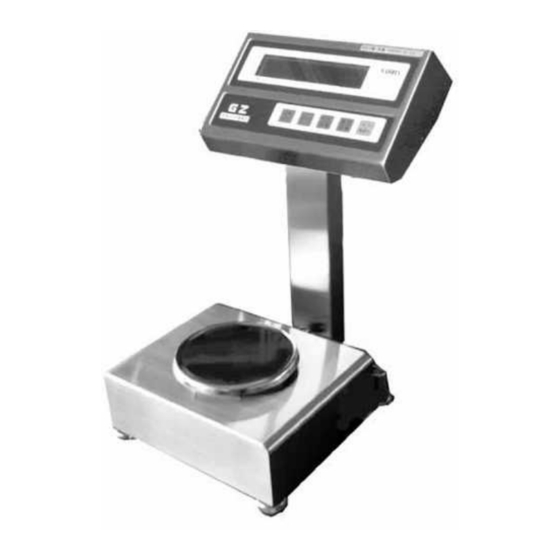
Chapter 1 Appearance 1-1 Appearance of the Round Pan Type [1000–2000 g] (Figure 1-1) 1-2 Appearance of the Square Pan Type [6000–15 kg] (Figure 1-2) -
Page 4: Chapter 2 Configuration Of The Electric Components
Chapter 2 Configuration of the Electric Components 2-1 Entire Wiring Diagram (1) Power Box Type Weighing part Mechanical part Power box GZOSC-1 board Display part GZLF board GZSW-2 board GZDSP-2 board (Figure 2-1) - Page 5 (2) Battery Type Weighing part Mechanical part GZOSC-1 board Display part Battery box GZSW-2 board GZBDSP-1 board (Figure 2-2)
-
Page 6: Chapter 3 Troubleshooting
Chapter 3 Troubleshooting 3-1 Inspection Procedure Start Is the power Is the battery Is “ box connected? box connected? “ displayed? Connect the power/battery Perform the initial box. inspection. Return to the Weight start. display mode Check the memory. Are all necessary connecters Is the displayed... -
Page 7: Quick Reference Guide For Troubleshooting
3-2 Quick Reference Guide for Troubleshooting Symptoms Probable causes Remedies 1. The GZDSP-2 (GZBDSP-1) board has 1. Replace the GZDSP-2 Noting is displayed. failed. (GZBDSP-1) board. 2. The power/battery box has failed. 2. Replace the power/battery box. 3. The connection cables inside the balance 3. - Page 8 Symptoms Probable causes Remedies 1. The mechanical section has failed. 1. Replace the mechanical Improper corner error unit. 2. Something is in contact with the pan (or 2. Check the area around pan base). the pan. 1. The GZDSP-2 (GZBDSP-1) board has 1.
-
Page 9: Initial Inspection
3-3 Initial Inspection Make sure the balance is not being affected by wind or vibration. Make sure the pan base and pan are properly in place. Make sure no foreign objects are present under the pan (or pan base). Make sure the right kind of pan is used. Make sure the balance is placed on a stable surface. -
Page 10: Inspection Of The Electrical Components
3-4 Inspection of the Electrical Components * The value of Type B is only different in CN-4. In other check points, the value is shared between Type B and Type D. Power supply voltage check CN4 - … +11 to +13 V (Type B: +6.00 to +10.32 V) In-circuit power supply voltage check CN2 - ….. - Page 11 Inspect the following parts of the GZDSP-2 board. (Figure 3-3)
- Page 12 Inspect the following parts of the GZBDSP-1 board. Connected to the battery box (Figure 3-4)
- Page 13 GZOSC-1 board check Check preparation Set up an oscilloscope and power off the balance. Touch the probe to the CN2 pins. Power: +4 to +6 V Voltage and frequency ranges of the Power: −4 to −6 V oscilloscope Square wave output (tuning fork) Square wave output (temperature) Voltage range CH1: 0.1 to 0.5 V/DIV...
-
Page 14: Chapter 4 Adjustment And Setting Procedures
Chapter 4 Adjustment and Setting Procedures 4-1 Span Adjustment (CAL) = “Set/Switch” key = “Zero/Tare” key Press the “ON/OFF” key to turn the display on. Press and hold until the display changes from “ ” to “ ,” and then release it. With no sample placed on the pan, press while pressing , and then release them at the same time. -
Page 15: Corner Error Adjustment
4-2 Corner Error Adjustment (1) Remove the unit cover (Refer to Figure 5-1). (2) Replace the pan and pan base and adjust the adjuster so that the balance is horizontal. (3) Adjust the corner error according to the following corner error adjustment table. To the GZDSP board Corner error Corner error... -
Page 16: Coefficient Data Correction And Linearity Adjustment Procedures
4-3 Coefficient Data Correction and Linearity Adjustment Procedures (1) Coefficient data correction procedure The coefficient data has changed due to static electricity or noise. Enter the coefficient data. (See the coefficient label on the Figure 4-3.) Span adjustment Performance check (2) Linearity adjustment procedure Poor linearity Enter the coefficient data. -
Page 17: How To Check (Enter) The Coefficient Data
4-4 How to Check (Enter) the Coefficient Data When the GZDSP-2 (or GZVDSP-1) board is replaced, or the coefficient data is lost due to static electricity, etc., reenter the coefficient data according to the following procedure. 1. Location of the coefficient data label * After replacing the mechanical Data sheet unit, put the data sheet for the... - Page 18 3. How to Check (Enter) the Coefficient Data “Set/Switch” key “ON/OFF” key “Zero/Tare” key Press while pressing to turn the display on. Release the keys when “ ” is displayed. After a while, the balance will be in weight display mode. At that time, press and hold and release it for a moment when “...
-
Page 19: Linearity Adjustment
4-5 Linearity Adjustment “Set/Switch” key “ON/OFF” key “Zero/Tare” key Press while pressing to turn the display on. When “ ” is displayed, release the key. After a while, the balance enters weight display mode. Press and hold until the display change from “ ”... -
Page 20: Chapter 5 Replacement Procedures
Chapter 5 Replacement Procedures 5-1 Procedure for Replacing the Mechanical Sensor Assembly How to Remove the Unit Cover (1) Power off the balance and remove the pan and pan base. (2) Remove the unit cover mounting screws A (4) with a Phillips-head screwdriver. (3) Remove the unit cover. - Page 21 The mechanical sensor assembly has failed. Replace the mechanical sensor assembly. Enter the coefficient data. (Enter data for the new mechanical unit.) Span adjustment Performance check How to Remove the Mechanical Unit (1) Remove the unit cover. (Refer to Figure 5-1) (2) Remove the tuning fork assembly cord from the GZOSC-1 board.
- Page 22 How to Install the Mechanical Unit (1) Place the mechanical unit on the chassis and secure it with the mechanical unit mounting nuts B. (2) Solder the tuning fork assembly cord to the GZOSC-1 board. (3) Check the position of the stopper to the sub link guide. (If misaligned, readjust the position by loosening screws C (2)).
-
Page 23: Procedure For Replacing The Tuning Fork Assembly
5-2 Procedure for Replacing the Tuning Fork Assembly The tuning fork assembly has failed. Replace the tuning fork assembly. Linearity adjustment Performance check... - Page 24 1. How to Remove the Tuning Fork Assembly (1) While lightly pushing the guide link downward, remove flexure mounting screw B. (2) Remove tuning fork mounting screw A. (3) Remove the tuning fork assembly. Screws A Push it down VB-1 board Screw B Tuning fork (Figure 5-5)
- Page 25 How to Adjust the Stopper Plate (1) Loosen the stopper plate mounting screws. After loosening the flexure part mounting screws of the tuning fork assembly by approximately half a turn while pushing the guide link downward, fasten them again. (Tightening torque: 2.45 N m) (2) Insert a gap gauge (0.05 t) between the stopper plate and the guide link, insert the jig rod into the hole provided on the edge of the stopper plate, and secure the mounting screws while holding the stopper plate.
-
Page 26: Procedure For Replacing The Gzdsp-2 Board
5-3 Procedure for Replacing the GZDSP-2 Board The GZDSP-2 board has failed. Replace the GZDSP-2 board. (Use the board that has been set to fit each model) Reenter the coefficient data. Span adjustment Performance check... - Page 27 How to Remove the GZDSP-2 Board (Power box type) (1) Remove screws A (2) on the backside of the GZ II display assembly and separate the assembly from the stand assembly. (2) Remove the GZ II rear case assembly mounting screws B (6). (3) Remove the CN2, CN3 and CN4 connectors on the GZDSP-2 board.
- Page 28 How to Remove the GZBDSP-1 board (Battery box type) (1) Remove screws A (2) on the backside of the GZ II display assembly and separate the assembly from the stand assembly. (2) Remove the GZ II rear case assembly mounting screws B (6). (3) Remove the CN2 and CN4 connectors and the battery box assembly connector on the GZBDSP-1 board.
-
Page 29: Procedure For Replacing The Gzosc-1 Board
5-4 Procedure for Replacing the GZOSC-1 Board How to Remove the GZOSC-1 Board (1) Remove the unit cover. (Refer to Figure 5-1) (2) Remove the tuning fork assembly cord soldered to the GZOSC-1 board. (3) Remove the CN1 connector from the GZOSC-1 board. (4) Remove the PC bracket mounting screws A (2). -
Page 30: Procedure For Replacing The Gzlf Board
5-5 Procedure for Replacing the GZLF Board How to Remove the GZLF Board (1) Remove the GZ II rear case assembly. (Refer to Figure 5-7) (2) Remove GZLF board mounting screws A (2), metal connector mounting screws B (4), and ground wire mounting screw C (1). Screws B Screw C GZLF board... -
Page 31: Chapter 6 Replacement Procedures For Options
Chapter 6 Replacement Procedures for Options 6-1 Procedure for Replacing the Insulating Barrier (1) Remove barrier cover fixing screws A (2) from the power box. (2) Remove the cables from the insulating barrier terminals. (3) Loosen the screw of one side of the fixture and replace the insulating barrier. (4) Connect barrier communication cord L to terminal 3P and the barrier power cord to (No.10 = brown, No. -
Page 32: Procedure For Replacing The Gzjp Board
6-2 Procedure for Replacing the GZJP Board (1) Remove IS box cover fixing screws B (4) from the power box. (2) Remove the connector (CN4) of the GZJP board and the connector (CN7) of the GZPS board. (3) Remove fixing screws C from the GZJP board and replace it. (4) Connect the CN3 of the GZJP board to the CN7 of the GZPS board, and connect the RS232 power cords to the CN4 and CN1 of the GZJP and GZPS boards, respectively. -
Page 33: Procedure For Replacing The Gz Printer Output (R1)
6-3 Procedure for Replacing the GZ Printer Output (R1) (1) Remove IS box cover fixing screws B (4) from the power box. (Refer to Figure 6-4) (2) Remove GZ printer cord assembly fixing screws A (2). (3) Remove the nylon clamp and the connector, and replace the assembly. (4) For more information on connector connection, refer to Figure 6-8. - Page 34 GZ II-DR1 Block Diagram (Figure 6-8)
-
Page 35: Procedure For Replacing The Gzrs232C Output (R2)
6-4 Procedure for Replacing the GZRS232C Output (R2) (1) Remove IS box cover fixing screws B (4) from the power box. (Refer to Figure 6-4) (2) Remove GZ232 board fixing screws A (4). (3) Remove the connectors and replace the board. (4) For more information on the connection of each connector, refer to Figure 6-11. - Page 36 GZ II-DR2 Block Diagram (Figure 6-11)
-
Page 37: Procedure For Replacing The Gzrs422C Output (R4)
6-5 Procedure for Replacing the GZRS422C Output (R4) (1) Remove IS box cover fixing screws B (4) from the power box. (Refer to Figure 6-4) (2) Remove GZ422 board fixing screws A (4). (3) Remove the connectors and replace the board. (4) For more information on the connection of each connector, refer to Figure 6-14. - Page 38 GZ II-DR4 Block Diagram (Figure 6-14)
-
Page 39: Procedure For Replacing The Gz Printer Output + Gzrs232C Output (R5)
6-6 Procedure for Replacing the GZ Printer Output + GZRS232C Output (R5) (1) Remove IS box cover fixing screws B (4) from the power box. (Refer to Figure 6-4) (2) Remove GZ printer cord assembly fixing screws A (2) and GZ232 board fixing screws C (4). - Page 40 GZ II-DR5 Block Diagram (Figure 6-17)
-
Page 41: Procedure For Replacing The Gz Relay Contact Output + External Tare (Lm1)
6-7 Procedure for Replacing the GZ Relay Contact Output + External Tare (LM1) (1) Remove IS box cover fixing screws B (4) from the power box. (Refer to Figure 6-4) (2) Remove GZJP board fixing screw A (1), GZLM board fixing screws C (4), and GZ- TARE assembly fixing screws D (2). - Page 42 GZ II-DLM1 Block Diagram (Figure 6-20)
-
Page 43: Procedure For Replacing The Gz Relay Contact Output + Rs232C Output (Lm3)
6-8 Procedure for Replacing the GZ Relay Contact Output + RS232C Output (LM3) (1) Remove IS box cover fixing screws B (4) from the power box. (Refer to Figure 6-4) (2) Remove GZJP board fixing screw A (1), GZLM board fixing screws C (4), and GZ232 board fixing screws D (4). - Page 44 GZ II-DLM3 Block Diagram (Figure 6-23)
-
Page 45: Procedure For Replacing The Gzbcd Output
6-9 Procedure for Replacing the GZBCD Output (1) Remove IS box cover fixing screws B (4) from the power box. (Refer to Figure 6-4) (2) Remove GZ printer cord assembly fixing screws A (2), ISBCD shutter fixing screws C (2), GZJP board fixing screw D (1), and GZBCD board fixing screws E (4). * For more information on how to install the GZ printer cord assembly, refer to Figure 6-6. - Page 46 GZ II-DBCD Block Diagram...
Need help?
Do you have a question about the GZ II Series and is the answer not in the manual?
Questions and answers