Advertisement
Available languages
Available languages
Quick Links
This item is designed to be a 3-in-1 configuration. Please choose the option that best suits your
needs. DO NOT discard any of the hardware or parts that you will not use on your chosen option.
This will allow you to use this TV Console in different configurations at a later date, if desired.
If you have any questions regarding assembly or if parts are missing, DO NOT return this item to
the store where it was purchased. Please call our toll-free customer service number and have
your instructions and parts list ready to provide the model name, part name or factory number:
Pacific Standard Time: 8:30 a.m. - 4:30 p.m., Monday - Friday
Or visit our web site 24 hours a day, 7 days a week for product assistance at
THIS INSTRUCTION BOOKLET CONTAINS IMPORTANT SAFETY INFORMATION.
TM
3-in-1
Model # XLCD-15
U.S. Patents 8,079,311 & 8,191,485
ADULT ASSEMBLY REQUIRED
www.whalenstyle.com
Or e-mail your request to parts@whalenfurniture.com
PLEASE READ AND KEEP FOR FUTURE REFERENCE.
Date 2017-03-23 Rev. 0001-B Factory: FOCIDI
TV Cabinet
866-942-5362
LOT NUMBER:
DATE PURCHASED:
/
/
Advertisement

Subscribe to Our Youtube Channel
Related Manuals for Whalen XLCD-15


Summary of Contents for Whalen XLCD-15
- Page 1 DATE PURCHASED: 3-in-1 TV Cabinet Model # XLCD-15 U.S. Patents 8,079,311 & 8,191,485 This item is designed to be a 3-in-1 configuration. Please choose the option that best suits your needs. DO NOT discard any of the hardware or parts that you will not use on your chosen option.
- Page 2 M A X I M U M R E C O M M E N D E D W E I G H T L O A D S MANUFACTURER: Whalen Furniture Manufacturing CATALOG: 3-in-1 TV Cabinet (XLCD-15) MADE IN CHINA FITS UP TO MOST 55”...
- Page 3 Parts and Hardware List Please read completely through the instructions and verify that all parts listed are present before beginning assembly. A- TOP SHELF FRAME (1) B- BOTTOM METAL FRAME (1) C- FRONT FRAME (1) D- SPINE (1) E- LEFT SIDE PANEL (1) F- RIGHT SIDE PANEL (1) G- DIVIDER PANEL (1) H- BOTTOM PANEL (1)
- Page 4 Parts and Hardware List Please read completely through the instructions and verify that all parts listed are present before beginning assembly. (1) SUCTION CUP (6+1 extra) (2) 1/2” BOLT (4+1 extra) (3) 5/8” BOLT (14+1 extra) (4) 1” BOLT (7+1 extra) (5) 1-1/4”...
- Page 5 TV Mounting Kit M4 x 12 BOLT (4) M4 x 30 BOLT (4) M5 x 12 BOLT (4) M5 x 30 BOLT (4) M6 x 12 BOLT (4) M6 x 35 BOLT (4) M8 x 16 BOLT (4) M8 x 40 BOLT (4) M4 LOCK WASHER (4) M5 LOCK WASHER (4) M6 LOCK WASHER (4)
-
Page 6: Lock Washer
Assembly Instructions 1” BOLT (3 used in this step) ④ FLAT WASHER 1-1/4” BOLT LOCK WASHER (4 used in this step) (4 used in this step) (4 used in this step) ⑤ ⑧ ⑦ NOTE: Please do not fully tighten all bolts until you finish assembling all parts. Once assembled, go back and fully tighten all bolts. - Page 7 Assembly Instructions FLAT WASHER 1” BOLT 5/8” BOLT LOCK WASHER (4 used in this step) (4 used in this step) (4 used in this step) (4 used in this step) ⑧ ③ ④ ⑦ 4. Align the end wood dowels on the LEFT SIDE PANEL (E) with the pre-drilled holes of the FRONT FRAME (C) and press them together.
- Page 8 Assembly Instructions 2” SCREW (2 used in this step) ⑨ 7. Using the end dowels as a guide, align and attach the DIVIDER PANEL (G) to the BOTTOM PANEL (H) using two 2” SCREWS (9). Tighten the screws with a Phillips screwdriver.
- Page 9 Assembly Instructions FLAT WASHER 1/2” SCREW 5/8” BOLT LOCK WASHER (2 used in this step) (6 used in this step) (2 used in this step) (2 used in this step) ③ ⑩ ⑦ ⑧ 8. Align and attach the last assembly to the assembled frame. Insert and screw two 5/8” BOLTS (3) with WASHERS (7 and 8) through the metal brackets on the middle rail of the TOP SHELF FRAME (A) into the DIVIDER PANEL (G).
- Page 10 Assembly Instructions 1/2” SCREW (10 used in this step) ⑩ 10. Now, go back and tighten all the BOLTS and SCREWS. Make sure all the parts are tight and there are no gaps between the parts. This will help keep the unit square. 11.
- Page 11 Assembly Instructions HANDLE AND BOLTS (2 used in this step) ⑯ 12. Stand the unit upright. 13. Extend the Hinge Arms pre-attached on one DOOR PANEL (J) and attach to the Hinge Bases on the RIGHT SIDE PANEL (F). Align and insert the “U” slot on Hinge Arm under the bolt head on the Hinge Base.
-
Page 12: Suction Cup
Assembly Instructions for Table-top Console SUCTION CUP SHELF SUPPORT (6 used in this step) (8 used in this step) ⑪ ① 17. Put the SUCTION CUPS (1) firmly into the top holes of the TOP SHELF FRAME (A). TIP: If a SUCTION CUP resists insertion, try pressing down on the middle of the cup with the hex wrench while twisting it clockwise into the hole. - Page 13 Assembly Instructions for Table-top Console ACRYLIC STOPPER (1 used in this step) ⑮ NOTE: You must install the Acrylic TV Stopper to prevent the TV from tipping when placing your flat panel television directly on the console. 20. If necessary, adjust the pre-attached FLOOR LEVELERS at the bottom of FRONT FRAME (C) to level the unit.
- Page 14 Assembly Instructions for Table-top Console Tools required: Hex wrench (provided), Phillips screwdriver, Mallet, Power Drill, and 3/8” Drill Bit. 23. Position the assembled console at the desired location against a wall. Now, follow the instructions printed on the plastic bag containing the TIPPING RESTRAINT HARDWARE to mount the tipping restraint to the back rail and the wall.
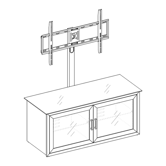
- Page 15 A s s e m b l y I n s t r u c t i o n s f o r F l o a t i n g S w i v e l M o u n t FLAT WASHER LOCK WASHER 2-1/4”...
- Page 16 Assembly Instructions for Floating Swivel Mount FLAT WASHER 5/8” BOLT LOCK WASHER (4 used in this step) (4 used in this step) (4 used in this step) ③ ⑦ ⑧ 26. Fasten the SWIVELING BRACKET (M) to the top of the SPINE (D) with four 5/8” BOLTS (3) and WASHERS (7 and 8).
- Page 17 Assembly Instructions for Floating Swivel Mount FLAT WASHER 1/2” BOLT LOCK WASHER (4 used in this step) (4 used in this step) (4 used in this step) ⑧ ⑦ ② 27. Hold and attach the flat side of the MOUNTING FRAME (N) onto the SWIVELING BRACKET (M) using four 1/2”...
- Page 18 Assembly Instructions for Floating Swivel Mount 5/8” BOLT (4 used in this step) ③ 28. Attach 2 CABLE WHEELS (P) onto the backside of the SPINE (D) with the 5/8” BOLTS (3). NOTE: You can use the CABLE WHEELS to help keep the entertainment center’s cables and cords organized.
- Page 19 Mounting the Monitor Brackets to a Television with a Flat Back NOTE: For televisions with a curved or recessed back, proceed directly to next page. 29. Determine the correct diameter of the bolt the TV requires by hand threading them into the threaded insert on the back of the TV.
- Page 20 Mounting the Monitor Brackets to a Television with a Curved/Recess Back 31. Determine the correct diameter of the bolt the TV requires by hand threading them into the threaded insert on the back of the TV. If you encounter any resistance, stop immediately. If you are unable to find the correct bolt consult a local hardware store.
- Page 21 Assembly Instructions for Floating Swivel Mount MAKE SURE ALL BOLTS ARE TIGHT AND THE SPINE IS AT A 90 DEGREE ANGLE. USE A QUALITY LEVEL TO VERIFY THE MOUNTING FRAME IS LEVEL PRIOR TO INSTALLATION OF TV. 33. Once the MONITOR BRACKETS (O) are attached onto the back of television, ask for assistance to lift the television up to attach the MONITOR BRACKETS onto the MOUNTING FRAME (N).
- Page 22 Assembly Instructions for Floating Swivel Mount Tools required: Hex wrench (provided), Phillips screwdriver, Mallet, Power Drill, and 3/8” Drill Bit. 35. Repeat steps 17 through 19 to install the TOP GLASS (K) and GLASS SHELVES (L) in place. 36. Carefully move the console and position it at the desired location against a wall. Now, follow the instructions printed on the plastic bag containing the TIPPING RESTRAINT HARDWARE KIT to mount the tipping restraint to the SPINE and the wall.
- Page 23 The following steps are only for those who wish to mount their TV directly to the wall. If you have already mounted your TV to the Swinging Floater or plan to display your TV on the top surface of the Console, disregard the following steps. Assembly Instructions for Universal Wall Mount Installing the Mounting Frame onto a WOODEN STUD WALL 2.50"...
- Page 24 Assembly Instruction for installing Mounting Frame onto a BRICK, SOLID CONCRETE OR CONCRETE BLOCK WALL 2.50" (63 mm) Maximum weight 135 lb. (61.2 kg) Concrete Anchors should only be used for masonry mounting. NEVER use the wall anchors to mount the unit to drywall. NOTE: If you are mounting your TV to a wall with wooden studs, skip this section.
- Page 25 Assembly Instructions 44. Attach the MONITOR BRACKETS (O) to the back of the television following steps 29 and 30, or 31 and 32, depending on the type of TV that you own. Once the MONITOR BRACKETS are attached onto the back of television, ask for assistance to lift the television up to attach the MONITOR BRACKETS onto the MOUNTING FRAME (N).
-
Page 26: Care And Maintenance
Should this product be defective in workmanship or materials or fail under normal use, we will repair or replace it for up to one (1) year from date of purchase. Every Whalen Furniture product is designed to meet your highest expectations. We guarantee that you will immediately see the value of our fine furniture. - Page 27 FECHA DE COMPRA Cabinete 3 en 1 para Televisión Modelo # XLCD-15 Patentes de E.U.A. 8,079,311 & 8,191,485 Este producto esta diseñado para configuración 3 en 1. Por favor escoga cual de las 3 opciones es adecuada para usted. Para fácil ensamble, nosotros le brindamos los Instructivos de ensamble para cada opción.
- Page 28 P E S O S M Á X I M O S R E C O M E N D A D O S FABRICANTE: Whalen Furniture Manufacturing CATALOGO: Cabinete 3 en 1 para Televisión (XLCD-15) HECHO EN CHINA PARA LA MAYORÍA DE LAS TELEVISIONES CON PANTALLA PLANA DE 55”...
- Page 29 Lista de Partes y Artículos de Ferretería Por favor lea completamente las instrucciones y verifique que estén todas las partes antes de iniciar el ensamble. A- REPISA SUPERIOR (1) B- REPISA METÁLICA INFERIOR (1) C- REPISA FRONTAL (1) D- POSTE (1) E- PANEL IZQUIERDO (1) F- PANEL DERECHO (1) G- PANEL DIVISOR (1)
- Page 30 Lista de Partes y Artículos de Ferretería Por favor lea completamente las instrucciones y verifique que estén todas las partes antes de iniciar el ensamble. (1) VENTOSA (6+1 extra) (2) TORNILLO DE 1/2” (4+1 extra) (3) TORNILLO DE 5/8” (14+1 extra) (4) TORNILLO DE 1”...
- Page 31 Juego de Montaje TORNILLO de 4x12 mm TORNILLO de 4x30 mm TORNILLO de 5x12 mm TORNILLO de 5x30 mm TORNILLO de 6x12 mm TORNILLO de 6x35 mm TORNILLO de 8x16 mm TORNILLO de 8x40 mm ARANDELA CANDADO ARANDELA CANDADO ARANDELA CANDADO ARANDELA CANDADO de 4 mm (4) de 5 mm (4)
-
Page 32: Instrucciones De Ensamblaje
Instrucciones de ensamblaje TORNILLO DE 1” (3 usados en este paso) ④ ARANDELA PLANA TORNILLO DE 1-1/4” ARANDELA PRESIÓN (4 usados en este paso) (4 usados en este paso) (4 usados en este paso) ⑤ ⑧ ⑦ Nota: Por favor no apriete completamente todos los TORNILLOs, hasta que termine con el ensamble de las partes, después asegure completamente todos los TORNILLOs, ésto lo hará... - Page 33 Instrucciones de ensamblaje ARANDELA PLANA TORNILLO DE 1” TORNILLO 5/8” ARANDELA PRESIÓN (4 usados en este paso) (4 usados en este paso) (4 usados en este paso) (4 usados en este paso) ③ ⑦ ④ ⑧ 4. Alinee los pernos de madera en el PANEL IZQUIERDO (E) con los agujeros previamente perforados de la REPISA FRONTAL (C) y apriételas.
- Page 34 Instrucciones de ensamblaje TORNILLO DE 2” (2 usados en este paso) ⑨ 7. Usar los pernos de madera como guía, alinear y conectar el PANEL DIVISOR (G) en el PANEL INFERIOR (H) utilizando dos TORNILLOS de 2" (9). Apriete los tornillos con un destornillador estrella.
- Page 35 Instrucciones de ensamblaje ARANDELA PLANA TORNILLO 5/8” TORNILLO DE 1/2” ARANDELA PRESIÓN (2 usados en este paso) (2 usados en este paso) (6 usados en este paso) (2 usados en este paso) ③ ⑩ ⑦ ⑧ 8. Alinee y coloque el último ensamble a la estructura montada. Inserte y atornille dos TORNILLOS de 5/8"...
- Page 36 Instructivo de ensamblaje TORNILLO DE 1/2” (10 usados en este paso) ⑩ 10. Ahora, vuelva a apretar todos los tornillos. Asegúrese de que todas las piezas estén apretadas y que no haya espacios entre las partes. Esto ayudará a mantener el cuadrado unitario. 11.
- Page 37 Instrucciones de ensamblaje JALADERA C/TORNILLOS (2 usados en este paso) ⑯ 12. Poner la unidad en pie. 13. Extienda los brazos de las bisagras pre-unidos en un PANEL DE PUERTA (J) y unir a las bases de bisagras en el PANEL DERECHO (F). Alinee e inserte la "U" en la ranura de la bisagra del brazo bajo la cabeza del tornillo en la base de la bisagra.
- Page 38 Instrucciones de ensamblaje para ensamble tipo Mesa VENTOSA SOPORTE REPISA (6 usados en este paso) (8 usados en este paso) ⑪ ① 17. Poner las VENTOSAS (1) en los agujeros superiores de la REPISA SUPERIOR (A). Consejo: Si una ventosa resiste a la inserción, trate de presionar en el centro de la misma con la llave Hexagonal mientras gira hacia la derecha en el agujero.
- Page 39 Instrucciones de ensamblaje para ensamble tipo Mesa TOPE ACRILÍCO (1 usado en este paso) ⑮ NOTA: Debe instalar el TOPE para TV, con ello puede prevenir que esta caiga cuando usted coloque su TV directamente sobre la repisa superior de la consola. 20.
- Page 40 Instrucciones de ensamblaje para ensamble tipo Mesa Herramienta requerida: Llave hexagonal (proporcionada), Desarmador de Cruz, Mazo, Taladro, Broca de 3/8 de pulgadas (9,5 mm). 23. Coloque la Consola en la parte del cuatro que desea cerca de una pared. A continuación siga las instrucciones que se encuentran en la bolsa de plástico con el Juego Sujetador hacia el POSTE.
- Page 41 I n s t r u c c i o n e s d e E n s a m b l e p a r a : M o n t a j e f l o t a n t e g i r a t o r i o ARANDELA PLANA Tornillo de 2-1/4”...
- Page 42 Instructivo de Ensamble para opción: Montaje flotante giratorio ARANDELA PLANA TORNILLO 5/8” ARANDELA PRESIÓN (4 usados en este paso) (4 usados en este paso) (4 usados en este paso) ③ ⑦ ⑧ 26. Fije el SOPORTE GIRATORIO (M) en la parte superior del POSTE (D) con cuatro TORNILLOS de 5/8"...
- Page 43 Instructivo de Ensamble para opción: Montaje flotante giratorio ARANDELA PLANA ARANDELA PRESIÓN TORNILLO DE 1/2” (4 usados en este paso) (4 usados en este paso) (4 usados en este paso) ⑧ ⑦ ② 27. Mantenga y coloque el lado plano del MARCO D EMONTAJE (N) en el SOPORTE GIRATORIO (M) con cuatro TORNILLOS de 1/2"...
- Page 44 Instructivo de Ensamble para opción: Montaje flotante giratorio TORNILLO DE 5/8” (4 usados en este paso) ③ 28. Asegure 2 GUÍAS PARA CABLE (P) en la parte posterior del POSTE (D) con TORNILLOS de 5/8” (3). NOTA: Puede utilizar las GUÍAS PARA CABLE para ayudar a mantener los cables del centro del entretenimiento organizados.
- Page 45 Para montar el Marco en Televisiones con Respaldo Plano NOTA: Para Televisiones con Respaldos Curvos o desnivel Proceda directamente al página siguiente. 29. Determine el diámetro correcto de tornillos que utilizará en su televisión atornillando con sus manos para asegurar que entren bien, si encuentra resistencia detenganse inmediatamente. Si no encuentra el tornillo adecuado dirígase a su tienda de ferretera local para el mismo.
- Page 46 Para montar el Marco en Televisiones con Respaldo curvo / desnivel 31. Determine el diámetro correcto de tornillos que utilizará en su televisión atornillando con sus manos para asegurar que entren bien, si encuentra resistencia detenganse inmediatamente. Si no encuentra el tornillo adecuado dirígase a su tienda de ferretera local para el mismo. 32.
- Page 47 Instrucciones de ensamblaje para opción: Montaje flotante giratorio CERCIÓRESE QUE TODOS LOS TORNILLOS ESTÉN APRETADOS Y EL POSTE ESTÉ A 90 GRADOS Y USANDO DE CALIDAD NIVEL, VERIFIQUE QUE EL MARCO ESTE NIVELADO ANTES DE HACER LOS BARRENOS ANTES DE INSTALAR LA TELEVISIÓN. 33.
- Page 48 Instrucciones de ensamblaje para opción: Montaje flotante giratorio Herramienta requerida: Llave hexagonal (proveida), Desarmador de Cruz, Mazo, Taladro, Broca de 3/8” (9,5 mm) Repita los pasos 17 a 19 para instalar el VIDRIO SUPERIOR (K) y REPISA DE VIDRIO (L) en lugar.
- Page 49 Los pasos siguientes son solo para en caso de querer montar su TV en la pared. Si ya monto su TV en el Marco Giratorio o planea poner su TV directamente sobre la consola, no tomar en cuenta los pasos siguientes. Instrucciones de ensamblaje para Marco de Montaje Universal Instalando el Marco a una pared de Madera 2.50"...
-
Page 50: Instrucciones De Ensamblaje
Instrucciones de ensamblaje de Marco de Montaje para Ladrillo, Concreto o Bloque de Concreto 2.50" (63 mm) Máxima carga 135 Libras (61,2 kg) Taquetes para concreto deben ser utilizadas unicamente para concreto NUNCA en tabla roca. NOTA : Si esta montando esta TV a una pared con barrotes de madera, no continue en esta sección. - Page 51 Instrucciones de ensamblaje 44. Fije los SOPORTE DE MONITOR (O) a la parte trasera del televisor siguiendo los pasos 29 y 30, o 31 y 32, dependiendo del tipo de TV que usted posee. Una vez que los soportes de monitor se unen en la parte posterior de la televisión, pedir ayuda para levantar la televisión hasta adjuntar los soportes de monitor en el MARCO DE MONTAJE (N).
-
Page 52: Mantenimiento Y Cuidados
Nosotros lo repararemos o lo re-emplazaremos hasta por un año a partir de la fecha de compra. Todo producto de Whalen Furniture es diseñado para alcanzar sus espectativas más altas. Nosotros le garantizamos que inmediatamente podrá ver el valor de nuestra mercancia de la más alta calidad.
Need help?
Do you have a question about the XLCD-15 and is the answer not in the manual?
Questions and answers