Table of Contents
Advertisement
Quick Links
Instructions and Parts List
3M-Matic
700r-s
Stainless Steel
Random
Case Sealer
with
AccuGlide SST
Taping Heads
Serial No.
For reference, record machine serial number here.
3M Industrial Adhesives and Tapes
3M Center, Building 220-5E-06
St. Paul, MN 55144-1000
™
Type 10500
™
Important Safety
Information
BEFORE INSTALLING OR
OPERATING THIS
EQUIPMENT
Read, understand, and follow
all safety and operating
instructions.
Spare Parts
It is recommended you
immediately order the spare
parts listed in the "Spare
Parts/Service Information"
section. These parts are
expected to wear through
normal use, and should be
kept on hand to minimize
production delays.
"3M-Matic"and "AccuGlide" are Trademarks
of 3M, St. Paul, MN 55144-1000
Printed in U.S.A.
© 3M 2005 44-0009-2039-5 (A)
Advertisement
Table of Contents
Troubleshooting

Subscribe to Our Youtube Channel
Related Manuals for 3M Matic 700r-s


Summary of Contents for 3M Matic 700r-s
- Page 1 Serial No. For reference, record machine serial number here. "3M-Matic"and "AccuGlide" are Trademarks 3M Industrial Adhesives and Tapes of 3M, St. Paul, MN 55144-1000 3M Center, Building 220-5E-06 Printed in U.S.A. St. Paul, MN 55144-1000 © 3M 2005 44-0009-2039-5 (A)
- Page 2 THIS PAGE INTENTIONALLY LEFT BLANK...
- Page 3 THIS PAGE INTENTIONALLY LEFT BLANK...
- Page 4 Minimum billing on parts orders will be $25.00. Replacement part prices available on request. $10.00 restocking charge per invoice on returned parts. Note : Outside the U.S., contact the local 3M subsidiary for parts ordering information. "3M-Matic", "AccuGlide" and “Scotch” are trademarks 3M Industrial Adhesives and Tapes of 3M, St.
- Page 5 THIS PAGE INTENTIONALLY LEFT BLANK...
- Page 6 Order parts by part number, part description and quantity required. Also, when ordering parts and/or additional manuals, include machine name, number and type. "3M-Matic", "AccuGlide" and “Scotch” are trademarks 3M Industrial Adhesives and Tapes of 3M, St. Paul, Minnesota 55144-1000 3M Center, Building 220-5E-06 Printed in U.S.A.
- Page 7 THIS PAGE INTENTIONALLY LEFT BLANK...
-
Page 8: Table Of Contents
Instruction Manual 700r-s Stainless Steel, Random Case Sealer, Type 10500 This instruction manual is divided into two sections as follows: Section Includes all information related to installation, operation and parts for the case sealer. Section Includes specific information regarding the AccuGlide™ SST 2 Inch Taping Heads. Table of Contents Page Section... - Page 9 Table of Contents (Continued) Page Maintenance ............................ 22 - 24 Cleaning ......................Lubrication ......................Box Drive Belt Replacement ................Circuit Breaker ....................Knife Replacement, Taping Head ............... Adjustments ........................... 25 - 27 Box Drive Belt Tension ..................25 - 27 Taping Head Adjustments ..................
-
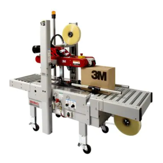
Page 10: Intended Use
Intended Use The 3M-Matic 700r-s Stainless Steel Random Case Sealer with AccuGlide SST Taping Heads is designed to apply a “C” clip of Scotch ® pressure-sensitive film box sealing tape to the top and bottom center seam of regular slotted containers. The 700r-s automatically adjusts to a wide range of box sizes (see "Specifications Section –... -
Page 11: Equipment Warranty And Limited Remedy
3M is notified of the problem no later than five (5) calendar days after the warranty period. If 3M is unable to repair or replace the part within a reasonable time, then 3M at its option, will replace the equipment or refund the purchase price. -
Page 12: Important Safeguards
Important Safeguards This safety alert symbol identifies WARNING (continued) important messages in this manual. READ AND UNDERSTAND THEM BEFORE • To reduce the risk associated with impact INSTALLING OR OPERATING THIS hazards: EQUIPMENT. − Always use appropriate supporting means when working under the upper drive Explanation of Signal Word Consequences assembly •... - Page 13 Important – In the event the following safety labels are damaged or destroyed, they must be replaced to ensure operator safety. Replacement part numbers for individual labels are shown in Figures 1-1 through 1-3, or a label kit, part number 78-8098-9177-9, is available that includes all labels used on the machine. Figure 1-1 – Replacement Labels/3M Part Numbers...
- Page 14 Important Safeguards (Continued) Figure 1-2 – Replacement Labels/3M Part Numbers...
- Page 15 Important Safeguards (Continued) Figure 1-3 – Replacement Labels/3M Part Numbers...
- Page 16 Important Safeguards (Continued) Skill 2 - Mechanical Maintenance Technician WARNING This operator is trained to use the machine as the MACHINE OPERATOR and in addition is able to work with the safety protection disconnected, to • To reduce the risk associated with check and adjust mechanical parts, to carry out mechanical and electrical hazards: maintenance operations and repair the machine.
-
Page 17: Specifications
A pressure regulator is included The machine is equipped with two 1/6 HP gearmotors and comes with an 2.4 m [eight foot] standard neoprene covered power cord and a grounded plug. Contact your 3M Representative for power requirements not listed above. - Page 18 ** 200 mm [8.0 inch] minimum to 725 mm [28.5 inch] maximum height with columns adjusted to upper position. (See "Special Set-Up Procedure".) Special modifications may be available for carton sizes not listed above. Contact your 3M Representative for information. Note: The case sealer can accommodate most boxes within the size range listed above. However, if the box length (in direction of seal) to box height ratio is .5 or less, then several boxes should be test run...
-
Page 19: Specifications
Specifications (Continued) 10. Machine Dimensions: Minimum 1180 1575 610*** 1640 [Inches] [31] [40 .5] [62] [18] [24] [4.75] [24.5] [64.5] Maximum 2185*** [Inches] [86] [35] * Exit conveyor is optional ** Casters are optional *** When columns are adjusted to upper position, "B" minimum dimension is 570 mm [22.5 inch] and "H"... -
Page 20: Installation And Set-Up
If damage is evident, file a damage claim immediately with the transportation company The case sealer requires a 5 bar gauge pressure and also notify your 3M Representative. 110 litre/min [70 PSIG], @21°C, 1.01 bar [3.75 SCFM] compressed air supply. As shown in... - Page 21 Installation and Set-Up (Continued) Figure 2-1 – 700r-s Frame Set-Up 10. Check for free action of both upper and lower taping heads. 9. Cut and remove cable ties on both upper and lower taping heads. (Applying/buffing rollers are held retracted for shipment.) WARNING WARNING •...
-
Page 22: Infeed Conveyor Assembly
Installation and Set-Up (Continued) 13. Use appropriate material handling equipment to remove the machine from the pallet and move it into position. Whenever the machine is lifted with a fork truck, insure that the forks span completely across the machine frame and do not contact any wiring or mechanism under the machine frame. -
Page 23: Machine Bed Height
Installation and Set-Up (Continued) MACHINE BED HEIGHT 1. Use appropriate material handling equipment Adjust machine bed height. The case sealer is and blocking techniques to raise the equipped with four adjustable legs that are machine frame to allow adequate leg located at the corners of the machine frame. -
Page 24: Bumper Supports
Installation and Set-Up (Continued) BUMPER SUPPORTS (Upper Drive Assembly) ELECTRICAL CONNECTION AND CONTROLS The electrical control box and "On/Off" switch WARNING are located on the lower left side of the machine frame. See Figure 3-1. If desired, for operator • To reduce the risk associated with impact convenience, the "On/Off"... -
Page 25: Operation
Operation WARNING • To reduce the risk associated with mechanical and electrical hazards: − Read, understand and follow all safety and operating instructions before operating or servicing the case sealer Refer to Figure 3-1 and 3-2 below to acquaint yourself with the various components and controls of the case sealer. -
Page 26: Machine Switches And Controls
Operation (Continued) Figure 3-2 – Controls, Valves and Switches Always turn the air "Off" when machine is not in Electrical "On/Off" Switch use, when servicing the machine, or when The box drive belts are turned on and off ("Off" connecting or disconnecting air supply line. button is red) with the electrical switch on the side of the machine frame. - Page 27 Operation (Continued) Pressure Regulator regulates main air pressure to the machine to adjust pressure, pull knob up and turn – push down to lock setting. Filter removes dirt and moisture from plant air before it enters the case sealer pneumatic circuits.
-
Page 28: Operating "Warnings
Operation (Continued) For boxes which are fully packed with products that support the top flaps, the adjustment of this regulator is not critical since the boxes can support the pressure of the upper frame (drive belts) at a wide range of regulator settings. However, if under-filled or fragile boxes are sealed, this regulator can be used to set the upper frame pressure to a minimum that is still... -
Page 29: Tape Loading/Threading
Operation (Continued) Important – Before turning drive belts on, be sure no tools or other objects are on the conveyor bed. Tape Loading/Threading See Section II. Note – If lower tape drum is mounted in alternate lower outboard position, remove taping head from machine bed by pulling straight up, insert threading needle in taping head and replace taping head. -
Page 30: Box Sealing
Operation (Continued) CAUTION • To reduce the risk associated with pinch and entanglement hazards: − Keep hands, hair, loose clothing, and jewelry away from moving belts and taping heads 3. Once the box is pushed under the upper taping head, the upper drive assembly raising switch is released causing the upper drive assembly to descend onto the box top, as shown in Figure 3-9, allowing the drive belts to convey... -
Page 31: Maintenance
Maintenance The case sealer has been designed for long, trouble Lubrication free service. The machine will perform best when it receives routine maintenance and cleaning. Most of the machine bearings, including the drive Machine components that fail or wear excessively motor, are permanently lubricated and sealed and do should be promptly repaired or replaced to prevent not require additional lubricant. -
Page 32: Box Drive Belt Replacement
To reduce the risk associated with impact hazards: − Always use appropriate supporting means when working under the upper drive assembly Box Drive Belt Replacement Note – 3M recommends the replacement of drive belts in pairs, especially if belts are unevenly worn. LOWER DRIVE BELTS Figure 4-2 1. -
Page 33: Circuit Breaker
Maintenance (Continued) WARNING • To reduce the risk associated with mechanical and electrical hazards: − Turn electrical and air supply off and disconnect before performing any adjustments, maintenance or servicing the machine or taping heads Circuit Breaker Knife Replacement, Taping Head See Section II, "Maintenance –... -
Page 34: Adjustments
Adjustments WARNING • To reduce the risk associated with mechanical and electrical hazards: − Turn electrical and air supply off and disconnect before performing any adjustments, maintenance or servicing the machine or taping heads Box Drive Belt Tension The four continuously moving drive belts convey boxes through the tape applying mechanism. The box drive belts are powered by electric motors. - Page 35 Adjustments (Continued) WARNING • To reduce the risk associated with mechanical and electrical hazards: − Turn electrical and air supply off and disconnect before performing any adjustments, maintenance or servicing the machine or taping heads Refer to Figure 5-2 and 5-3 and adjust belt tension as follows: 1.
-
Page 36: Taping Head Adjustments
Adjustments (Continued) WARNING • To reduce the risk associated with mechanical and electrical hazards: − Turn electrical and air supply off and disconnect before performing any adjustments, maintenance or servicing the machine or taping heads Figure 5-3 – Box Drive Belt Tension Adjustment, Upper Belts (Infeed End) Taping Head Adjustments –... -
Page 37: Special Set-Up Procedure
Special Set-Up Procedure WARNING • To reduce the risk associated with mechanical and electrical hazards: − Turn electrical and air supply off and disconnect before performing any adjustments, maintenance or servicing the machine or taping heads Figure 6-1 – Case Sealer Frame Changes... - Page 38 Special Set-Up Procedure (Continued) WARNING • To reduce the risk associated with mechanical and electrical hazards: − Turn electrical and air supply off and disconnect before performing any adjustments, maintenance or servicing the machine or taping heads TAPING HEAD WARNING •...
-
Page 39: Box And Machine Bed Height Range
Special Set-Up Procedure (Continued) WARNING • To reduce the risk associated with mechanical and electrical hazards: − Turn electrical and air supply off and disconnect before performing any adjustments, maintenance or servicing the machine or taping heads Box and Machine Bed Height Range – Refer to Figure 6-4 Moving the outer columns up one set of mounting holes increases the maximum box size handled by the 700r-s case sealer and decreases the minimum machine bed height. -
Page 40: Box Height Range
Special Set-Up Procedure (Continued) WARNING • To reduce the risk associated with mechanical and electrical hazards: − Turn electrical and air supply off and disconnect before performing any adjustments, maintenance or servicing the machine or taping heads Box Height Range – (Refer to Figure 6-5) The operating range of the upper drive assembly can be adjusted to minimize its movement to the range of box heights being sealed. -
Page 41: Troubleshooting
Troubleshooting The Troubleshooting Guide lists some possible machine problems, causes and corrections. Also see Section II "Troubleshooting" for taping head problems. Troubleshooting Guide Problem Correction Cause Drive belts do not convey boxes Check machine specifications. Narrow boxes Boxes are narrower than recommended, causing slippage and premature belt wear. -
Page 42: Troubleshooting
Troubleshooting (Continued) Troubleshooting Guide Problem Cause Correction Upper drive assembly does not Lower air pressure Disconnect the air supply. Make move up or moves up slowly sure main pressure regulator reads zero. Reconnect air supply and adjust regulator to read 70 PSIG [5 bar]. -
Page 43: Electrical Diagram
Electrical Diagram WARNING • To reduce the risk associated with mechanical and electrical hazards: − Turn electrical and air supply off and disconnect before performing any adjustments, maintenance or servicing the machine or taping heads Figure 7-1 – Electrical Diagram... -
Page 44: Pneumatic Diagram
Pneumatic Diagram WARNING • To reduce the risk associated with mechanical and electrical hazards: − Turn electrical and air supply off and disconnect before performing any adjustments, maintenance or servicing the machine or taping heads Figure 8-1 – Pneumatic Diagram... -
Page 45: Replacement Parts And Service Information
Replacement Parts And Service Information Spare Parts It is suggested that the following spare parts be ordered and kept on hand: Qty. Ref. No. Part Number Description 10438-70 & 10439-84 78-8070-1531-4 Belt - Drive W/Pin Also see Section II for recommended taping head spare parts. Label Kit In the event that any labels are damaged or destroyed, they must be replaced to ensure operator safety. -
Page 46: Options/Accessories
Options/Accessories For additional information on the options/accessories listed below, contact your 3M Representative. Part Number Option/Accessory 70-0064-0379-7 Caster Kit Attachment 70-0064-0378-9 Conveyor Extension Attachment (exit only) 78-8060-8156-4 AccuGlide SST 2 Inch Upper Taping Head, Type 18900 78-8060-8157-2 AccuGlide SST 2 Inch Lower Taping Head, Type 18900... -
Page 47: Replacement Parts Illustrations And Parts Lists
Refer to the first page of this instruction manual “Replacement Parts and Service Information” for replacement parts ordering information. IMPORTANT – Not all the parts listed are normally stocked items. Some parts or assemblies shown are available only on special order. Contact 3M/Tape Dispenser Parts to confirm item availability. - Page 48 THIS PAGE SHOULD NOT BE THIS PAGE IS BLANK HERE, NEEDS TO BE DELETED.
- Page 49 700r-s Stainless Steel Random Case Sealer Frame Assemblies...
- Page 50 700r-s Stainless Steel Random Case Sealer Figure 10425...
- Page 51 Figure 10425 Ref. No. 3M Part No. Description 10425-1 78-8134-1933-6 Tape Roll Bracket Assy 10425-2 78-8134-1934-4 Tape Drum Bracket Assy 10425-3 78-8134-1935-1 Bracket - Tape Drum, Upper 10425-4 78-8134-1936-9 Bracket - Tape Drum, Lower 10425-5 78-8070-1568-6 Cap - Bracket 10425-6...
- Page 52 700r-s Stainless Steel Random Case Sealer Figure 10433...
- Page 53 Figure 10433 Ref. No. 3M Part No. Description 10433-1 78-8134-2006-0 Conveyor Bed Assembly 10433-2 78-8134-2007-8 Bed – Conveyor 10433-3 78-8134-1991-4 Support – Drive 10433-4 78-8060-8319-8 Screw – Hex Hd, M8 x 20 10433-5 78-8060-8308-1 Washer – Plain, 8 mm 10433-6 78-8134-1992-2 Leg Assembly –...
- Page 54 700r-s Stainless Steel Random Case Sealer Figure 10434...
- Page 55 Figure 10434 Ref. No. 3M Part No. Description 10434-1 78-8134-2015-1 Cylinder - Air, C65D32-580C-Y02 10434-2 78-8094-6457-7 Cap 1/8" 10434-3 78-8091-0313-4 Elbow 10434-4 78-8076-4680-3 Screw - Cushioning 10434-5 78-8060-8091-3 Valve - R/0-3-pk-3 10434-6 78-8076-4664-7 Union - Female 10434-7 78-8076-4665-4 Indicator - Visual...
- Page 56 700r-s Stainless Steel Random Case Sealer Figure 10430...
- Page 57 Figure 10430 Ref. No. 3M Part No. Description 10430-1 78-8134-2001-1 Support - Electric Box 10430-2 78-8113-6759-4 Electric Box 10430-3 78-8094-6381-9 Screw - Soc.Hd, M4x15 10430-4 78-8060-8297-6 Washer - Flat, M4 10430-5 78-8060-8321-4 Nut - Self Locking, M4 10430-6 78-8076-4715-7 Cord Grip ST13,5...
- Page 58 700r-s Stainless Steel Random Case Sealer Figure 10438/1 of 2...
- Page 59 Figure 10438 (Page 1 of 2) Ref. No. 3M Part No. Description 10438-1 78-8134-2080-5 Drive Assy - Bottom, W/O Motor 10438-2 78-8134-1970-8 Frame - Bottom Drive 78-8134-1947-6 10438-3 788134-1947-6 Spacer 10438-4 78-8060-8292-7 Screw - Hex.Hd, M6x12 10438-5 78-8134-1954-2 Belt Tensioning Assy - R/H...
- Page 60 700r-s Stainless Steel Random Case Sealer Figure 10438/2 of 2...
- Page 61 Figure 10438 (Page 2 of 2) Ref. No. 3M Part No. Description 10438-55 78-8060-8316-4 Key 6x6x20 10438-56 78-8060-8313-1 Key 5x5x30 10438-57 78-8060-8278-6 Bushing 10438-58 78-8060-8374-3 Flange - Shaft 10438-59 78-8060-8352-9 Shaft - Drive 10438-60 78-8060-8345-3 Chain - 3/8", 57 pitch...
- Page 62 700r-s Stainless Steel Random Case Sealer Figure 10435...
- Page 63 Figure 10435 Ref. No. 3M Part No. Description 10435-1 78-8134-2016-9 Column - Outer 10435-2 78-8134-2017-7 Pin - Cylinder 10435-3 78-8100-0791-0 E-Ring 10435-4 78-8054-8821-6 Cap /19 10435-5 78-8060-8307-3 Screw - Soc.Hd, M8x20 10435-6 78-8060-8308-1 Washer - Flat, M8 10435-7 78-8134-2018-5 Plate - Bumper Support...
- Page 64 700r-s Stainless Steel Random Case Sealer Figure 10439/1 of 2...
- Page 65 Figure 10439 (Page 1 of 2) Ref. No. 3M Part No. Description 10439-1 78-8134-2092-0 Drive Assy - Top, W/O Motor 10439-2 78-8134-2093-8 Frame - Top Drive 10439-3 78-8134-1944-3 Guide - Drive Belt 10439-4 78-8060-8333-9 Screw - Flat Hd, M5x20 10439-5...
- Page 66 700r-s Stainless Steel Random Case Sealer Figure 10439/2 of 2...
- Page 67 Figure 10439 (Page 2 of 2) Ref. No. 3M Part No. Description 10439-55 78-8060-8280-2 Shaft - Pulley 10439-56 78-8060-8320-6 Nut - Self Locking M8 10439-57 78-8057-5808-9 Belt - Timing, 187L100 10439-58 78-8057-5724-8 Belt - Timing, 187L050 10439-59 78-8060-8283-6 Pulley - Timing, 11 teeth...
- Page 68 700r-s Stainless Steel Random Case Sealer Figure 10431...
- Page 69 Figure 10431 Ref. No. 3M Part No. Description 10431-1 78-8134-1928-6 Housing - Wire 10431-2 78-8076-4702-5 Grommet /28 10431-3 78-8060-8332-1 Screw - Soc.Hd, M8x16 10431-4 78-8134-1929-4 Strap - Wire 10431-5 78-8060-8300-8 Screw - Hex.Hd, M5x10 10431-6 78-8060-8303-2 Washer - Flat, M5...
- Page 70 700r-s Stainless Steel Random Case Sealer Figure 10436...
- Page 71 Figure 10436 Ref. No. 3M Part No. Description 10436-1 78-8134-2034-2 Infeed Conveyor Assy 10436-2 78-8134-2035-9 Frame - Infeed 10436-3 78-8134-2036-7 Frame 10436-4 788134-2037-5 Spacer - Bearing 10436-5 78-8134-2038-3 Bearing - 6005-2RS 10436-6 78-8134-2039-1 Pivot - Infeed 10436-7 78-8134-2040-9 Key 7x8x25...
- Page 72 700r-s Stainless Steel Random Case Sealer Figure 10437...
- Page 73 Figure 10437 Ref. No. 3M Part No. Description 10437-1 78-8134-2074-8 Infeed Conveyor Assy 10437-2 78-8134-2075-5 Plate - Reinforcement 10437-3 78-8134-2076-3 Plate - Reinforcement 10437-4 78-8134-2009-4 Screw - Special, M5x16 10437-5 78-8134-2077-1 Roller /32x492 10437-6 78-8134-2078-9 Plate - Roller 10437-7 78-8100-0905-6 Screw - Hex.Hd, M4x10...
- Page 74 THIS PAGE INTENTIONALLY LEFT BLANK...
Need help?
Do you have a question about the Matic 700r-s and is the answer not in the manual?
Questions and answers