Table of Contents
Advertisement
Quick Links
Instructions and Parts List
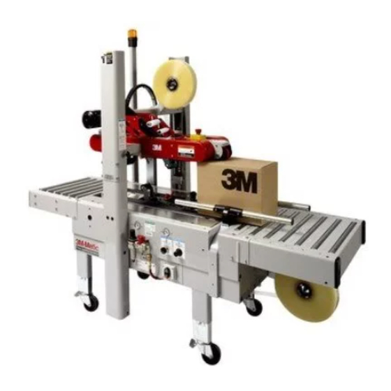
3M-Matic
700a3
Adjustable
Case Sealer
with
AccuGlide 2+
Taping Heads
Serial No.
For reference, record machine serial number here.
3M Industrial Adhesives and Tapes
3M Center, Building 220-5E-06
St. Paul, MN 55144-1000
™
Type 39600
™
Important Safety
Information
BEFORE INSTALLING
OR OPERATING THIS
EQUIPMENT
Read, understand, and
follow all safety and
operating instructions.
Spare Parts
It is recommended you
immediately order the
spare parts listed in the
"Spare Parts/Service
Information" section.
These parts are expected
to wear through normal
use, and should be kept
on hand to minimize
production delays.
"3M-Matic"and "AccuGlide" are Trademarks of,
3M St. Paul, MN 55144-1000
Printed in U.S.A.
© 3M 2011 44-0009-2057-7 (C070111-NA)
Advertisement
Chapters
Table of Contents
Troubleshooting

Subscribe to Our Youtube Channel
Related Manuals for 3M Matic 700a3


Summary of Contents for 3M Matic 700a3
- Page 1 Serial No. For reference, record machine serial number here. "3M-Matic"and "AccuGlide" are Trademarks of, 3M Industrial Adhesives and Tapes 3M St. Paul, MN 55144-1000 3M Center, Building 220-5E-06 Printed in U.S.A.
- Page 2 This instruction manual covers safety aspects, handling and transport, storage, unpacking, preparation, installation, operation, adjustments, maintenance, troubleshooting, repair work and servicing plus parts list of the 3M-Matic 700a3 Adjustable case sealer. 3M Industrial Adhesives and Tapes 3M Center, Building 220-5E-06 St.
-
Page 3: Replacement Parts And Service Information
Minimum billing on parts orders will be $25.00. Replacement part prices available on request. $10.00 restocking charge per invoice on returned parts 3M-Matic , AccuGlide and Scotch 3M Industrial Adhesives and Tapes ™ ™ ™ Trademarks of 3M Center, Building 220-5E-06 3M St. - Page 4 THIS PAGE IS BLANK...
- Page 5 Order parts by part number, part description, and quantity required. Also, when ordering parts or additional manuals, include model/machine name, machine type, and serial number that are located on the identifi cation plate. 3M Industrial Adhesives and Tapes 3M-Matic , AccuGlide and Scotch ™...
- Page 6 THIS PAGE IS BLANK...
-
Page 7: Table Of Contents
TABLE OF CONTENTS - MANUAL 1: 700a3 Adjustable Case Sealer (For Taping Head Information - See MANUAL 2: AccuGlide™ 2+ Taping Heads - 3 inch) 700a3 Adjustable Case Sealer Page Cover Page Replacement Parts and Service Information ................ i - ii Table of Contents ......................... - Page 8 THIS PAGE IS BLANK...
- Page 9 TABLE OF CONTENTS (continued) 5. Shipment, Handling, and Storage 5.1 Packed Machine Shipment and Handling ................15 5.2 Overseas Shipment Packaging (Optional) ................15 5.3 Handling and Transportation of Uncrated Machine ............. 15 5.4 Machine Storage ......................... 15 6. Unpacking 6.1 Uncrating ..........................
- Page 10 THIS PAGE IS BLANK 10 iv...
- Page 11 TABLE OF CONTENTS (continued) 12. Operation 12.1 Operator’s Correct Working Position ................25 12.2 Starting the Machine ......................25 12.3 Starting Production ......................25 12.4 Tape Replacement ......................25 12.5 Box Size Adjustment ......................25 12.6 Cleaning ........................... 25 12.7 Table of Adjustments ......................25 12.8 Safety Devices Inspection ....................
- Page 12 ABBREVIATIONS AND ACRONYMS LIST OF ABBREVIATIONS, ACRONYMS 3M-Matic - Trademark of 3M St. Paul, MN 55144- 1000 AccuGlide - Trademark of 3M St. Paul, MN 55144-1000 Scotch - Trademark of 3M St. Paul, MN 55144-1000 Drw. - drawing - for example Fig.
-
Page 13: Introduction
1-INTRODUCTION 1.1 Manufacturing Specifications / Description / Intended Use The 3M-Matic 700a3 Adjustable Case Sealer with AccuGlide 2+ Taping Heads is designed to apply a “C” clip of Scotch ® pressure-sensitive fi lm box sealing tape to the top and bottom center seam of regular slotted containers. -
Page 14: How To Read And Use The Manual
3M-Matic 700a3 Adjustable case sealer 3M Indus- - Spare parts (last section) trial Adhesives and Tapes Division 3M Center, Bldg. 220-5E-06 St. Paul, MN 55144-1000 (USA) Edition All pages and diagrams are numbered. The spare July 2011 Copyright 3M 2011 All rights reserved. -
Page 15: General Information
2-GENERAL INFORMATION 2.1 Data Identifying Manufacturer and Machine For Commercial Use Only 2.2 Data for Technical Assistance and Service 2011 July 700a3-NA... -
Page 16: Warranty / Contents
3M’s factory or an authorized service station designated by 3M. A part will be presumed to have become defective after its warranty period unless the part is received or 3M is notifi ed of the problem no later than fi... -
Page 17: Safety
3-SAFETY 3.2 Explanation of Signal Word and 3.1 General Safety Information Possible Consequences Read all the instructions carefully before starting work with the machine; please pay particular atten- tion to sections marked by the symbol: This safety alert symbol identif es important messages in this manual. -
Page 18: Table Of Warnings
3-SAFETY (continued) 3.3 Table of Warnings WARNING • To reduce the risk associated with mechanical and electrical hazards: − Read, understand, and follow all safety and operating instructions before operating or servicing the case sealer. Figure 3-2 − Allow only properly trained and qualifi ed personnel to operate and service this equipment. - Page 19 3-SAFETY (continued) WARNING • To reduce the risk associated with sharp blade hazards: − Keep hands and fi ngers away from WARNING tape cutoff blades under orange blade Sharp Blade guards. The blades are extremely sharp. Important! Tape cutting blade. Never remove the safety device which covers the blade on the top and bottom taping units.
-
Page 20: Operator's Qualifi Cations Defi Nition
3-SAFETY (continued) 3.4 Operator's Qualifications WARNING - Machine Operator • - Mechanical Maintenance Technician To reduce the risk associated with - Electrical Maintenance Technician mechanical and electrical hazards: - Manufacturer’s Technician/Specialist − Read, understand, and follow all safety (See Section 3) and operating instructions before operating or servicing the case sealer. -
Page 21: Operator's Required Skill Levels
3-SAFETY (continued) Skill 2a: Electrical Maintenance Technician 3.11 Operator's Skill Levels Required to Perform This operator is trained to use the machine as the the Main Operations on the Machine MACHINE OPERATOR and in addition is able to: • Work with the safety protection disconnected The Table shows the minimum operator's skill for •... -
Page 22: Component Locations
3-SAFETY (continued) 3.12 Component Locations Refer to Figure 3-9 below to acquaint yourself with the various components and controls of the case sealer. Also refer to Manual 2 for taping head components. Upper Taping Head Height Adjustment Emergency Handle Stop Switch Upper Head... -
Page 23: Table Of Warnings And Replacement Labels
3.13 Table of Warnings and Replacements Labels (continued) 78-8095-1141-9 DOWN STOP 78-8095-1628-8 78-8113-8912-9 78-8070-1318-6 78-8070-1336-8 78-8070-1366-5 78-8113-6717-2 78-8062-4266-1 78-8137-0886-0 78-8060-8481-6 Leg Height Adjustment Label (not shown) 78-8070-1329-3 78-8070-1339-2 3M Logo (not shown) Figure 3-10 - Replacement Labels / 3M Part Numbers 2011 July 700a3-NA... -
Page 24: Power Requirements
The machine is equipped with two 1/6 HP gearmotors and comes with an 2.4 m [8 foot] standard neoprene covered power cord and a grounded plug. Contact your 3M Representative for power requirements not listed above. Contact your 3M Representative for power requirements not listed above. -
Page 25: Tape Roll Diameter
4-SPECIFICATIONS (continued) Specifications 6. Tape Roll Diameter Up to 405mm [16 inch] maximum on a 76.2mm [3 inch] diameter core. (Accommodates all system roll lengths of Scotch ® fi lm tapes.) 7. Tape Application Leg Length – Standard 70mm ± 6mm [2.75 inch ±. 25 inch ] Tape Application Leg Length –... -
Page 26: Machine Noise Levels
4-SPECIFICATIONS (continued) Control Side Infeed Exit Box Travel Conveyor Conveyor Machine Dimensions Minimum 1030 1350 [Inches] [31] [40 .5] [53] [18] [24]*** [24.5] Maximum 2185 [Inches] [86]*** [35]*** * Infeed/Exit conveyors are optional ** Casters are optional *** When columns are adjusted to upper position, "B" minimum/maximum dimension decreases by 90 mm [3 1/2 inches] and "H"... -
Page 27: Handling And Transportation Of Uncrated Machine
5-SHIPMENT-HANDLING-STORAGE, TRANSPORT 5.1 Shipment and Handling of Packed Machine - The machine is fi xed on the pallet with four (4) bolts and can be lifted by using a fork truck. - The package is suitable to travel by land and by air. - Optional sea freight package is available. -
Page 28: Unpacking
6-UNPACKING 6.1 Uncrating Removal of Pallet The envelope attached to the shipping box contains Loosen and remove nuts and brackets using the the uncrating instructions of the machine (Figure 6-1). open end spanner supplied in the tool box (Figure 6-4). Figure 6-4 Figure 6-1 A cardboard box is located under the machine body. -
Page 29: Installation
7-INSTALLATION 7.1 Operating Conditions The machine should operate in a dry and relatively clean environment (See Specifi cations). 7.2 Space Requirements for Machine Operation and Maintenance Work Minimum distance from wall (Figure 7-1): A = 1000mm. B = 700mm. Minimum height = 2700mm. Figure 7-2 7.4 Machine Set-Up / Bed Height Adjust machine bed height. -
Page 30: Assembly Completion
7-INSTALLATION (continued) 7.5 Removal of Plastic Ties Cut the plastic ties holding the lower taping head in Cut the plastic which attaches the top head to the position (Figure 7-6). frame and remove the polystyrene blocks (Figure 7-4). Figure 7-4 Figure 7-6 Cut the plastic strap which attaches the strip and the 7.6 Assembly Completion... -
Page 31: Outboard Tape Roll Holder
7-INSTALLATION (continued) One Way Tension 7.7 Completion of Taping Heads Roller See Manual 2 for Complete Instructions: Tension 1. Place the Upper Taping Head in a convenient Wrap working position .2. Use Figure 7-8 and tape threading label. Roller Position the tape supply roll so the adhesive Knurled side of tape is facing the front of the taping head Roller... -
Page 32: Theory Of Operation
8-THEORY OF OPERATION 8.1 Description of the Working Cycle After having closed the top fl aps of the carton, the operator pushes it under the top infeed end in order to avoid the opening of the top fl aps. Further push- ing causes the two top and bottom belts to drive the box through the taping heads which automatically seal the top and bottom seams. -
Page 33: Box Width Adjusting Knobs
9-CONTROLS 9.1 Box Width Adjusting Knobs Figure 9-1 9.2 Box Height Adjusting Crank Figure 9-2 9.3 Start / Stop Buttons Start/Stop Button Figure 9-3 9.4 Lockable Emergency Stop Button Figure 9-4 700a3-NA 2011 July... -
Page 34: Emergency Stop Button (Latching)
10-SAFETY DEVICES OF THE MACHINE 10.1 Blade Guards 10.3 Electric System Both the top and bottom taping units have a blade The electric system is protected by a ground wire guard. (See Manual 2: AccuGlide™ 2+ Taping whose continuity has been tested during the fi nal Heads - 3 Inch). -
Page 35: Set-Up And Adjustments
11 - SET UP AND ADJUSTMENTS 11.1 Box Width Adjustment Place box on infeed end of frame bed and align top fl ap center seam with arrows on front of upper frame. Move in and lock the side by tightening the appropriate knobs (Figure 11-1). - Page 36 11 - SET UP AND ADJUSTMENTS (continued) Figure 11-5 Figure 11-6 Figure 11-4 11.5 Special Set-Up Procedure for Outer Column Re-Positioning Moving the outer columns up one set of mounting holes increases the maximum box height handled by the 700a3 case sealer and decreases the minimum conveyor bed height.
-
Page 37: Operator's Correct Working Position
12-OPERATION 12.1 Operator's Correct Working Position and 12.3 Starting Production Operational Flow (Figure 12-1). After having adjusted the machine according to the box dimensions (height-width), let the machine run without cartons and check its safety devices. Then start the working cycle. 12.4 Tape Replacement and Threading Skill 1 - Operator See Manual 2: AccuGlide™... -
Page 38: Trouble Shooting
12-OPERATION (continued) 12.9 Trouble Shooting Guide 12.9 Trouble Shooting Guide (continued) PROBLEM CAUSE CORRECTION PROBLEM CAUSE CORRECTION When pressing the ON button The lockable emergency stop Release the emergency stop the machine does not start button is pressed button Check the electrical system The magnetothermic protection Motor under stress Check that the drive belts are... - Page 39 12-OPERATION (continued) 12.9 Trouble Shooting Guide (continued) PROBLEM CAUSE CORRECTION PROBLEM CAUSE CORRECTION Drive belts break Worn belt Replace belt Squeaking noise as boxes Dry compression rollers Lubricate compression rollers pass through machine Defective column bearings Replace column bearings Tape not centered on box Tape drum not centered Reposition tape drum seam...
- Page 40 12-OPERATION (continued) 12.9 Trouble Shooting Guide (continued) PROBLEM CAUSE CORRECTION The blade does not cut tape The blade is dull and/or has Replace the blade or the tape end is jagged or broken teeth Increase tape tension by shredded adjusting the one-way roller Tape tension is insuffi...
-
Page 41: Safety Measures (See Section 3)
13-MAINTENANCE AND REPAIRS 13.1 Safety Measures (see section 3) 13.2 Tools and Spare Parts Supplied with the Machine Carrying out maintenance and repairs may imply the necessity to work in dangerous situations. See Spare Parts Order Section. 13.3 Recommended Frequency of Inspection and Maintenance Operations Operation Frequency Qualification... - Page 42 13.8 Box Drive Belt Replacement Note – 3M recommends the replacement of drive belts in pairs, especially if belts are unevenly worn. Lower Drive Belts (Figure 13-4) 1. Remove and retain center plate (A) and four (4) screws.
-
Page 43: Drive Pulley Ring
13-MAINTENANCE AND REPAIRS (continued) 13.9 Drive Pulley Rings Before installing a new belt, check the orange plastic drive pulley rings for wear. If torn, broken, or worn smooth, replace the rings (Figure 13-6). Figure 13-6 WARNING To reduce the risk associated with mechanical and electrical hazards: •... - Page 44 13-MAINTENANCE AND REPAIRS (continued) Refer to Figure 13-8 and 13-9 and adjust belt tension as follows: 1. Remove and retain center plate/front cover and four (4) screws. 2. Loosen, but do not remove, M10 lock nut with a 17mm open end wrench. 3.
- Page 45 13-MAINTENANCE AND REPAIRS (continued) 13.11 List of the Maintenance Operations Date: Description of Operation ________ ________________________________________________________________ ________ ________________________________________________________________ ________ ________________________________________________________________ ________ ________________________________________________________________ ________ ________________________________________________________________ ________ ________________________________________________________________ ________ ________________________________________________________________ ________ ________________________________________________________________ ________ ________________________________________________________________ ________ ________________________________________________________________ ________ ________________________________________________________________ ________ ________________________________________________________________ ________ ________________________________________________________________ ________ ________________________________________________________________ ________...
- Page 46 THIS PAGE IS BLANK...
-
Page 47: Statement Of Conformity
14-ADDITIONAL INSTRUCTIONS 15-ENCLOSURES / SPECIAL INFO. 14.1 Information for Disposal of Machine (ELV) The machine is composed of the following materials: - Steel structure - Nylon rollers - Drive belts in PVC - Nylon pulleys For machine disposal, follow the regulations published in each country. - Page 48 THIS PAGE IS BLANK...
-
Page 49: Electric Diagrams
16-TECHNICAL DIAGRAMS 16.1 Electric Diagram 2011 July 700a3-NA... - Page 50 • SERIAL NUMBER • FIGURE NO. • POSITION • 3M PART NO. (11 DIGITS) • DESCRIPTION • QUANTITY Refer to Manual 2 for recommended taping head spare parts. Important! The machine is constantly revised and improved by our designers. The spare parts catalogue is also periodically updated.
- Page 51 Important – Not all the parts listed are normally stocked items. Some parts or assemblies shown are available only on special order. Contact 3M/Tape Dispenser Parts to confi rm item availability. Options and Accessories For additional information on the options and accessories listed below, contact your 3M Representative.
- Page 52 THIS PAGE IS BLANK...
- Page 53 700a3 Adjustable Case Sealer Figure 15031 Figure 5669 Figure 15014 Figure 3434 Figure 2806 Figure 15013 Figure 2796 Figure 15012 Figure 5670 Figure 2807 2011 July 700a3-NA...
- Page 54 700a3 Figure 2796 2011 July 700a3-NA...
- Page 55 700a3 Figure 2796 Ref. No. 3M Part No. Description 2796-1 78-8070-1536-3 Support – Guide Arm 2796-2 78-8010-7169-3 Screw – Hex Hd, M6 x 12 2796-3 26-1000-0010-3 Washer – Flat, M6 2796-4 78-8070-1537-1 Lever With Pivot 2796-5 78-8070-1538-9 Bushing 2796-6 26-1003-8816-9 Screw –...
- Page 56 700a3 Figure 2806 2011 July 700a3-NA...
- Page 57 700a3 Figure 2806 Figure 2806 Ref. No. 3M Part No. Description 2806-1 78-8076-4626-6 Compression Roller Assembly 2806-2 78-8076-4627-4 Support – Compression Roller 2806-3 78-8076-4628-2 Roller – Compression 2806-4 78-8076-4629-0 Shaft – Roller 2806-5 26-1003-5841-0 Screw – M8 x 16 2806-6 78-8017-9318-9 Washer –...
- Page 58 700a3 13 12 21 14 Figure 15031 2011 July 700a3-NA...
- Page 59 700a3 Figure 2807 Figure 15031 Ref. No. 3M Part No. Description 15031-1 78-8137-1157-5 Tape Roll Bracket Assembly 15031-2 78-8137-1158-3 Tape Drum Bracket Assembly 15031-3 78-8070-1566-0 Bracket – Tape Drum 15031-4 78-8070-1395-4 Bracket – Bushing Assembly 15031-5 78-8070-1568-6 Cap – Bracket...
- Page 60 700a3 Caster Option Optional Figure 15012 2011 July 700a3-NA...
- Page 61 700a3 Figure 15012 Ref. No. 3M Part No. Description 15012-1 78-8091-0309-2 Conveyor Bed Assembly 15012-2 78-8091-0310-0 Bed – Conveyor 15012-3 78-8091-0307-6 Support – Drive 15012-4 26-1003-5842-8 Screw – Hex Hd M8 x 20 15012-5 78-8017-9318-9 Washer – Plain 8 mm...
- Page 62 700a3 41 * 41 * 25 25 11 = 12+13+ 14+15 Figure 3434 2011 July 700a3-NA...
- Page 63 700a3 Figure 3434 Figure 3434 Ref. No. 3M Part No. Description 3434-1 78-8060-8489-9 Column – Outer 3434-2 78-8060-8490-7 Plate – Column Mounting 3434-3 26-1003-7964-8 Screw – Soc Hd Hex Soc Dr, M8 x 20 3434-4 78-8017-9318-9 Washer – Plain 8 mm...
- Page 64 700a3 Figure 15013 / 1 700a3-NA...
- Page 65 700a3 Figure 15013 / 1 Ref No 3M Part Number Description 15013-1 78-8137-0578-3 Drive Assembly – BTM, W /O Motor 15232-1 15013-2 78-8137-0579-1 Frame – Drive 15013-3 78-8137-0576-7 Spacer 15013-4 26-1003-5829-5 Screw – Hex Hd, M6 x 12 15013-7 78-8052-6710-7 Roller –...
- Page 66 700a3 9 10 Figure 15013 / 2 2011 July 700a3-NA...
- Page 67 700a3 Figure 15013 / 2 Ref. No. 3M Part No. Description 15013-28 78-8076-4562-3 Cover – Bottom 15232-29 26-1003-5820-4 Screw – Hex Hd, M5 x 12 15013-29 26-1003-5820-4 Screw – Hex Hd, M5 x 12 15013-30 78-8005-5741-1 Washer – Flat, M5...
- Page 68 700a3 Figure 15014 /1 of 2 2011 July 700a3-NA...
- Page 69 700a3 Figure 15014 / 1 Ref. No. 3M Part No. Description 15014-1 78-8137-0583-3 Upper Drive Assembly – W /O Motor 15014-2 78-8137-0577-5 Frame – Drive, Upper 15014-3 78-8070-1520-7 Guide – Drive Belt 15014-4 26-1005-4757-4 Screw – Flat Hd M5 x 20...
- Page 70 700a3 11 12 Figure 15014 / 2 700a3-NA 2011 July...
- Page 71 700a3 Figure 15014 / 2 Ref. No. 3M Part No. Description 15014-35 78-8057-5811-3 Key – 6 x 6 x 20 mm 15014-36 78-8054-8986-7 Sprocket – 3/8" Pitch 28 Teeth 15014-37 78-8054-8984-2 Bushing 15014-38 78-8070-1529-8 Support – Shaft 15014-39 78-8070-1530-6 Bearing – 6205-2RS...
- Page 72 700a3 Figure 5669 2011 July 700a3-NA...
- Page 73 700a3 Figure 5669 Ref. No. 3M Part No. Description 5669-1 78-8091-0660-8 Housing – Wire 5669-2 78-8076-4702-5 Grommet – /28 5669-3 26-1003-7963-0 Screw – Soc Hd M8 x 16 5669-4 78-8076-4636-5 Strap – Wire 5669-5 78-8010-7163-6 Screw – Hex Hd M5 x 10...
- Page 74 700a3 Figure 5670 2011 July 700a3-NA...
- Page 75 700a3 Figure 5670 Ref. No. 3M Part No. Description 5670-1 78-8094-6379-3 Support - Box 5670-2 78-8113-6759-4 Box - w/English Language Label 5670-3 78-8094-6381-9 Screw - Spc Jd/ Jex Jd. <4 x 15 5670-4 78-8005-5740-3 Washer - Plain, 4mm 5670-5 26-1003-6914-4...
- Page 76 THIS PAGE IS BLANK...
-
Page 77: Spare Parts / Ordering
Serial No. _____________________________________ For reference, record taping head(s) serial number(s) here. 3M Industrial Adhesives and Tapes AccuGlide is a Trademark of ™ 3M, St. Paul, MN 55144-1000 3M Center, Building 220-5E-06 Litho in U.S.A... - Page 79 Included with each machine is an Instructions and Parts List manual. Technical Assistance / Replacement Parts and Additional Manuals: Call the 3M-Matic™ Help line at 1-800 328-1390. Provide the customer support coordinator with the model/machine name, machine type, and serial number that are located on the identification plate (For example: Model 200a - Accuglide 2+ - 3 inch - Type 10500 - Serial Number 13282).
- Page 80 THIS PAGE IS BLANK...
- Page 81 Order parts by part number, part description, and quantity required. Also, when ordering parts or additional manuals, include model/machine name, machine type, and serial number that are located on the identifi cation plate. 3M Industrial Adhesives and Tapes 3M-Matic , AccuGlide and Scotch ™...
- Page 82 THIS PAGE IS BLANK...
- Page 83 Instruction Manual AccuGlide 2+ STD 3 Inch ™ Upper and Lower Taping Heads Type 10500 Table of Contents Page Equipment Warranty and Limited Remedy ....................i - ii Table of Contents............................Equipment Warranty and Limited Remedy ....................Intended Use ............................Taping Head Contents / How to Use Manual....................
-
Page 84: Equipment Warranty And Limited Remedy
If any part is defective within this warranty period, your exclusive remedy and 3M’s and seller’s sole obligation shall be, at 3M’s option, to repair or replace the part. 3M must receive actual notice of any alleged defect within a reasonable time after it is discovered, but in no event shall 3M have any obligation under this warranty unless it receives such notice within fi... - Page 85 Inch Upper and Lower Taping Heads is to apply it suitable for mounting in box conveying systems a "C" clip of Scotch other than 3M-Matic™ case sealers. This includes ® pressure-sensitive fi lm box sealing tape to the top and/or bottom center seam of replacement of other types of taping, gluing or regular slotted containers.
- Page 86 THIS PAGE IS BLANK...
- Page 87 (ELV), a glossary with a defi nition of symbols, plus a parts list 3M Industrial Adhesives and Tapes Division 3M Center, Bldg. 220-5E-06 St. Paul, MN 55144-1000 (USA) Edition December 2011/Copyright 3M 2011. All rights reserved The manufacturer reserves the right to change the product at any time without notice Publication ©...
-
Page 88: Important Safeguards
Important Safeguards This safety alert symbol identif es CAUTION important safety messages in this manual. • To reduce the risk associated with READ AND UNDERSTAND THEM BEFORE muscle strain: INSTALLING OR OPERATING THIS EQUIPMENT. − Use proper body mechanics when removing or installing taping heads that are moderately heavy or may be considered Explanation of Signal Word Consequences... - Page 89 Important – In the event the following safety labels are damaged or destroyed, they must be replaced to ensure operator safety. See "Replacement Parts Illustrations and Parts Lists" for label part numbers. 78-8133-9606-2 Tape Threading Label (Not shown) Figure 1-1 – Replacement Labels/3M Part Numbers 2011 December 2+ STD 3" Taping Head - NA...
-
Page 90: Specifications
Case Sealer Width – 150mm [6 inches] When upper and lower taping heads are used on “3M-Matic” case sealers, refer to the respective instruction manual specifi cations for box weight and size capacities. Operating Rate: Conveyor speeds up to 0.40 m/s [80 FPM] maximum. - Page 91 Specifications (continued) 396 mm [15-19/32 in.] 130mm (5 1/8) 13 mm [1/2 in.] 278 mm 58 mm [10-15/16 in.] [2 9/32 in.] 405 mm 18 mm [11/16 in.] 18 mm [11/16 in.] 445 mm [17-1/2 in.] 405 mm 2+ STD 3" Taping Head - NA 2011 December...
-
Page 92: Installation
70mm [2-3/4 inches], the taping heads evident, fi le a damage claim immediately with the must be completely staggered so only one tape transportation company and also notify your 3M seal is being applied at one time. Representative. -
Page 93: Operation
Operation Tape Drum Tape Supply Roll Tape Adhesive Side One-Way Tension Roller Applying Tension Wrap Roller Mechanism Spring Knurled Roller Buffing Arm Cover Buffing Roller Wrap Roller Threading Needle Tape Cut-Off Knife Applying Roller Orange Knife Guard Figure 3-1 Taping Head Components/Threading Diagram - Upper Head (Left Side) View) Applying Roller Orange Knife Guard Tape Cut-Off Knife... -
Page 94: Tape Loading - Upper Taping Head
Operation (continued) WARNING • To reduce the risk associated with shear, pinch, and entanglement hazards: − Turn air and electrical supplies off on associated equipment before performing any adjustments, maintenance, or servicing the machine or taping heads − Never attempt to work on the taping heads or load tape when the box drive system is running •... - Page 95 Operation (continued) Figure 3-4 Place tape roll on tape drum to dispense tape with adhesive side forward. Seat tape roll fully against back fl ange of drum. Adhere tape lead end to threading needle as shown (Figure 3-4). WARNING • To reduce the risk associated with sharp blade hazards: −...
-
Page 96: Maintenance
Maintenance WARNING • To reduce the risk associated with shear, pinch, and entanglement hazards: − Turn air and electrical supplies off on associated equipment before performing any adjustments, maintenance, or servicing the taping heads − Never attempt to work on the taping head or load tape while the box drive system is running •... -
Page 97: Cleaning
Maintenance (continued) WARNING • To reduce the risk associated with shear, pinch, and entanglement hazards: − Turn air and electrical supplies off on associated equipment before performing any adjustments, maintenance, or servicing the taping heads − Never attempt to work on the taping head or load tape while the box drive system is running •... -
Page 98: Adjustments
Adjustments WARNING • To reduce the risk associated with shear, pinch, and entanglement hazards: − Turn air and electrical supplies off on associated equipment before performing any adjustments, maintenance, or servicing the machine or taping heads − Never attempt to work on the taping head or load tape while the box drive system is running Figure 5-1 –... -
Page 99: Applying Mechanism Spring
Adjustments (continued) WARNING • To reduce the risk associated with shear, pinch, and entanglement hazards: − Turn air and electrical supplies off on associated equipment before performing any adjustments, maintenance, or servicing the machine or taping heads − Never attempt to work on the taping head or load tape while the box drive system is running Applying Mechanism Spring... -
Page 100: Tape Leg Length
Adjustments (continued) WARNING • To reduce the risk associated with shear, One-Way pinch, and entanglement hazards: Tension Roller − Turn air and electrical supplies off on associated equipment before performing any adjustments, maintenance, or servicing the machine or taping heads −... -
Page 101: Troubleshooting
Troubleshooting Troubleshooting Guide Cause Correction Problem The tape is threaded incorrectly The tape must go around the wrap The tape leg on the front of the roller before going around the case is too long one-way tension roller The tape tension is too low Adjust the one-way tension roller The knurled roller drags Check for adhesive build-up... - Page 102 Troubleshooting (continued) Troubleshooting Guide Cause Correction Problem There is excess tension on the Adjust the one-way tension roller Tape is tabbing on the trailing leg tape drum assembly and/or the and/or the tape drum assembly on the back of the box one-way tension roller assembly Rollers in the tape path do not Clean adhesive deposits from...
-
Page 103: Spare Parts/Service Information
Spare Parts/Service Information Recommended Spare Parts Listed are a set of spare parts that will periodically require replacement due to normal wear. These parts should be ordered to keep the taping heads in production: AccuGlide™ 2+ STD 3 Inch Upper Taping Head Qty. -
Page 104: Replacement Parts Illustrations And Parts List
Refer to the fi rst page of this instruction manual "Replacement Parts and Service Information" for replacement parts ordering information. Important – Not all the parts listed are normally stocked items. Some parts or assemblies shown are available only on a special order basis. Contact 3M/Tape Dispenser Parts to confi rm item availability. 2011 December... - Page 105 AccuGlide 2+ STD 3" ™ Figure 10402 Figure 10398 (Upper) Figure 10400 (Lower) Figure 10396 Figure 10394 Figure 10388 (Upper) Figure 10390 (Lower) Figure 10392 Taping Head Assemblies - AccuGlide 2+ STD 3 Inch ™ 2011 December 2+ STD 3" Taping Head - NA...
- Page 106 AccuGlide 2+ STD 3" ™ Figure 10398 – Upper Head 2011 December 2+ STD 3" Taping Head - NA...
- Page 107 AccuGlide 2+ STD 3" ™ Figure 10398 – Upper Head Ref. No. 3M Part No. Description 10398-1 78-8133-9456-2 Frame – Tape Mount Upper Assembly 10398-2 78-8133-9458-8 Frame – Front Upper Assembly 10398-3 78-8068-4143-9 Guide – #1 10398-4 78-8068-4144-7 Guide – #2...
- Page 108 AccuGlide 2+ STD 3" ™ 12 11 12 13 Figure 10394 – Upper and Lower Heads 2011 December 2+ STD 3" Taping Head - NA...
- Page 109 AccuGlide 2+ STD 3" ™ Figure 10394 – Upper and Lower Heads Ref. No. 3M Part No. Description 10394 -1 78-8133-9520-5 Arm – Applying, R/H 10394-2 78-8133-9521-3 Arm – Applying, L/H 10394-3 78-8070-1292-3 Plate – Back-Up 10394-4 78-8076-4736-3 Shaft Roller...
- Page 110 AccuGlide 2+ STD 3" ™ Figure 10388 – Upper Head 2011 December 2+ STD 3" Taping Head - NA...
- Page 111 AccuGlide 2+ STD 3" ™ Figure 10388 – Upper Head Ref. No. 3M Part No. Description 10388-1 78-8070-1392-1 Buffi ng Arm – Sub Assembly 10388-2 78-8070-1391-3 Buffi ng Arm – Sub Assembly 10388-3 78-8091-0799-4 Shaft – 10 x 85, W/Hexagon...
- Page 112 AccuGlide 2+ STD 3" ™ Figure 10396 – Upper and Lower Heads 2011 December 2+ STD 3" Taping Head - NA...
- Page 113 AccuGlide 2+ STD 3" ™ Figure 10396 – Upper and Lower Heads Ref. No. 3M Part No. Description 10396-1 78-8070-1388-9 Link – Arm Bushing Assembly 10396-2 78-8070-1389-7 Link – Arm Bushing Assembly 10396-3 78-8076-4740-5 Shaft – Pivot 10396-4 78-8017-9082-1 Bearing – Special 30mm...
- Page 114 AccuGlide 2+ STD 3" ™ Figure 10392 – Upper and Lower Heads 2011 December 2+ STD 3" Taping Head - NA...
- Page 115 AccuGlide 2+ STD 3" ™ Figure 10392 – 3" Upper and Lower Heads Ref. No. 3M Part No. Description 10392-1 78-8070-1283-2 Frame – Cut-Off 10392-2 78-8028-7899-7 Knife – 89mm/3.5 Inch 10392-3 26-1002-5817-2 Screw – Hex Hd, M5 x 8 10392-4 78-8076-4741-3 Knife Guard Assembly –...
- Page 116 AccuGlide 2+ STD 3" ™ Figure 10402 – Upper and Lower Heads 2011 December 2+ STD 3" Taping Head - NA...
- Page 117 AccuGlide 2+ STD 3" ™ Figure 10402 – 3" Latch Upper and Lower Heads Ref. No. 3M Part No. Description 10402-1 78-8070-1395-4 Bracket – Bushing Assembly 10402-2 78-8060-8462-6 Shaft – Tape Drum, 3 Inch Head 10402-3 78-8017-9169-6 Nut – M18 x 1...
- Page 118 AccuGlide 2+ STD 3" ™ 19 17 18 17 Figure 10400 – Lower Head 2011 December 2+ STD 3" Taping Head - NA...
- Page 119 AccuGlide 2+ STD 3" ™ Figure 10400 – Lower Head Ref. No. 3M Part No. Description 10400-1 78-8133-9502-3 Frame – Tape Mount Lower Assembly 10400-2 78-8133-9500-7 Frame – Front Lower Assembly 10400-3 78-8068-4144-7 Guide – #2 10400-4 78-8068-4143-9 Guide – #1...
- Page 120 AccuGlide 2+ STD 3" ™ Figure 10390 – Lower Head 2011 December 2+ STD 3" Taping Head - NA...
- Page 121 AccuGlide 2+ STD 3" ™ Figure 10390 – Lower Head Ref. No. 3M Part No. Description 10390-1 78-8070-1391-3 Buffi ng Arm Sub Assembly 10390-2 78-8070-1392-1 Buffi ng Arm Sub Assembly 10390-3 78-8091-0799-4 Shaft – 10 x 85, W/Hexagon 10390-5 78-8137-1397-7 Roller –...
- Page 122 THIS PAGE IS BLANK...
Need help?
Do you have a question about the Matic 700a3 and is the answer not in the manual?
Questions and answers