Table of Contents
Advertisement
Quick Links
BMD-34 EVK
Evaluation kit for BMD-34 series modules
User guide
Abstract
This document describes how to set up the EVK-BMD-340 and EVK-BMD-341 evaluation kits to
evaluate BMD-34 series modules. It also describes the different options for debugging and the
development capabilities included in the evaluation board.
www.u-blox.com
UBX-19033356 - R03
Advertisement
Table of Contents

Related Manuals for Ublox BMD-34 EVK Series


Summary of Contents for Ublox BMD-34 EVK Series
- Page 1 BMD-34 EVK Evaluation kit for BMD-34 series modules User guide Abstract This document describes how to set up the EVK-BMD-340 and EVK-BMD-341 evaluation kits to evaluate BMD-34 series modules. It also describes the different options for debugging and the development capabilities included in the evaluation board.
-
Page 2: Document Information
BMD-34 EVK - User guide Document information Title BMD-34 EVK Subtitle Evaluation kit for BMD-34 series modules Document type User guide Document number UBX-19033356 Revision and date 24-Oct-2019 Disclosure restriction This document applies to the following products: Product name Type number BMD-340-Eval BMD-340-Eval-00 BMD-341-Eval... -
Page 3: Table Of Contents
BMD-34 EVK - User guide Contents Document information ..........................2 Contents ................................3 Product description ..........................4 1.1 Key features ..............................4 1.2 Kit includes ..............................5 1.3 Development tools ............................5 Hardware description ........................... 6 2.1 Power ................................6 2.1.1 Powering the board .......................... -
Page 4: Product Description
BMD-34 EVK - User guide Product description The BMD-34-EVAL kits provide stand-alone use of the BMD-340 or BMD-341 module featuring the Nordic nRF52840 RF System on Chip (SoC). Other modules have evaluation kits covered by other documents. The evaluation kit provides a great starting point for almost any Bluetooth 5 low energy, Thread, or Zigbee project. -
Page 5: Kit Includes
BMD-34 EVK - User guide 1.2 Kit includes BMD-340 evaluation kit includes: • BMD-340 evaluation board • Micro-USB cable • NFC antenna BMD-341 evaluation kit includes: • BMD-341 evaluation board • Micro-USB cable • NFC antenna • 2.4 GHz antenna kit 1.3 Development tools The tools listed below will aid in development with the BMD-34 series Bluetooth modules. -
Page 6: Hardware Description
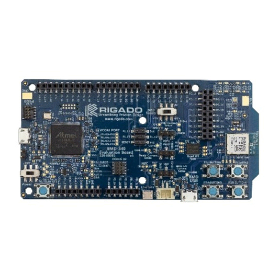
BMD-34 EVK - User guide Hardware description Design files for each of the BMD-3xx evaluation boards may be requested from the u-blox support team. Figure 2: Assembly drawing (Top view) 2.1 Power The BMD-34 evaluation board has five possible power sources as listed below: •... -
Page 7: Usb Peripheral Power
BMD-34 EVK - User guide 2.1.2 USB peripheral power VBUS Power from the USB Peripheral interface on the BMD-340 may be used to power the BMD-340-EVAL by moving SW7 to the “HV” setting. This enables the internal high-voltage regulator (LDO or DC-DC). When in the HV setting, the power switch SW6 should be left in the OFF position, especially if any of the protection diodes are bypassed. - Page 8 BMD-34 EVK - User guide When the reset button is directly connected to P0.18, it can be used as a fifth user button or as a reset button directly connected to the BMD-34 module. Solder jumper J18 is used to connect P0.18 of the BMD-34 module to the RESET_N net (noted as nRESET in Figure 4 below).
-
Page 9: Buttons
BMD-34 EVK - User guide 2.3 Buttons The evaluation board has four user buttons: Button 1, Button 2, Button 3, and Button 4. All buttons are active low; they will connect to ground when pressed. The button GPIO pins must be configured with internal pull-up resistors for proper operation when using the user buttons. -
Page 10: Virtual Com Port
BMD-34 EVK - User guide 2.5 Virtual COM port The evaluation board allows for easy serial communication with the BMD-34 series modules and a connected computer. The Interface IC provides a virtual COM port USB device that connects to four GPIO pins on the module, allowing for UART communication with or without hardware flow control. -
Page 11: Current Sensing Headers
BMD-34 EVK - User guide 2.8 Current sensing headers The evaluation board provides two current sensing headers. “JBMD” allows for power consumption measurement of the BMD-34 module and “JSHD” allows for power consumption measurement of the shields connected to the Arduino-style headers (“VSHLD” power only). Each 3-pin 2.54 mm pitch header has two pins connected across a 1 Ω... -
Page 12: Qspi
BMD-34 EVK - User guide • EXT_GND_DETECT is used by the debug interface to detect the presence of an external target hardware. Connect EXT_GND_DETECT to GND on the target hardware. • Connect GND to GND on the target hardware. • Connect EXT_SWDIO to SWDIO and EXT_SWCLK to SWDCLK on the target BMD-34 module. -
Page 13: Header Pin-Out
BMD-34 EVK - User guide Figure 12: GPIO jumpers 2.12 Header pin-out Headers J5 - J9 and J11 break out the IO signals from the BMD-34 module on 2.54 mm pitch headers. Figure 13: BMD-340 evaluation board pin-out ⚠ The I/O pins of the BMD-34 EVK are not 5 V tolerant. Arduino Uno® style shields shall be configured to use +3.3 V DC (VSHLD) as the I/O voltage reference. - Page 14 BMD-34 EVK - User guide Pin name nRF52840 Function P0.27 P0.27 GPIO P0.26 P0.26 GPIO P0.02 P0.02 GPIO / AIN0 Ground P1.15 P1.15 GPIO P1.14 P1.14 GPIO P1.13 P1.13 GPIO P1.12 P1.12 GPIO P1.11 P1.11 GPIO P1.10 P1.10 GPIO Table 4: Header J6 Pin name nRF52840 Function...
- Page 15 BMD-34 EVK - User guide Pin name nRF52840 Function P0.11 P0.11 GPIO / TRACED[2] P0.12 P0.12 GPIO / TRACED[1] P0.13 P0.13 GPIO P0.14 P0.14 GPIO P0.15 P0.15 GPIO P0.16 P0.16 GPIO P0.17 P0.17 OPEN / GPIO / QSPI CS P0.18 P0.18 RESET_N / GPIO P0.19...
-
Page 16: Setting Up The Evaluation Board
BMD-34 EVK - User guide Setting up the evaluation board This section provides information on how to set up and program the BMD-340 evaluation kit with an example application. 3.1 Set up the tool chain 1. Install SEGGER Embedded Studio request a license. - Page 17 BMD-34 EVK - User guide ☞ The status LED, D5, will flash and then turn solid once the USB device is enumerated. Some flickering is normal. 3. After a few seconds, the computer will recognize the evaluation board as a J-Link device and install the USB-Virtual COM Port device driver.
-
Page 18: Open An Example Project
BMD-34 EVK - User guide 10. While still in the J-Link Commander session, save the pre-programmed public Bluetooth savebin mac_addr.bin 0x10001080 8 address by typing in: mac_addr.bin 11. Save the file to a convenient location for future use. exit. 12. Exit the J-Link session by typing mac_addr.bin At this point, a file titled will be saved in the current directory. -
Page 19: Related Documents
BMD-34 EVK - User guide Related documents BMD-340 data sheet, doc. no. UBX-19033353 BMD-341 data sheet, doc. no. UBX-19033643 Nordic nRF52840 product specification S140 SoftDevice specification u-blox package information guide, doc. no. UBX-14001652 ☞ For regular updates to u-blox documentation and to receive product change notifications, register on our homepage (www.u-blox.com). -
Page 20: Contact
BMD-34 EVK - User guide Contact For complete contact information, visit us at www.u-blox.com. u-blox Offices North, Central and South America Headquarters Asia, Australia, Pacific Europe, Middle East, Africa u-blox America, Inc. u-blox Singapore Pte. Ltd. u-blox AG Phone: +1 703 483 3180 Phone: +65 6734 3811 E-mail:...
Need help?
Do you have a question about the BMD-34 EVK Series and is the answer not in the manual?
Questions and answers