Advertisement
Quick Links
INSTALLATION INSTRUCTIONS
FireLock
®
Residential Zone Control Riser Module Assembly
SERIES 247
• Read and understand all instructions before attempting to install any Victaulic products.
• Depressurize and drain the piping system before attempting to install, remove, adjust, or maintain
any Victaulic products.
• Wear safety glasses, hardhat, and foot protection when working with Victaulic piping products.
Failure to follow these instructions could result in serious personal injury and/or property damage.
Water ow
Detector
Module Body
From Water
Supply
To Building Drain
Test/Drain Valve
INSTALLATION OF THE SERIES 247
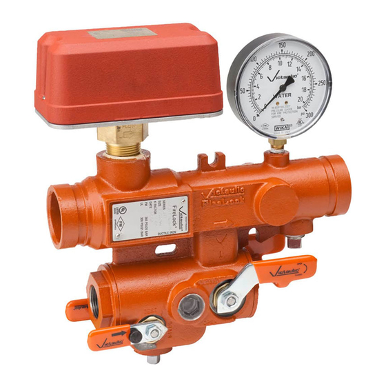
The Series 247 FireLock Residential Zone Control Riser Module
includes the module body, a UL or ULC Listed and FM Approved
waterflow detector, a pressure gauge with shutoff valve (provision for
draining), and an alarm test module available with different orifice sizes
(K-factors). In addition, an optional pressure relief valve kit is available.
Refer to the "Installation of the Optional Pressure Relief Valve Kit"
section.
NOTE CONCERNING WATERFLOW DETECTOR INSTALLATION AND
MAINTENANCE INSTRUCTIONS VERSUS RISER MANIFOLDS, AS
STATED FROM THE WATERFLOW DETECTOR MANUFACTURER: "The
section 'Installation Guidelines' suggests mounting the detector at least
6 inches/152 mm from a fitting that changes the direction of water flow
and no less than 24 inches/610 mm from a valve or drain. This is a
general statement that is superseded when a riser manifold assembly
is listed or approved by agencies such as UL and/or FM. The agency
approval takes precedence because this configuration has been tested
and its operation validated."
NOTICE
• The Series 247 can be installed in either the horizontal
(left-to-right or right-to-left flow) or vertical (up) position.
The flow direction arrow MUST point toward the
sprinkler distribution, as shown in the drawing above.
www.victaulic.com
VICTAULIC IS A REGISTERED TRADEMARK OF VICTAULIC COMPANY. © 2012 VICTAULIC COMPANY. ALL RIGHTS RESERVED. PRINTED IN THE USA.
REV_C
WARNING
Pressure Gauge
Shuto Valve
1 - 2-inch/33.7 - 60.3-mm Sizes
1.
2.
3.
4.
5.
6.
To Sprinkler
Distribution
Shuto Valve
Install the Series 247 into the system using Victaulic couplings for
grooved-end pipe. Always refer to the instructions, supplied with
the coupling, for complete installation requirements.
For the NPT threaded drain outlet, follow standard piping practices
to make the threaded connection. NOTE: The nominal drain size is
1 inch/25 mm. The drawings, shown on page 2, provide examples
of alternative ways to make the threaded drain connection with
a street elbow to avoid interference with couplings on the water
supply side and sprinkler distribution side of the module body.
Apply thread sealant to the threads of the pressure gauge. Install
the pressure gauge into the module body, as shown in the drawing
above. Make sure the face of the gauge is visible.
Connect the water-flow detector to the alarm system in accordance
with the instructions supplied.
To install the optional pressure relief valve, follow the instructions
in the "Installation of the Optional Pressure Relief Valve Kit"
section.
Perform the system flow test, as outlined in the "System Flow
Test" section.
I-247
Pressure
Gauge
I-247_1
Advertisement

Related Manuals for Victaulic FireLock 247 Series


Summary of Contents for Victaulic FireLock 247 Series
- Page 1 (left-to-right or right-to-left flow) or vertical (up) position. The flow direction arrow MUST point toward the sprinkler distribution, as shown in the drawing above. www.victaulic.com VICTAULIC IS A REGISTERED TRADEMARK OF VICTAULIC COMPANY. © 2012 VICTAULIC COMPANY. ALL RIGHTS RESERVED. PRINTED IN THE USA. REV_C I-247_1...
- Page 2 Turn the thumb screw on the handle of the “Test/Drain Valve” counterclockwise. Place the handle of the “Test/Drain Valve” in the “Test” position. www.victaulic.com VICTAULIC IS A REGISTERED TRADEMARK OF VICTAULIC COMPANY. © 2012 VICTAULIC COMPANY. ALL RIGHTS RESERVED. PRINTED IN THE USA. REV_C I-247_2...
- Page 3 (left-to-right or right-to-left flow) or vertical (up) position. The pressure relief valve is rated to 175 psi/1206 kPa. www.victaulic.com VICTAULIC IS A REGISTERED TRADEMARK OF VICTAULIC COMPANY. © 2012 VICTAULIC COMPANY. ALL RIGHTS RESERVED. PRINTED IN THE USA. REV_C I-247_3...
- Page 4 Residential Zone Control Riser Module Assembly SERIES 247 For complete contact information, visit www.victaulic.com I-247 5375 REV C UPDATED 02/2012 Z000247000 VICTAULIC IS A REGISTERED TRADEMARK OF VICTAULIC COMPANY. © 2012 VICTAULIC COMPANY. ALL RIGHTS RESERVED. PRINTED IN THE USA. I-247...
Need help?
Do you have a question about the FireLock 247 Series and is the answer not in the manual?
Questions and answers