Table of Contents
Advertisement
Quick Links
INSTALLATION, MAINTENANCE, AND TESTING MANUAL
Victaulic
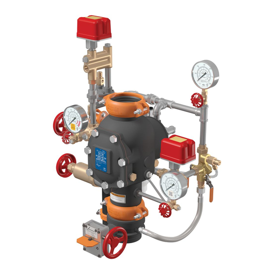
Series 769N FireLock NXT
®
Double-Interlocked Pneumatic/Pneumatic Release with Series 798 Pneumatic/Pneumatic Actuator
• Read and understand all instructions before attempting to install, remove, adjust, or perform maintenance on any Victaulic piping products.
• Depressurize and drain piping systems before attempting to install, remove, adjust, or perform maintenance on any Victaulic piping
products.
• Wear safety glasses, hardhat, and foot protection.
• Save this installation, maintenance, and testing manual for future reference.
Failure to follow instructions and warnings could cause system failure, resulting in death or serious personal injury and property damage.
REV_A
I-769N.Preaction/DPA
™
Actuated Valve with Preaction Trim
WARNING
KEEP THESE INSTRUCTIONS WITH THE
INSTALLED VALVE FOR FUTURE REFERENCE
I-769N.Preaction/DPA
Advertisement
Table of Contents

Related Manuals for Victaulic FireLock NXT 769N Series


Summary of Contents for Victaulic FireLock NXT 769N Series
- Page 1 WARNING • Read and understand all instructions before attempting to install, remove, adjust, or perform maintenance on any Victaulic piping products. • Depressurize and drain piping systems before attempting to install, remove, adjust, or perform maintenance on any Victaulic piping products.
- Page 2 SERIES 769N FIRELOCK NXT ACTUATED VALVE ™ WITH DOUBLE-INTERLOCKED PNEUMATIC/ PNEUMATIC RELEASE PREACTION TRIM THIS QUICK REFERENCE SECTION IS FOR PLACING THE SYSTEM IN SERVICE AND FOR PERFORMING WATER FLOW ALARM TESTS. AN EXPERIENCED, TRAINED INSTALLER MUST READ AND UNDERSTAND THE FULL CONTENTS OF THIS MANUAL AND ALL WARNING MESSAGES BEFORE ATTEMPTING TO PLACE THE SYSTEM INTO SERVICE.
- Page 3 NORMAL OPERATING POSITIONS FOR VALVES Valve Normal Operating Position Valve Normal Operating Position Water Supply Main Control Valve Open Pilot Line Fill Valve Closed – Restricted Fill Water Supply Main Drain Valve Closed System Line Shut-Off Valve Open System Main Drain Valve Closed System Line Fill Valve Closed –...
-
Page 4: Table Of Contents
When an uninterrupted water flow alarm is required, Victaulic recommends the use of a low-pressure alarm NOTICE installed on the charge line downstream of the priming manifold •... -
Page 5: Hydrostatic Testing
50 psi/345 kPa/3.4 Bar air pressure. Failure to follow this instruction could result in death or serious personal injury and property Install the valve assembly into the riser with two Victaulic rigid damage. couplings. Refer to the instructions, supplied with the coupling, for complete installation requirements. -
Page 6: Trim Dimensions
I-769N.Preaction/DPA / Victaulic Series 769N FireLock NXT ™ / Installation, Maintenance, and Testing Manual ® TRIM DIMENSIONS A 4-INCH/114.3-MM VALVE WITH DOUBLE-INTERLOCKED PNEUMATIC/PNEUMATIC RELEASE PREACTION TRIM IS SHOWN BELOW 1 1/2 – 2-INCH/48.3 – 60.3-MM CONFIGURATIONS CONTAIN 3/4-INCH/19-MM DRAIN VALVES 2 1/2 –... -
Page 7: Trim Components - Exploded View Drawing
I-769N.Preaction/DPA / Victaulic Series 769N FireLock NXT ™ / Installation, Maintenance, and Testing Manual ® TRIM COMPONENTS – EXPLODED VIEW DRAWING Series 769N FireLock NXT Actuated Valve - Double-Interlocked Pneumatic/Pneumatic Release Preaction Trim with Series 798 Pneumatic/Pneumatic Actuator When installing the optional Series 746-LPA Dry Accelerator, relocate the auto vent to the location of the indicated plug. -
Page 8: Internal Valve Components - Section View And Exploded View Drawings
I-769N.Preaction/DPA / Victaulic Series 769N FireLock NXT ™ / Installation, Maintenance, and Testing Manual ® INTERNAL VALVE COMPONENTS – SECTION VIEW AND EXPLODED VIEW DRAWINGS Clapper Latch Diaphragm Assembly Clapper Seal Seat Exaggerated for Clarity Valve is shown in the “set” position The 1½-inch/48.3-mm and 2-inch/60.3-mm valve sizes contain washers under the heads of the cover plate bolts. -
Page 9: Air Supply Requirements
The “off” or “high” pressure setting should be 18 psi/124 kPa/1.2 Bar. When a base- or riser-mounted air compressor supplies air to a Series 769N FireLock NXT Actuated Valve, it is not necessary to install the Victaulic Series 757 Regulated Air Maintenance Trim Assembly (AMTA). In this case, the air line of the compressor connects to the trim at the fitting where the Series 757 Regulated AMTA is installed normally (refer to the applicable trim drawing). -
Page 10: Initial System Setup
I-769N.Preaction/DPA / Victaulic Series 769N FireLock NXT ™ / Installation, Maintenance, and Testing Manual ® SECTION I • Initial System Setup I-769N.Preaction/DPA_10 REV_A... - Page 11 I-769N.Preaction/DPA / Victaulic Series 769N FireLock NXT ™ / Installation, Maintenance, and Testing Manual ® INITIAL SYSTEM SETUP Step 6: NOTICE When pilot pressure reaches approximately 10 psi/69 kPa/0.7 Bar, pull up on the pilot chamber Auto Vent Sleeve, which is located on the air •...
- Page 12 I-769N.Preaction/DPA / Victaulic Series 769N FireLock NXT ™ / Installation, Maintenance, and Testing Manual ® INITIAL SYSTEM SETUP (CONTINUED) Step 12: Step 17: Open the charge line ball valve. Allow water to flow through the auto Open the water supply main control valve fully.
- Page 13 I-769N.Preaction/DPA / Victaulic Series 769N FireLock NXT ™ / Installation, Maintenance, and Testing Manual ® WARNING • It is critical for the pilot line and system line shut-off valves and fill valves to be in the proper operating orientations, as shown below.
-
Page 14: Resetting The System
I-769N.Preaction/DPA / Victaulic Series 769N FireLock NXT ™ / Installation, Maintenance, and Testing Manual ® SECTION II • Resetting the System I-769N.Preaction/DPA_14 REV_A... - Page 15 I-769N.Preaction/DPA / Victaulic Series 769N FireLock NXT ™ / Installation, Maintenance, and Testing Manual ® RESETTING THE SYSTEM Step 1: Step 5: Isolate the charge line ball valve by placing it in the closed position. Confirm that all system drains are shut and that the system is free from leaks.
-
Page 16: Weekly External Inspection
I-769N.Preaction/DPA / Victaulic Series 769N FireLock NXT ™ / Installation, Maintenance, and Testing Manual ® SECTION III • Weekly External Inspection • Monthly External Inspection WARNING • The building owner or their representative is responsible for maintaining the fire protection system in proper operating condition. - Page 17 I-769N.Preaction/DPA / Victaulic Series 769N FireLock NXT ™ / Installation, Maintenance, and Testing Manual ® WEEKLY EXTERNAL INSPECTION MONTHLY EXTERNAL INSPECTION Record the system air pressure and water supply pressure. CAUTION Confirm that the water supply pressure is within the range of normal pressures observed in the area.
-
Page 18: Required Main Drain Test
I-769N.Preaction/DPA / Victaulic Series 769N FireLock NXT ™ / Installation, Maintenance, and Testing Manual ® SECTION IV • Required Main Drain Test • Required Water Flow Alarm Test • Required Water Level and Low- Air Alarm Tests • Required Partial Operational Trip Test •... - Page 19 I-769N.Preaction/DPA / Victaulic Series 769N FireLock NXT ™ / Installation, Maintenance, and Testing Manual ® REQUIRED MAIN DRAIN TEST Perform the main drain test on a frequency required by the current 10. Compare the residual pressure reading, taken above, to the NFPA-25 code.
- Page 20 I-769N.Preaction/DPA / Victaulic Series 769N FireLock NXT ™ / Installation, Maintenance, and Testing Manual ® REQUIRED WATER FLOW ALARM TEST Perform the water flow alarm test on a frequency required by the Open the water supply main drain valve fully to flush the water current NFPA-25 code.
-
Page 21: Required Water Level And Low-Air Alarm Tests For The System Supervisory Switch
I-769N.Preaction/DPA / Victaulic Series 769N FireLock NXT ™ / Installation, Maintenance, and Testing Manual ® REQUIRED WATER LEVEL AND LOW AIR ALARM TESTS FOR THE SYSTEM SUPERVISORY SWITCH Close the water supply main drain valve. Perform the water level and low air alarm tests for the system supervisory switch on a frequency required by the current NFPA-25 Close the water supply main control valve. - Page 22 I-769N.Preaction/DPA / Victaulic Series 769N FireLock NXT ™ / Installation, Maintenance, and Testing Manual ® REQUIRED WATER LEVEL AND LOW AIR ALARM TESTS FOR THE SYSTEM SUPERVISORY SWITCH (CONTINUED) 13. Open the water supply main drain valve. Valve Normal Operating Position...
-
Page 23: Required Water Level And Low-Air Alarm Tests For The Pilot Supervisory Switch
I-769N.Preaction/DPA / Victaulic Series 769N FireLock NXT ™ / Installation, Maintenance, and Testing Manual ® REQUIRED WATER LEVEL AND LOW AIR ALARM TESTS FOR THE PILOT SUPERVISORY SWITCH Close the water supply main drain valve. Close the water supply main control valve. - Page 24 I-769N.Preaction/DPA / Victaulic Series 769N FireLock NXT ™ / Installation, Maintenance, and Testing Manual ® REQUIRED WATER LEVEL AND LOW AIR ALARM TESTS FOR THE PILOT SUPERVISORY SWITCH (CONTINUED) 13. Open the water supply main drain valve. Valve Normal Operating Position...
-
Page 25: Required Partial Operational Trip Test
Remove pressure from the pilot line by pressing down on the Victaulic recommends performing the partial operational (trip) test screw of the pilot chamber Auto Vent Sleeve, which is located annually (at minimum). -
Page 26: Required Full Operational Trip Test
/ Installation, Maintenance, and Testing Manual ® REQUIRED FULL OPERATIONAL TRIP TEST Victaulic recommends the full operational (trip) test every 3 years (at Record the following: minimum). NOTE: The frequency of the full operational (trip) test must 7a. The time between opening the remote system test valve be increased in the presence of contaminated water supplies, corrosive/ (inspector’s test connection) and operation of the actuated... - Page 27 I-769N.Preaction/DPA / Victaulic Series 769N FireLock NXT ™ / Installation, Maintenance, and Testing Manual ® This page intentionally left blank REV_A I-769N.Preaction/DPA_27...
-
Page 28: Required Internal Inspection
I-769N.Preaction/DPA / Victaulic Series 769N FireLock NXT ™ / Installation, Maintenance, and Testing Manual ® SECTION V • Required Internal Inspection WARNING • Depressurize and drain the piping system before attempting to remove the cover plate from the valve. • The building owner or their representative is responsible for maintaining the fire protection system in proper operating condition. - Page 29 16. While the clapper is rotated out of the valve body, pull the latch forward to inspect the diaphragm. If the diaphragm shows any signs of wear or damage, replace it with a new, Victaulic-supplied diaphragm. Refer to the “Removing and Replacing the Diaphragm”...
- Page 30 I-769N.Preaction/DPA / Victaulic Series 769N FireLock NXT ™ / Installation, Maintenance, and Testing Manual ® SECTION VI • Removing and Replacing the Clapper Seal • Removing and Replacing the Clapper Assembly • Installing the Cover Plate Gasket and Cover Plate •...
-
Page 31: Removing And Replacing The Clapper Seal
Pry the clapper seal, along with the seal ring, out of the clapper. Inspect the clapper seal. If the clapper seal is torn or worn, replace it with a new, Victaulic-supplied clapper seal. If replacing the clapper seal assembly with a new assembly, skip to step 7. -
Page 32: Removing And Replacing The Clapper Assembly
I-769N.Preaction/DPA / Victaulic Series 769N FireLock NXT ™ / Installation, Maintenance, and Testing Manual ® REQUIRED SEAL ASSEMBLY BOLT/BOLT SEAL TORQUES Nominal Size Required Torque inches or mm inch-lbs/N•m 1 ½ 2 ½ 76.1 mm 165.1 mm Install the clapper seal into the clapper carefully. Ensure that the seal ring snaps into the clapper completely. -
Page 33: Installing The Cover Plate Gasket And Cover Plate
Verify that the cover plate gasket is in good condition. If the gasket is torn or worn, replace it with a new, Victaulic-supplied gasket. Align the holes of the cover plate gasket with the holes in the cover plate. -
Page 34: Removing And Replacing The Diaphragm Assembly
I-769N.Preaction/DPA / Victaulic Series 769N FireLock NXT ™ / Installation, Maintenance, and Testing Manual ® REMOVING AND REPLACING THE DIAPHRAGM CAUTION Remove the system from service by following steps 1 – 11 of the • DO NOT over-tighten the cover plate bolts. -
Page 35: Cleaning The Cartridge In The Air And Priming Manifold Assemblies
Failure to follow this instruction could cause improper valve operation, resulting in property damage. Use only a new, Victaulic-supplied filter. Install the new filter onto the filter adapter, as shown above. Make sure the o-ring is positioned on the filter adapter, as shown above. -
Page 36: Troubleshooting
I-769N.Preaction/DPA / Victaulic Series 769N FireLock NXT ™ / Installation, Maintenance, and Testing Manual ® SECTION VII • Troubleshooting I-769N.Preaction/DPA_36 REV_A... - Page 37 The Series 798 Pneumatic/Pneumatic Actuator has a broken seal. If the above procedure does not work, contact Victaulic. Water is leaking through the Series 798 Pneumatic/Pneumatic The air chamber of the Series 798 Pneumatic/Pneumatic Actuator is not set. Ensure that the auto vent seals of the Series 798 Pneumatic/Pneumatic Actuator.
- Page 38 For complete contact information, visit victaulic.com I-769N.Preaction/DPA 9450 REV A UPDATED 05/2016 ZDPA769NP0 VICTAULIC AND FIRELOCK NXT ARE REGISTERED TRADEMARKS OR TRADEMARKS OF VICTAULIC COMPANY AND/OR ITS AFFILIATED ENTITIES IN THE UNITED STATES AND/OR OTHER COUNTRIES. © 2016 VICTAULIC COMPANY. ALL RIGHTS RESERVED.
Need help?
Do you have a question about the FireLock NXT 769N Series and is the answer not in the manual?
Questions and answers