Table of Contents
Advertisement
Quick Links
INSTALLATION, MAINTENANCE, AND TESTING MANUAL
Victaulic
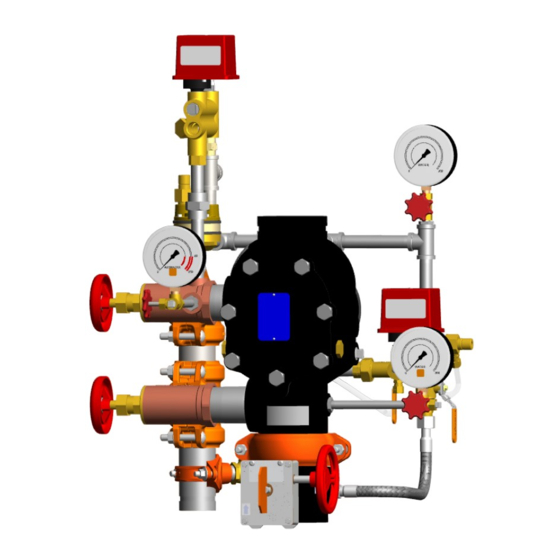
Series 769N FireLock NXT
®
Non-Interlocked Pneumatic Release with Series 776 Low-Pressure Actuator
Non-Interlocked Pneumatic/Electric Release with Series 776 Low-Pressure Actuator and 24 VDC Normally-Closed
Solenoid Valve
Single-Interlocked Pneumatic Release with Series 776 Low-Pressure Actuator
Single-Interlocked Electric Release with 24 VDC Normally-Closed Solenoid Valve
Double-Interlocked Electric (Electric-Pneumatic/Electric) Release with 24 VDC Normally-Closed Solenoid Valve
Electric Release with 24 VDC Normally-Closed Solenoid Valve and Redundant Solenoid Valve
• Series 769N FireLock NXT
installed in accordance with current, applicable National Fire Protection Association (NFPA 13, 13D, 13R, etc.) standards, or equivalent
standards, and in accordance with applicable building and fire codes. These standards and codes contain important information regarding
protection of systems from freezing temperatures, corrosion, mechanical damage, etc.
• These installation instructions are intended for an experienced, trained installer. The installer shall understand the use of this product and
why it was specified for the particular application.
• The installer shall understand common industry safety standards and potential consequences of improper product installation.
Failure to follow installation requirements and local and national codes and standards could compromise system integrity or cause system
failure, resulting in death or serious personal injury and property damage.
REV_B
• Read and understand all instructions before attempting to install any Victaulic products.
• Always verify that the piping system has been completely depressurized and drained
immediately prior to installation, removal, adjustment, or maintenance of any Victaulic
products.
• Wear safety glasses, hardhat, and foot protection.
Failure to follow these instructions could result in death or serious personal injury and property
damage.
™
Actuated Valves with Preaction Trim shall be used only in fire protection systems that are designed and
™
Actuated Valve with Preaction Trim
Single-Interlocked Pneumatic Release Trim Shown
WARNING
I-769N.Preaction
KEEP THESE INSTRUCTIONS WITH THE
INSTALLED VALVE FOR FUTURE REFERENCE
Scan QR Code for Access to Videos
and Additional Publications
I-769N.Preaction
Advertisement
Table of Contents

Subscribe to Our Youtube Channel
Related Manuals for Victaulic I-769N


Summary of Contents for Victaulic I-769N
- Page 1 Single-Interlocked Pneumatic Release Trim Shown WARNING • Read and understand all instructions before attempting to install any Victaulic products. • Always verify that the piping system has been completely depressurized and drained immediately prior to installation, removal, adjustment, or maintenance of any Victaulic products.
- Page 2 Confirm that all valves are in their normal operating positions (refer to the table below). NORMAL OPERATING POSITIONS FOR VALVES Valve Normal Operating Position Valve Normal Operating Position Slow-Fill Ball Valve of the Victaulic AMTA Water Supply Main Control Valve Open Open (if applicable) Water Supply Main Drain Valve (Lower...
- Page 3 Auto Drain Sleeve Auto Vent Sleeve of Series 776 Low-Pressure Actuator Ball Drip Plunger Water Supply Charge Main Control Line Ball Valve Valve Water Supply Main Drain Valve Alarm Test Ball Valve Single-Interlocked Pneumatic Release Trim Shown REQUIRED WATER FLOW ALARM TEST Refer to NFPA 25, FM Datasheets, LPCB/EN guidelines, or any other applicable local and national requirements to perform water flow alarm tests.
-
Page 4: Table Of Contents
SECTION III removal, adjustment, or maintenance of any Victaulic products. Daily/Weekly Inspection ....... . . 20 Failure to follow these instructions can cause product failure, Monthly Inspection . -
Page 5: Important Installation Information
Series 75D Water Column Device kit Install the valve assembly into the riser with two Victaulic rigid is available to assist in a utomatically draining water out of the riser. -
Page 6: Series 776 Low-Pressure Actuator
I-769N.Preaction / Victaulic Series 769N FireLock NXT ™ / Installation, Maintenance, and Testing Manual ® The components shaded in orange below are shipped separate from the valve and shall be installed in accordance with the trim drawing provided. NOTE: The Vic-Quick Riser (VQR) assembly is shown. - Page 7 I-769N.Preaction / Victaulic Series 769N FireLock NXT ™ / Installation, Maintenance, and Testing Manual ® The components shaded in orange below are shipped separate from the valve and shall be installed in accordance with the trim drawing provided. NOTE: The Vic-Quick Riser (VQR) assembly is shown.
- Page 8 I-769N.Preaction / Victaulic Series 769N FireLock NXT ™ / Installation, Maintenance, and Testing Manual ® TRIM DIMENSIONS A 4-INCH/114.3-MM VALVE WITH SINGLE-INTERLOCKED PNEUMATIC RELEASE PREACTION TRIM IS SHOWN BELOW 1 1/2 – 2-INCH/48.3 – 60.3-MM CONFIGURATIONS CONTAIN 3/4-INCH/19-MM DRAIN VALVES 2 1/2 –...
-
Page 9: Trim Components - Exploded View Drawing
Auto Vent Sleeve of Series 776 Low-Pressure Actuator Victaulic Air Maintenance Trim Assembly (AMTA) Series 746-LPA Dry Accelerator Slow-Fill Ball Valve of the Victaulic AMTA Series 746-LPA Dry Accelerator 1/4-Turn Vent Ball Valve Fast-Fill Ball Valve of the Victaulic AMTA... -
Page 10: Trim Components - Exploded View Drawing
Water Supply Pressure Gauge/Gauge Valve Assembly Air Manifold Victaulic Air Maintenance Trim Assembly (AMTA) Series 776 Low-Pressure Actuator Slow-Fill Ball Valve of the Victaulic AMTA Auto Vent Sleeve of Series 776 Low-Pressure Actuator Fast-Fill Ball Valve of the Victaulic AMTA I-769N.Preaction_7... - Page 11 Water Supply Pressure Gauge/Gauge Valve Assembly Air Supervisory Pressure Switch Victaulic Air Maintenance Trim Assembly (AMTA) Air Manifold Slow-Fill Ball Valve of the Victaulic AMTA Series 776 Low-Pressure Actuator Fast-Fill Ball Valve of the Victaulic AMTA Auto Vent Sleeve of Series 776 Low-Pressure Actuator REV_B I-769N.Preaction_8...
- Page 12 I-769N.Preaction / Victaulic Series 769N FireLock NXT ™ / Installation, Maintenance, and Testing Manual ® TRIM COMPONENTS – EXPLODED VIEW DRAWING Series 769N FireLock NXT Actuated Valve - Single-Interlocked Electric and Double-Interlocked Electric (Electric-Pneumatic/Electric) Release Preaction Trim with 24 VDC Normally-Closed Solenoid Valve Gray shaded areas identify components that are provided when the VQR assembly is ordered.
-
Page 13: Trim Components - Exploded View Drawing
I-769N.Preaction / Victaulic Series 769N FireLock NXT ™ / Installation, Maintenance, and Testing Manual ® TRIM COMPONENTS – EXPLODED VIEW DRAWING Series 769N FireLock NXT Actuated Valve - Electric Release Preaction Trim with 24 VDC Normally-Closed Solenoid Valve and Redundant Solenoid Valve Gray shaded areas identify components that are provided when the VQR assembly is ordered. -
Page 14: Internal Valve Components - Section View And Exploded View Drawings
I-769N.Preaction / Victaulic Series 769N FireLock NXT ™ / Installation, Maintenance, and Testing Manual ® INTERNAL VALVE COMPONENTS – SECTION VIEW AND EXPLODED VIEW DRAWINGS Clapper Latch Diaphragm Assembly Clapper Seal Seat Exaggerated for Clarity Valve is shown in the “set” position The 1½-inch/48.3-mm and 2-inch/60.3-mm valve sizes contain washers under the heads of the cover plate bolts. -
Page 15: Air Supply Requirements
If multiple Series 769N FireLock NXT Actuated Valves with pneumatic release preaction trim are installed with a common air supply, isolate the systems with a Victaulic spring-loaded, soft-seated ball check valve to ensure air integrity for each system. Good practice is to include a ball valve for isolation and service of each individual system. -
Page 16: Initial System Setup
I-769N.Preaction / Victaulic Series 769N FireLock NXT ™ / Installation, Maintenance, and Testing Manual ® SECTION I • Initial System Setup I-769N.Preaction_13 REV_B... - Page 17 I-769N.Preaction / Victaulic Series 769N FireLock NXT ™ / Installation, Maintenance, and Testing Manual ® INITIAL SYSTEM SETUP Step 4: For single-interlocked electric and double-interlocked electric (electric- NOTICE pneumatic/electric) release trim, open the charge line ball valve. Allow water to flow through the auto drain tube, then proceed to step E5a.
- Page 18 Step 10: Alarm Test Ball Valve of the Priming Manifold Assembly Closed Open the water supply main control valve fully. Slow-Fill Ball Valve of the Victaulic AMTA (if applicable) Open Step 11: Fast-Fill Ball Valve of the Victaulic AMTA (if applicable)
- Page 19 I-769N.Preaction / Victaulic Series 769N FireLock NXT ™ / Installation, Maintenance, and Testing Manual ® This page intentionally left blank REV_B I-769N.Preaction_16...
-
Page 20: Resetting The System
I-769N.Preaction / Victaulic Series 769N FireLock NXT ™ / Installation, Maintenance, and Testing Manual ® SECTION II • Resetting the System I-769N.Preaction_17 REV_B... - Page 21 I-769N.Preaction / Victaulic Series 769N FireLock NXT ™ / Installation, Maintenance, and Testing Manual ® RESETTING THE SYSTEM Step 5: Confirm that all system drains are shut and that the system is free Step 1: from leaks. Isolate the charge line ball valve by placing it in the closed position.
- Page 22 I-769N.Preaction / Victaulic Series 769N FireLock NXT ™ / Installation, Maintenance, and Testing Manual ® SECTION III • Inspection/Testing Requirements WARNING • The building owner or their representative is responsible for maintaining the fire protection system in proper operating condition.
-
Page 23: Daily/Weekly Inspection
Replace any damaged or corroded parts. Alarm Test Ball Valve of the Priming Manifold Assembly Closed NOTICE Slow-Fill Ball Valve of the Victaulic AMTA (if applicable) Open Fast-Fill Ball Valve of the Victaulic AMTA (if applicable) Closed • If the preaction system is equipped with a low-pressure alarm, Isolation Ball Valve for Series 746-LPA Dry Accelerator monthly inspections may be sufficient. -
Page 24: Required Main Drain Test
I-769N.Preaction / Victaulic Series 769N FireLock NXT ™ / Installation, Maintenance, and Testing Manual ® SECTION IV • Required Main Drain Test • Required Water Flow Alarm Test • Required Water Level and Low- Air Alarm Tests • Required Partial Operational Trip Test •... - Page 25 Verify that the system is at the proper air pressure for the local Alarm Test Ball Valve of the Priming Manifold Assembly Closed water supply pressure. Slow-Fill Ball Valve of the Victaulic AMTA (if applicable) Open CAUTION Fast-Fill Ball Valve of the Victaulic AMTA (if applicable)
- Page 26 I-769N.Preaction / Victaulic Series 769N FireLock NXT ™ / Installation, Maintenance, and Testing Manual ® REQUIRED WATER FLOW ALARM TEST Open the water supply main drain valve (lower drain valve) fully to flush the water supply of any contaminants. Refer to NFPA 25, FM Datasheets, or any applicable local requirements Close the water supply main drain valve (lower drain valve).
-
Page 27: Required Water Level And Low-Air Alarm Tests
Alarm Test Ball Valve of the Priming Manifold Assembly Closed Close the water supply main control valve. Slow-Fill Ball Valve of the Victaulic AMTA (if applicable) Open Partially open the system main drain valve (upper drain valve) Fast-Fill Ball Valve of the Victaulic AMTA (if applicable) Closed slowly. -
Page 28: Low Water Alarm Test
Alarm Test Ball Valve of the Priming Manifold Assembly Closed Close the water supply main control valve. Slow-Fill Ball Valve of the Victaulic AMTA (if applicable) Open 2a. Verify that the water pressure is above 1.4 Bar/20 psi. Fast-Fill Ball Valve of the Victaulic AMTA (if applicable) -
Page 29: Required Partial Operational Trip Test
Relieve pressure from the pilot line Victaulic recommends performing the partial operational (trip) test c. Open the manual pull station valve annually (at minimum). NOTE: The frequency of the partial operational (trip) test shall be increased in the presence of contaminated water Confirm that the charge line’s pressure drops to zero and that... -
Page 30: Required Full Operational Trip Test
Record the following: 6a. The time between opening the remote system test valve Victaulic recommends the full operational (trip) test every 3 years (at (inspector’s test connection) and operation of the actuated minimum). NOTE: The frequency of the full operational (trip) test shall... - Page 31 I-769N.Preaction / Victaulic Series 769N FireLock NXT ™ / Installation, Maintenance, and Testing Manual ® This page intentionally left blank REV_B I-769N.Preaction_28...
-
Page 32: Required Internal Inspection
I-769N.Preaction / Victaulic Series 769N FireLock NXT ™ / Installation, Maintenance, and Testing Manual ® SECTION V • Required Internal Inspection WARNING • Depressurize and drain the piping system before attempting to remove the cover plate from the valve. • The building owner or their representative is responsible for maintaining the fire protection system in proper operating condition. - Page 33 15. While the clapper is rotated out of the valve body, pull the latch forward to inspect the diaphragm. If the diaphragm shows any signs of wear or damage, replace it with a new, Victaulic-supplied diaphragm. Refer to the “Removing and Replacing the Diaphragm”...
- Page 34 I-769N.Preaction / Victaulic Series 769N FireLock NXT ™ / Installation, Maintenance, and Testing Manual ® SECTION VI • Removing and Replacing the Clapper Seal • Removing and Replacing the Clapper Assembly • Installing the Cover Plate Gasket and Cover Plate •...
-
Page 35: Removing And Replacing The Clapper Seal
Pry the clapper seal, along with the seal ring, out of the clapper. Inspect the clapper seal. If the clapper seal is torn or worn, replace it with a new, Victaulic-supplied clapper seal. If replacing the clapper seal assembly with a new assembly, skip to step 7. -
Page 36: Removing And Replacing The Clapper Assembly
I-769N.Preaction / Victaulic Series 769N FireLock NXT ™ / Installation, Maintenance, and Testing Manual ® REQUIRED SEAL ASSEMBLY BOLT/BOLT SEAL TORQUES Nominal Size Required Torque inches or mm inch-lbs/N•m 1 ½ 2 ½ 76.1 mm 165.1 mm Install the clapper seal into the clapper carefully. Verify that the seal ring snaps into the clapper completely. -
Page 37: Installing The Cover Plate Gasket And Cover Plate
Verify that the cover plate gasket is in good condition. If the gasket is torn or worn, replace it with a new, Victaulic-supplied gasket. Align the holes of the cover plate gasket with the holes in the cover plate. -
Page 38: Removing And Replacing The Diaphragm
I-769N.Preaction / Victaulic Series 769N FireLock NXT ™ / Installation, Maintenance, and Testing Manual ® REMOVING AND REPLACING THE DIAPHRAGM CAUTION Remove the system from service by following steps 1 – 10 of the • DO NOT over-tighten the cover plate bolts. -
Page 39: Cleaning The Cartridge In The Air And Priming Manifold Assemblies
Failure to follow this instruction could cause improper valve operation, resulting in property damage. Use only a new, Victaulic-supplied filter. Install the new filter onto the filter adapter, as shown above. Verify that the o-ring is positioned on the filter adapter, as shown above. -
Page 40: Troubleshooting
I-769N.Preaction / Victaulic Series 769N FireLock NXT ™ / Installation, Maintenance, and Testing Manual ® SECTION VII • Troubleshooting • System Sensor* PDRP-2001 or NOTIFIER* RP-2001 Field Wiring Diagrams • Sample Program for System Sensor* PDRP-2001 or NOTIFIER* RP-2001 Panel * System Sensor and NOTIFIER are registered trademarks of Honeywell International, Inc. - Page 41 Actuator. position. The Series 776 Low-Pressure Actuator has a broken seal. If the above procedure does not work, contact Victaulic. Water is leaking through the Series 776 Low-Pressure The air chamber of the Series 776 Low-Pressure Actuator is not set.
- Page 42 I-769N.Preaction / Victaulic Series 769N FireLock NXT ™ / Installation, Maintenance, and Testing Manual ® System Sensor* PDRP-2001 or NOTIFIER* RP-2001 Field Wiring Diagram (Electric, Pneumatic/Electric and Double-Interlocked Electric) SYSTEM SUPERVISORY CIRCUIT SUPPLY ISOLATION WATER FLOW EPS10-2 VALVES SEE NOTES 1, 2 AND 3...
- Page 43 I-769N.Preaction / Victaulic Series 769N FireLock NXT ™ / Installation, Maintenance, and Testing Manual ® System Sensor* PDRP-2001 or NOTIFIER* RP-2001 Field Wiring Diagram (Double-Interlocked Electric-Pneumatic/Electric, Cross-Zoned with Low-Air Switch) SYSTEM SUPERVISORY CIRCUIT SUPPLY ISOLATION WATER FLOW EPS10-2 VALVES 4.7K...
- Page 44 I-769N.Preaction / Victaulic Series 769N FireLock NXT ™ / Installation, Maintenance, and Testing Manual ® SAMPLE PROGRAM FOR SYSTEM SENSOR* Edit Zone 5 PDRP-2001 OR NOTIFIER* RP-2001 PANEL Press 2=INPUT ZONES (DUAL OR SINGLE HAZARD) Press SYSTEM SETUP 2=ZONE 5...
- Page 45 I-769N.Preaction / Victaulic Series 769N FireLock NXT ™ / Installation, Maintenance, and Testing Manual ® DOUBLE KNOCK/CROSS ZONE DETECTION AND Zone Selection-Z2+Z5=RELEASE LOW AIR PRESSURE Press 1=RELEASE 1 GROUP Press “MODE” Press 2=NONE 2=PROGRAMMING MODE Press 2=ZONE 2 Enter Password “00000”...
- Page 46 For complete contact information, visit victaulic.com I-769N.Preaction 9445 REV B UPDATED 06/2022 Z000769NP0 VICTAULIC AND FIRELOCK NXT ARE REGISTERED TRADEMARKS OR TRADEMARKS OF VICTAULIC COMPANY AND/OR ITS AFFILIATED ENTITIES IN THE UNITED STATES AND/OR OTHER COUNTRIES. © 2022 VICTAULIC COMPANY. ALL RIGHTS RESERVED.
Need help?
Do you have a question about the I-769N and is the answer not in the manual?
Questions and answers