Table of Contents
Advertisement
Quick Links
Chapter1 Introduction................................................................................................................................ 1
1.1 General Information.............................................................................................................................3
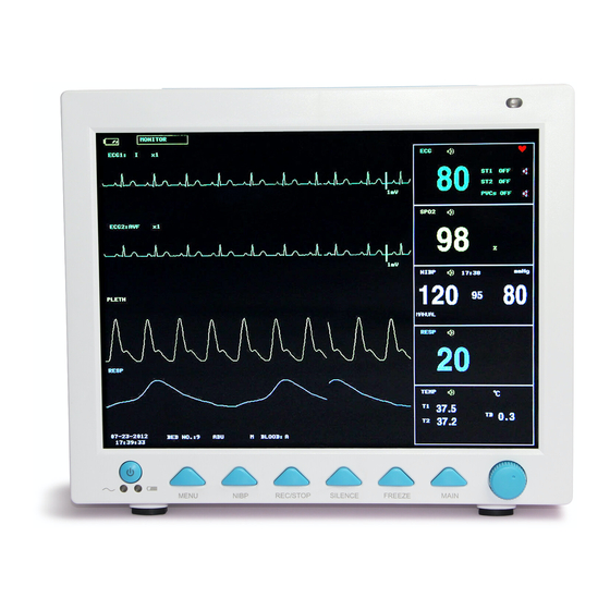
1.2 Screen Display..................................................................................................................................... 4
1.3 Button Functions.................................................................................................................................. 7
1.4 Interfaces.............................................................................................................................................. 8
1.5 Built-in Battery.................................................................................................................................... 10
Chapter2 Getting Started........................................................................................................................ 11
2.1 Open the Package and Check......................................................................................................... 11
2.2 Connect the Power Cables...............................................................................................................11
2.3 Power on the Monitor........................................................................................................................ 11
2.4 Connect Patient Sensors..................................................................................................................12
2.5 Check the Recorder.......................................................................................................................... 12
Chapter3 System Menu.......................................................................................................................... 13
3.1 Patient Information Setup.................................................................................................................13
3.2 Default Setup......................................................................................................................................15
3.3 Trend Review, Measurement Review and Alarm Event Review.................................................16
3.4 System Setup..................................................................................................................................... 16
3.5 Monitor Version.................................................................................................................................. 29
3.6 Drug Calculation................................................................................................................................ 29
3.7 Maintenance....................................................................................................................................... 29
3.8 DEMO function...................................................................................................................................31
Chapter4 Alarm........................................................................................................................................ 32
4.1 Alarm Modes...................................................................................................................................... 32
4.2 Alarm verification during power on..................................................................................................34
4.3 Alarm Cause....................................................................................................................................... 34
4.4 SILENCE and PAUSE.......................................................................................................................35
4.5 Parameter Alarm................................................................................................................................ 35
4.6 When an Alarm Occurs..................................................................................................................... 36
Chapter5 Freeze...................................................................................................................................... 37
5.1 General................................................................................................................................................37
5.2 Enter/Exit Freeze Status...................................................................................................................37
5.3 FREEZE Menu................................................................................................................................... 38
5.4 Reviewing Frozen Waveform........................................................................................................... 38
5.5 Recording Frozen Waveform........................................................................................................... 38
Chapter6 Recording................................................................................................................................ 40
6.1 General Information on Recording..................................................................................................40
6.2 Recording Type.................................................................................................................................. 40
6.3 Recording Startup..............................................................................................................................42
6.4 Recorder Operations and Status Messages..................................................................................43
Chapter7 Trend and Event..................................................................................................................... 46
7.1 Trend Graph....................................................................................................................................... 46
7.2 Trend Table......................................................................................................................................... 47
7.3 NIBP Recall........................................................................................................................................ 48
7.4 Alarm Event Recall............................................................................................................................ 49
Content
Contents s s s
Content
Content
- - - - V - - - -
Advertisement
Table of Contents

Related Manuals for Contec CMS8000


Summary of Contents for Contec CMS8000
-
Page 1: Table Of Contents
Content Content Contents s s s Content Chapter1 Introduction..........................1 1.1 General Information..........................3 1.2 Screen Display............................. 4 1.3 Button Functions..........................7 1.4 Interfaces.............................. 8 1.5 Built-in Battery............................ 10 Chapter2 Getting Started........................11 2.1 Open the Package and Check......................11 2.2 Connect the Power Cables.......................11 2.3 Power on the Monitor........................ - Page 2 Chapter8 Drug Calculation and Titration Table..................51 8.1 Drug Calculation..........................51 8.2 Titration Table............................. 53 Chapter9 Patient Safety..........................54 Chapter10 Care / Cleaning........................56 10.1 System Check..........................56 10.2 General Cleaning..........................57 10.3 Cleaning Agents..........................57 10.4 Sterilization............................58 10.5 Disinfection............................58 Chapter11 ECG/RESP Monitoring......................59 11.1 What Is ECG Monitoring.........................
- Page 3 15.6 Maintenance and Cleaning......................112 Chapter16 CO2 Measuring(optional)....................114 16.1 General............................114 16.2 Monitoring Procedure........................114 16.3 CO2 Menu............................117 16.4 Alarm Information and Prompt.....................120 16.5 Maintenance and Cleaning......................121 Chapter17 Accessories and Ordering Information................122 17.1 ECG Accessories.......................... 122 17.2 SpO2 Accessories.........................122 17.3 NIBP Accessories..........................122 17.4 TEMP Accessories........................
-
Page 4: Chapter1 Introduction
Chapter1 Chapter1 Introduction Introduction Chapter1 Chapter1 Introduction Introduction � � � � ..For an overall introduction to the monitor, please refer to General General General General Information Information Information Information � � � � Screen Screen Display. - Page 5 Warning Warning Warning Warning Devices connected connected to to to to the monitor shall form equipotential system (protectively earthed). Devices Devices Devices connected connected the monitor monitor monitor shall shall shall form form form an an equipotential equipotential equipotential system system system (protectively (protectively...
- Page 6 software software program program program is is is is minimized. minimized. minimized. software software program minimized. C C C C aution aution aution aution At At At At the the end end of of of of its its service service service service life, life,...
- Page 7 and power plug-in are at the rear panel. This monitor is a user-friendly device with operations conducted by a few buttons and a rotary knob on the front panel. Refer to 1.3 Button Functions for details. The visible LEDs are CLASS 1 LED PRODUCT according with EN 60825-1 A11 Oct 1996. The Monitor performs monitoring of: Heart Rate (HR) 2-channel ECG waveforms...
- Page 8 � Patient information include: BED NO Bed number of patient under monitoring Patient type Three options: Adult, Pediatric, Neonate “01-01-2005” Current date “07:11:17” Current time Patient sex, Male or Female BLOOD Patient blood type Other information in the Message Area will appear and disappear together with the reported status. According to the content, the information is divided into: ■...
- Page 9 can also be selected according to the actual requirement. In the IBP waveform area, the waveform scale is displayed. The three dotted lines for each IBP waveform form up to down represent respectively the upper limit scale, reference scale and lower limit scale. The values of these three scales can be set.
- Page 10 Button Functions 1.3 Button Button Button Functions Functions Functions All the operations to the monitor are through the buttons and a knob at the bottom of the screen. The names of the buttons are below them. They are: � � � � MAIN MAIN MAIN MAIN...
- Page 11 Method Method Method to to to to use knob knob knob to to to to operate operate operate screen: screen: Method use the the knob operate on on the the screen: screen: The rectangular mark on the screen that moves with the rotation of the knob is called “cursor”. Operation can be performed at any position at which the cursor can stay.
- Page 12 ④ ① ⑤ ② ⑥ ③ ⑦ Figure Left Side Figure Figure Figure 1-3 1-3 Left Left Left Side Side Side ! This symbol means “BE CAREFUL". Refer to the manual. Indicates that the instrument is IEC 60601-1 Type CF equipment. The unit displaying this symbol contains an F-Type isolated (floating) patient applied part providing a high degree of protection against shock, and is suitable for use during defibrillation.
-
Page 13: Built-In Battery
Warning Warning Warning Warning Through Through network network interface interface only only company company company’ ’ ’ ’ s s s s Cent connected connected Through Through network network interface interface only only our our company Cent Cent Central ral Monitoring Monitoring Monitoring Monitoring System... -
Page 14: Open The Package And Check
C C C C hapter2 hapter2 hapter2 Getting Getting Started Started hapter2 Getting Getting Started Started ■ Open the package and check ■ Connect the power cables ■ Power on the monitor ■ Connect patient sensors ■ Check the recorder N N N N ote ensure that... - Page 15 N N N N ote If If If If the monitor finds fatal error during self-test, self-test, it it it it will will alarm alarm..the monitor monitor monitor finds finds finds any any fatal fatal fatal error error error during during...
-
Page 16: System Setup
C C C C hapter3 hapter3 hapter3 System System Menu Menu hapter3 System System Menu Menu ■ New patient enrolment ■ Default ■ Trend Graph/Table and Alarm Review ■ System Setup ■ Maintenance This monitor features flexible configurations. You can customize monitoring content, waveform sweep speed, sound volume, and output content. - Page 17 DEPT. Department in which the patient receives treatment. CASE NO CASE No. BED NO Patient bed number (Range: 1-100) DOCTOR Name of the doctor. NAME Patient name (Valid characters: A-Z, 0-9 and space bar; Max. length: 12 characters) Patient gender (Available options: "F" for Female, "M" for Male) PAT TYPE Patient type (Available options: ADU, PED, and NEO) ADMIT...
- Page 18 Default Setup 3.2 Default Default Default Setup Setup Setup N N N N ote After After After After s s s s elect elect elect electing ing any any item item item item in in in in this this this this sub-menu sub-menu sub-menu...
- Page 19 Trend Review, Measurement Review Alarm Event Trend Trend Trend Review, Review, Review, Measurement Measurement Measurement Review Review Review and and Alarm Alarm Alarm Event Event Event Review Review Review Review In the “MAIN MENU”, there are [TREND GRAPH], [TREND TABLE], [NIBP RECALL] and [ALARM RECALL] items.
- Page 20 FACE SELECT menu. Figure Figure Figure Figure 3- 3- 3- 3-8 8 8 8 Standard Standard Standard Standard oxyCRG oxyCRG 2.oxyCRG oxyCRG OxyCRG screen is located at the lower part of the waveform area, consisting of the HR trend, the SpO trend, and the RR (respiration rate) trend or the compressed respiration waveform.
- Page 21 3. 3. 3. 3.Trend Trend Trend Trend � Trend graph Trend graphs locate to the right of the corresponding waveforms in the waveform area, and display the trends of one parameter of each module. The parameter labels,as well as their scales, are displayed to the left of the trend graph.
- Page 22 5. 5. 5. 5.V V V V iewBed iewBed iewBed iewBed This monitor can view one parameter waveform and measured data from another patient monitor (viewbed monitor) on the same monitoring network. To enter the following screen, open FACE SELECT menu, select VIEWBED SCREEN, and then select EXIT.
- Page 23 Figure 3-13 3 3 3 Wave Wave Setup Figure Figure Figure 3-1 Wave Wave Setup Setup Setup You can change the waveforms’ displaying position. 3.4. 3.4. 3.4.3 3 3 3 Wave Wave Wave Selec Selec Select t t t 3.4. Wave Selec Select the [WAVE SELECT] in the “SYSTEM SETUP”...
- Page 24 3.4. 3.4. 3.4. 3.4.5 5 5 5 Param Param Param Param Select Select Select Select Select the [PARAM SELECT] item in the “SYSTEM SETUP” menu to call up the following menu: Figure Figure Figure Figure 3- 3- 3- 3-1 1 1 1 6 6 6 6 Param Param Param Param Select...
- Page 25 Alarm. Alarm. information. For detailed information, refer to Chapter Alarm. Alarm. Figure Figure Figure Figure 3- 3- 3- 3-1 1 1 1 8 8 8 8 Alarm Alarm Alarm Alarm Setup Setup Setup Setup You can highlight the [ALARM VOL] item and then turn the knob to set up the alarm volume. There are 7 options:1~7.
- Page 26 continuously print out the waveform or parameter until this button is pushed again. � TIMING REC TIME OFF used to set up the time interval between two recordings. 10 selections are available: “OFF, 10min, 20min, 30min, 40min, 50min, 1hour, 2hours, 3hours and 4hours”. The system will start the recording process according to the selected time interval.
- Page 27 3.4.10 3.4.10 3.4.10 3.4.10 SD SD OPERATE OPERATE OPERATE OPERATE The user can review patient data on the monitor or on PC by SD card.Here only introduce reviewing method on the monitor . Prepare an empty SD card which capacity is at least 2G. The SD card mounted on the monitor can save 480 hours' trend data respectively for HR ,PVCs,ST1,SpO ,PR,RR,T1,T2 ,TD and 72 hours' full-disclosure waveform of ECG .The trend data's resolution is 1 minute.
- Page 28 2 2 2 2 , , , , Insert Insert Insert CARD CARD Insert SD SD CARD CARD If SD CARD has been inserted and works normal ,the prompt "SD is found,please mount" appears. Figure Figure Figure Figure 3- 3- 3- 3-2 2 2 2 3 3 3 3 SD SD CARD CARD CARD...
- Page 29 4 4 4 4 、Review Review Review Review trend trend trend trend Select "REVIEW TREND " in SD CARD OPERATE menu to call up the following menu.In this menu ,you can select which patient you want to review. Figure Figure Figure Figure 3-2 3-26 6 6 6 Patient...
- Page 30 6 6 6 6 、Review Review Review Review trend trend trend trend data data data data Press "REVIEW " in the upper menu,the trend reviewing window pop up as Figure 3-28 ,you can review trend data in table way.The resolution is 1 minute. Figure Figure Figure...
- Page 31 Figure 3-30 0 0 0 SELECT SELECT TIME SPAN Figure Figure Figure 3-3 SELECT SELECT TIME TIME TIME SPAN SPAN SPAN 9 9 9 9 、 Review Review Review Review ECG ECG waveform waveform waveform waveform � The time span of one window is 5s. �...
- Page 32 10、Unmount Unmount Unmount Unmount SD SD card card card card Enter "SD CARD OPERATE" menu,press "UMOUNT DEVICE".You can take out SD card only when the window displays the prompt "unmount SD card successfully,you can take out the card now." Figure Figure Figure Figure 3-33...
- Page 33 Figure Figure Figure Figure 3- 3- 3- 3-35 35 User User User User Maintain Maintain Maintain Maintain For the [LANGUAGE] language, you can set the screen language to “Chinese” or “English”. For the [LEAD NAMING] item:AHA For the [ALM SOUND] item, you can set the alarm volume to “ON” or “OFF”. For the [NET TYPE] item, CMS.
-
Page 34: Demo Function
turning turning monitor monitor next next time, time, this this setup setup will will restore restore value value value of of of of the previous previous time time when when turning turning on on the the monitor monitor next next time, time, this this setup setup will... - Page 35 Chapter4 Chapter4 Alarm Alarm Chapter4 Chapter4 Alarm Alarm This chapter gives general information about the alarm and corresponding remedies. Alarm setup and prompt messages are provided in respective parameter setup sections. Warning Warning Warning Warning When When monitor monitor monitor is is is is powered powered powered system...
- Page 36 Physiological alarm is displayed in the Physiological Alarm area. Most of technical alarms are displayed in the Technical Alarm area. Technical alarms related to NIBP measurement are displayed in the NIBP Technical Alarm area at the bottom of NIBP parameter area. N N N N ote Physiological Physiological...
-
Page 37: Chapter4 Alarm
Figure Figure 4- 4- 4- 4-1 1 1 1 ALARM ALARM SETUP Figure Figure ALARM ALARM SETUP SETUP SETUP � ALARM VOL: which has 7 selections: 1~7. � ALM REC TIME: which has three selections: 8S, 16S, 32S. � ALM PAUSE TIME: refers to the alarm suspension time span, which has three selections: 1MIN, 2MIN, 3MIN. -
Page 38: Parameter Alarm
SILENCE PAUSE 4.4 SILENCE SILENCE SILENCE and and PAUSE PAUSE PAUSE � SILENCE Press the SILENCE button on the panel for more than 1 seconds can shut off all kinds of sounds until the SILENCE button is pressed again. When the system is in SILENCE status, any newly generated alarm will discharge the SILENCE status and make the system give normal status giving audio and visual alarm. - Page 39 When Alarm Occurs 4.6 When When When an an Alarm Alarm Alarm Occurs Occurs Occurs N N N N ote When en an an alarm alarm alarm alarm occurs, occurs, occurs, occurs, you you should should should should always always always always check check...
-
Page 40: General
C C C C hapter5 hapter5 hapter5 Freeze Freeze hapter5 Freeze Freeze � � � � General � � � � Freeze & Unfreeze � � � � Review & Record Frozen Waveforms General General 5.1 General General When monitoring a patient, you may freeze the waveforms of interest so as to view them carefully. Generally you can review maximally 34 seconds of a frozen waveform. -
Page 41: Freeze Menu
FREEZE Menu 5.3 FREEZE FREEZE FREEZE Menu Menu Menu Press the “FREEZE” button on the panel, the FREEZE menu will appear on the bottom part of the screen. At the same time, the system enters the Freeze status. Figure Figure Figure Figure 5-1 5-1 FREEZE... - Page 42 time length is the same as the length of the waveform displayed on the screen. For example, if the speed of a waveform is relatively fast, then it needs shorter time to record it. When recording frozen waveforms, the system is still in the Freeze status. After completion of recording, if required, you may select once more the waveform to be output and select “REC”...
-
Page 43: Chapter6 Recording
C C C C hapter6 hapter6 hapter6 Recording Recording hapter6 Recording Recording � General information on recording � Instructions for configuring and recording � Recording messages General Information Recording 6.1 General General General Information Information Information on on Recording Recording Recording A thermal dot matrices recorder with 48mm wide printout paper is used for the Monitor. - Page 44 N N N N ote If If If If certain certain recording recording is is is is in in in in process, process, another parameter demands alarm recording, recording, it it it it will will only certain certain recording recording process, process, and and another...
-
Page 45: Recording Startup
Titration Titration Titration Titration Table Table Table Table The monitor can print out the messages in the current TITRATION window. Notes Notes Notes Notes on on Recording Recording Recording Recording � Recording texts: Real time Report Periodic Report Para Alarm Report: XXX (name of the alarm parameter) Arrhythmia Report: XXX (Arrhythmia type) Freeze Wave Report Trend Graph... - Page 46 Trend graph recording Pick ”REC” button in the “TREND GRAPH” menu when viewing the trend graph to print out the currently displayed tr-end graph. Trend table recording Pick ”REC” button in the “TREND TABLE” menu when viewing the trend table to printout the currently displayed trend table.
- Page 47 N N N N ote careful careful when when inserting inserting paper. paper. Avoid Avoid damaging damaging thermosensitive thermosensitive print print head. head. Unless Unless when when Be careful careful when when inserting inserting paper. paper. Avoid Avoid damaging damaging the the thermosensitive thermosensitive print printhead.
- Page 48 Error occurs during Shutdown and re-start RECORDER INIT ERR initialization RECORDER INIT Error occurs during Shutdown and re-start ERR1 initialization RECORDER INIT Error occurs during Shutdown and re-start ERR2 initialization RECORDER INIT Error occurs during Shutdown and re-start ERR3 initialization RECORDER INIT Error occurs...
-
Page 49: Trend Graph
C C C C hapter7 hapter7 hapter7 Trend Trend Event Event hapter7 Trend Trend and and Event Event The monitor provides 72-hour trend data of all parameters, storage of 400 NIBP measurement results and 71 alarm events. This chapter gives detailed instruction for review of all data. Trend Graph 7.1 Trend... -
Page 50: Trend Table
To change change change change the the display display display display scale scale scale scale Pick the “ZOOM” button in the lower line to adjust the y-axis scale and thus change the trend curve in proportion. The value beyond maximum value will be represented by the maximum value. obtain obtain trend... -
Page 51: Nibp Recall
Time in response to each group of trend data is displayed at the leftmost list with date in bracket. Marked event corresponds to marking time. Trend data of each parameter is divided into 8 groups. HR, PVCS ST1, ST2 TEMP1, TEMP2, TEMPD , PR IBP1(S/D/M), IBP2(S/D/M) , INS, AwRR... - Page 52 Figure Figure Figure Figure 7- 7- 7- 7-3 3 3 3 NIBP NIBP NIBP NIBP RECALL RECALL RECALL RECALL Data is listed chronologically from the latest to the earliest. 9 measurements can be displayed in one screen. Pick UP-DOWN to view other trend curve up to 400 results. Pick REC to print out all measurement data of NIBP RECALL.
-
Page 53: Alarm Event Recall
ALARM RECALL EVENT In the pull-down list of ALARM RECALL EVENT, the user can select the parameter whose alarm events he wants to review. The selections include ALL(alarm events of all parameters), ECG, RESP, SPO , NIBP, IBP,TEMP,CO After setting up all the review conditions, press the “ALARM RECALL” button to access “ALARM RECALL”... -
Page 54: Chapter8 Drug Calculation And Titration Table
C C C C hapter8 hapter8 hapter8 Drug Drug Calculation Calculation Titration Titration Table Table hapter8 Drug Drug Calculation Calculation and and Titration Titration Table Table This Portable Patient Monitor provides Drug calculation and titration table display functions for fifteen drugs and outputs the content of titration table on the recorder. - Page 55 used used operator operator calculation calculation reference. reference. Instead, Instead, should should enter enter enter a a a a new group group group of of of of used used by by the the operator operator as as the the calculation calculation reference.
-
Page 56: Titration Table
patient patient being being currently currently monitored. monitored. patient patient being being currently currently monitored. monitored. Titration Table 8.2 Titration Titration Titration Table Table Table Access titration table: Access Access Access titration titration titration table: table: table: Select TITRATION item in DRUG CALC menu to enter titration table display. Titration table display for drug is as following: Figure Figure 8- 8- 8- 8-2 2 2 2 TITRATION... -
Page 57: Chapter9 Patient Safety
C C C C hapter9 hapter9 hapter9 Patient Patient Safety Safety hapter9 Patient Patient Safety Safety This Portable Patient Monitor is designed to comply with the International National Safety requirements for medical electrical equipment. This device has floating inputs and is protected against the effects of defibrillation and electrosurgery. - Page 58 Equipotential Equipotential Equipotential Equipotential Grounding Grounding Grounding Grounding Protection class 1 instruments are already included in the protective grounding (protective earth) system of the room by way of grounding contacts in the power plug. For internal examinations on the heart or the brain, the Monitor must have a separate connection to the equipotential grounding system. One end of the equipotential grounding cable (potential equalization conductor) is connected to the equipotential grounding terminal on the instrument rear panel and the other end to one point of the equipotential grounding system.
-
Page 59: System Check
C C C C hapter10 hapter10 hapter10 Care Care Care / / / / Cleaning Cleaning Cleaning hapter10 Care Cleaning 10.1 10.1 System System Check Check 10.1 10.1 System System Check Check Before using the monitor, do the following: ■ check if there is any mechanical damage;... -
Page 60: General Cleaning
10.2 General Cleaning 10.2 10.2 10.2 General General General Cleaning Cleaning Cleaning Warning Warning Warning Warning Before Before Before Before cleaning cleaning cleaning cleaning the the monitor monitor monitor monitor or or or or the the sensor, sensor, sensor, sensor, make make make make sure... -
Page 61: Sterilization
N N N N ote company responsibility effecti veness veness of of of of controlling controlling infectious disease using our company company company has has no no responsibility responsibility responsibility for for the the effecti effecti effectiveness veness controlling controlling infectious infectious infectious disease disease... -
Page 62: Chapter11 Ecg/Resp Monitoring
C C C C hapter11 hapter11 hapter11 ECG/RESP ECG/RESP Monitoring Monitoring hapter11 ECG/RESP ECG/RESP Monitoring Monitoring 11.1 11.1 What What What Is Is Is Is ECG Monitoring Monitoring 11.1 11.1 What ECG Monitoring Monitoring Monitoring the ECG produces a continuous waveform of the patient's cardiac electric activity to enable an accurate assessment of his current physiological state. -
Page 63: Monitoring Procedure
11.3 Monitoring Procedure 11.3 11.3 11.3 Monitoring Monitoring Monitoring Procedure Procedure Procedure 11.3.1 11.3.1 11.3.1 11.3.1 Preparation Preparation Preparation Preparation Prepare the patient's skin prior to placing the electrodes. ■ The skin is a poor conductor of electricity, therefore preparation of the patient's skin is important to facilitate good electrode contact to skin. - Page 64 names in America are RA, LA, RL, LL and V.) America Euro Lead names color Lead names color White Black Yellow Green Green Black brown White Figure Figure 11-1 11-1 Electrode Electrode placement placement 5-lead 5-lead Figure Figure 11-1 11-1 Electrode Electrode placement placement for for 5-lead...
- Page 65 Figure Figure 11-2 11-2 C-electrode C-electrode placement placement 5-lead 5-lead Figure Figure 11-2 11-2 C-electrode C-electrode placement placement for for 5-lead 5-lead set Recommended Recommended Recommended Recommended ECG ECG Lead Lead Lead Lead Placement Placement Placement Placement for for Surgical Surgical Surgical Surgical Patients...
- Page 66 Figure Figure Figure Figure 11-3 11-3 11-3 11-3 ECG ECG lead lead lead lead N N N N ote If If If If a a a a ECG ECG waveform waveform waveform waveform is is is is not not accurate, accurate, accurate, accurate, while...
- Page 67 11.4 Screen Keys 11.4 11.4 11.4 ECG ECG Screen Screen Screen Hot Hot Keys Keys Keys ③ ① ② ④ ⑤ Figure Figure 11-5 11-5 11-5 T T T T he Figure Figure 11-5 he hot hot key key for for ECG Leads of channel 1: 1) The selectable leads are I, II, III, aVR, aVL,aVF, V...
-
Page 68: Ecg Menu
Leads of channel 2: refer to ① for detailed information. Waveform gain of channel 2: refer to ② for detailed information. N N N N ote Pacemaking Pacemaking signal signal detected detected detected is is is is marked marked marked by a a a a "|"... - Page 69 ■ HR FROM ECG, SpO , AUTO and BOTH may detect heart rate. AUTO distinguishes heart rate source according to the quality of signal. By picking ECG, the monitor prompts HR and activates HR beep. By picking , the monitor prompts PULSE and activates pulse beep. BOTH mode displays HR and PR simultaneously, when this item is picked, PR parameter is displayed to the right side of SpO .
- Page 70 information, information, please please refer refer refer to to to to the section: section: ALARM. ALARM. ALARM. In In In In the table, table, type type marked marked information, information, please please refer the section: section: ARR ARR ALARM. the table, table, the the ARR ARR type...
- Page 71 Physiological Physiological alarms: alarms: Physiological Physiological alarms: alarms: Message Cause Alarm level ECG LOST No ECG signal of the patient is detected. HIGH HR TOO HIGH HR measuring value is above the upper alarm limit User-selectable HR TOO LOW HR measuring value is below the lower alarm limit User-selectable Technical Technical...
-
Page 72: St Segment Monitoring
Make sure patient is quiet, the electrodes measuring signal ECG NOISE properly connected greatly interfered. power system well grounded. Prompt Prompt messages messages (include (include general general alerts) alerts) alerts): : : : Prompt Prompt messages messages (include (include general general alerts) Message Cause... - Page 73 the result exceeds set ST HI value or falls below ST LO value. � ALM LEV: used to set up the ST alarm level. There are three selections: HIGH, MED and LOW. � ALM REC: pick "ON" to enable report printing upon ST analysis alarm. �...
- Page 74 R R R R Wave Wave Wave Wave T T T T P P P P } } } } Q Q Q Q Value Value Value Value S S S S +109 -78 ms +109 +109 +109 ms Figure Figure Figure Figure 11-10...
-
Page 75: Arr. Monitoring
ST measuring value of channel 1 is STI TOO LOW User-selectable below the lower alarm limit. ST measuring value of channel 2 is ST2 TOO HIGH User-selectable above the upper alarm limit. ST measuring value of channel 2 is ST2 TOO LOW User-selectable below the lower alarm limit. - Page 76 ARR ANALYSIS ANALYSIS ANALYSIS ANALYSIS Menu Menu Menu Menu Figure Figure Figure Figure 11-11 11-11 11-11 11-11 ARR ARR ANALYSIS ANALYSIS ANALYSIS ANALYSIS Menu Menu Menu Menu ■ ARR ANAL:Pick "ON" during monitoring. Default set is "OFF". ■ PVCs ALM: pick "ON" to enable prompt message and data record when alarm occurs; pick "OFF" to disable the alarm function, and there will be a beside “PVCs”.
- Page 77 ■ ARR RELEARN Pick this item to start a learning procedure.(unusable) ■ ARR ALARM Pick this item to access the ARR ALARM dialog box to set arrhythmia alarm parameters. Set ALM to ON/OFF to enable/disable the alarm function; Set REC to ON/OFF to enable/disable alarm record function, turn the knob under LEV column to set alarm level to HIGH, MED or LOW.
- Page 78 CURSOR Select the Arr. event, whose name is displayed in a protruding frame. � RENAME Rename the selected Arr. event, whose name is displayed in a sunken frame. � Switch the knob until the name you want appears. WAVE To display the Arrhythmia waveform, time and parameter value. �...
- Page 79 Without VT>2 3 < the number of cluster PVCs < 5 User-selectable pacemaker Without COUPLET 2 consecutive PVCs User-selectable pacemaker Vent Bigeminy BIGEMINY User-selectable Without pacemaker TRIGEMIN Without Vent Trigeminy User-selectable pacemaker A type of single PVC under the condition that HR<100,R-R interval is less than 1/3 the average interval, Without...
-
Page 80: Measuring Resp
11.9 Measuring RESP 11.9 11.9 11.9 Measuring Measuring Measuring RESP RESP RESP 11.9.1 11.9.1 11.9.1 11.9.1 How How to to to to measure measure measure measure RESP? RESP? RESP? RESP? The monitor measures respiration from the amount of thoracic impedance between two ECG electrodes. - Page 81 11.9.4 11.9.4 11.9.4 11.9.4 RESP RESP RESP RESP menu menu menu menu RESP SETUP Menu RESP RESP RESP SETUP SETUP SETUP Menu Menu Menu Pick RESP hot key on the screen to call up the following menu: Figure 11-16 RESP SETUP Menu Figure...
- Page 82 occurring during resp measurement. Physiological alarms: Message Cause Alarm Level RR TOO HIGH RESP measuring value is above upper alarm limit. User-selectable RESP measuring value is below lower alarm limit. RR TOO LOW User-selectable RESP can not be measured within specific time RESP APNEA HIGH interval.
- Page 83 C C C C hapter12 hapter12 hapter12 Monitoring Monitoring hapter12 SpO Monitoring Monitoring 2 2 2 2 12.1 12.1 What What What is is is is SpO Monitoring Monitoring 12.1 12.1 What Monitoring Monitoring 2 2 2 2 Plethysmogram measurement is employed to determine the oxygen saturation of hemoglobin in the arterial blood.
- Page 84 12.2 12.2 Precautions Precautions during during /Pulse /Pulse Monitoring Monitoring 12.2 12.2 Precautions Precautions during during SpO /Pulse /Pulse Monitoring Monitoring 2 2 2 2 N N N N ote ■ Make Make Make Make sure sure sure sure the the nail nail nail...
- Page 85 Figure Figure Figure Figure 12-1 12-1 12-1 12-1 Mounting Mounting Mounting Mounting of of of of the the sensor sensor sensor sensor ■ Neonate Neonate Neonate Neonate SpO Measurement Measurement Measurement Measurement 2 2 2 2 The process of measuring neonate SpO is similar to that of measuring adult SpO .
- Page 86 sheath and then loosen the belt. After the “V” edges of the two sides of the belt fit well into the “V” grooves on the two sides of the sheath, put the belt into the first lock bar to fasten the belt. See figure 12-4.
- Page 87 � � � � External External light light radiation radiation External External light light radiation radiation � � � � Improper Improper Improper Improper sensor sensor sensor sensor installation installation installation installation or or or or incorrect incorrect incorrect incorrect contact contact contact contact position...
- Page 88 alarm alarm alarm alarm setting setting setting setting 2 2 2 2 ■ ALM: pick "ON", the system will give alarm prompt and store alarm information when SpO alarm occurs; pick "OFF", the system will not give alarm and instead display a beside “SpO ”.
- Page 89 occurring during SpO measurement. Physiological alarm: Message Cause Alarm Level measuring value is above upper alarm limit. TOO HIGH User-selectable measuring value is below lower alarm limit. TOO LOW User-selectable PR measuring value is above upper alarm limit. PR TOO HIGH User-selectable PR TOO LOW PR measuring value is below lower alarm limit.
-
Page 90: Maintenance And Cleaning
Prompt message (include general alerts): Message Cause Alarm Level EXCEED measuring value exceeds the range. HIGH PR EXCEED PR measuring value exceeds the range. HIGH SEARCH PULSE module is searching for pulse. No alarm module cannot detect SpO signal for a NO PULSE HIGH long time. -
Page 91: Chapter13 Nibp Monitoring
C C C C hapter13 hapter13 hapter13 NIBP NIBP Monitoring Monitoring hapter13 NIBP NIBP Monitoring Monitoring 13.1 13.1 Introduction Introduction 13.1 13.1 Introduction Introduction ■ Reference European standard 1060-1: Specification Non-invasive sphygmomanometers Part 1, General requirements. ■ The Non-invasive Blood Pressure (NIBP) module measures the blood pressure using the oscillometric method. - Page 92 13-1 ■ Ensure that the cuff is completely deflated. ■ Apply the appropriate size cuff to the patient, and make sure that the symbol " Φ " is over the appropriate artery. Ensure that the cuff is not wrapped too tightly around the limb. Excessive tightness may cause discoloration and eventual ischemia of the extremities.
- Page 93 SYSTEM MENU and pick PAT TYPE item and turn the knob to select the required patient type. Select a measurement mode in the NIBP SETUP menu. Refer to the following paragraphs Operation Hints Operation Operation Operation Hints Hints Hints for details Press the START button on the front panel to start a measurement.
-
Page 94: Nibp Monitoring
Note Note Note Note If If If If you are in in in in doubt doubt doubt about about accuracy accuracy accuracy of of of of any reading(s), reading(s), check check patient's patient's vital vital signs signs you are doubt about about the the accuracy any reading(s),... -
Page 95: Nibp Setup Menu
13.3 13.3 NIBP NIBP SETUP SETUP menu menu 13.3 13.3 NIBP NIBP SETUP SETUP menu menu Pick the NIBP hot key on the screen to call up the NIBP menu shown as below: Figure Figure 13-2 13-2 NIBP NIBP SETUP SETUP Menu Menu... - Page 96 ■ RESET Restore measurement status. Pick this item to restore initial settings of the pressure pump. When the pressure does not work properly and the system fails to give message for the problem, pick this item to activate self-test procedure, thus restore the system from abnormal performance. ■...
- Page 97 Figure 13-3 Diagram of NIBP calibration ■ PNEUMATIC This item is used for air leakage test. Turn the knob to pick the item to start the air leakage test. Then the item will change into STOP PENUM, which if picked, the system will stop air leakage test.
- Page 98 13.4 13.4 NIBP NIBP Alarm Alarm Message Message 13.4 13.4 NIBP NIBP Alarm Alarm Message Message Among physiological alarms, those belonging to the type that the parameter has exceeded the limits may activate the recorder to automatically output the parameters and related measured waveforms when the alarms occur on the condition that the alarm record switch in the related menu is On.
- Page 99 hoses are tangled. engineer or Our service staff. Cuff is too loose or Use other method to measure blood WEAK SIGNAL patient pulse is too pressure. weak. Reset NIBP module, failure Measuring range persists, stop using measuring RANGE exceeds the specified HIGH function of NIBP module, notify EXCEEDED...
-
Page 100: Maintenance And Cleaning
Pneum test over pneumatic test over Resetting... NIBP module in resetting Reset failed NIBP module reset failed 13.5 Maintenance Cleaning 13.5 13.5 13.5 Maintenance Maintenance Maintenance and and Cleaning Cleaning Cleaning Warning Warning Warning Warning ■ squeeze squeeze rubber rubber tube tube cuff. - Page 101 Do not sterilize or use autoclave on disposable cuffs. Disposable cuffs can be cleaned using soap solution to prevent infection. Note Note Note Note protecting protecting environment, environment, disposable disposable blood blood pressure pressure cuffs cuffs must must recycled recycled recycled or or or or disposed disposed disposed...
-
Page 102: Chapter14 Temp Monitoring
C C C C hapter14 hapter14 hapter14 TEMP TEMP Monitoring Monitoring hapter14 TEMP TEMP Monitoring Monitoring 14.1 14.1 TEMP TEMP Monitoring Monitoring 14.1 14.1 TEMP TEMP Monitoring Monitoring Two TEMP probes can be used together to obtain 2 temperature data and compare them to work out the temperature difference. -
Page 103: Temp Setup Menu
14.2 TEMP SETUP Menu 14.2 14.2 14.2 TEMP TEMP TEMP SETUP SETUP SETUP Menu Menu Menu Pick the TEMP hot key on the screen to call up the TEMP SETUP menu shown as below: Figure Figure 14-1 14-1 TEMP TEMP SETUP SETUP Menu... - Page 104 Message Cause Alarm Level Measuring value of channel 1 is T1 TOO HIGH User-selectable above upper alarm limit. Measuring value of channel 1 is TI TOO LOW User-selectable below lower alarm limit. Measuring value of channel 2 is T2 TOO HIGH User-selectable above upper alarm limit.
- Page 105 Reusable TEMP Probes The TEMP probe should not be heated above 100℃ (212℉). It should only be subjected briefly to temperatures between 80℃ (176℉) and 100℃ (212℉). The probe must not be sterilized in steam. Only detergents containing no alcohol can be used for disaffection. The rectal probes should be used, if possible, in conjunction with a protective rubber cover.
-
Page 106: Introduction
Chapter15 Chapter15 Monitoring Monitoring (optional) (optional) Chapter15 Chapter15 IBP IBP Monitoring Monitoring(optional) (optional) 15.1 15.1 Introduction Introduction 15.1 15.1 Introduction Introduction The Monitor measures direct blood pressure (SYS, DIA and MAP) of one selected blood vessel through two channels, and displays two BP waveforms measures direct blood pressure (SYS, DIA and MAP). The available pressure labels are: Label Label... -
Page 107: Monitoring Procedure
SENSOR SENSOR SENSOR 1 1 1 1 OFF OFF” ” ” ” and audible audible alarm alarm alarm is is is is activated. activated. activated. other other channel channel channel is is is is the same. same. SENSOR and the the audible audible alarm activated. -
Page 108: Ibp Menu
15.4 15.4 Menu Menu 15.4 15.4 IBP IBP Menu Menu Pick the IBP hot key on the screen to access the IBP SELECT menu shown as following: Figure Figure 15- - - - 2 2 2 2 IBP SELECT SELECT Menu Menu Figure... - Page 109 ■ SCALE ADJUST: used to access the sub-menu of IBP SCALE ADJUST, in which the user may adjust the position of the high, reference and low scales for the two waveforms displayed on the screen. ■ EXPAND PRESSURE: used to access the sub-menu of IBP EXPAND PRESSURE, in which the user may select the pressure name to be represented by P1, P2.
- Page 110 Figure Figure 15- - - - 5 5 5 5 IBP PRESSURE PRESSURE ZERO ZERO Figure Figure 15 IBP PRESSURE PRESSURE ZERO ZERO Note Note Note Note It It It It is is is is the the responsibility responsibility responsibility responsibility of of of of the the user user...
- Page 111 Figure Figure Figure Figure 15 15- - - - 6 6 6 6 IBP IBP Calibration Calibration Calibration Calibration Menu Menu Menu Menu Calibrate transducer: Calibrate Calibrate Calibrate the the transducer: transducer: transducer: Turn the knob to select the item CH1 CAL VALUE, press and turn the knob to select the pressure value to be calibrated for channel 1.
- Page 112 • Tubing approximately 25 cm long The Calibration Procedure: (SEE Figure 15-7) Warning Warning Warning Warning must must never never perform perform this this procedure procedure while while patient patient patient is is is is being being being monitored. monitored. You must must never never perform...
- Page 113 The waveform and corresponding scale appears in the IBP Waveform Area with 3 dotted lines representing High Limit Scale, Reference Scale, and Low Limit Scale from the top to the bottom. Values of the three scales can be user-set according to the instruction given below. ■...
- Page 114 SYS measuring value of channel 2 is IS2 TOO LOW User-selectable below lower alarm limit. DIA measuring value of channel 2 is ID2 TOO HIGH User-selectable above upper alarm limit. DIA measuring value of channel 2 is ID2 TOO LOW User-selectable below lower alarm limit.
-
Page 115: Maintenance And Cleaning
Systolic measuring value of channel 2 is IBP2 SYS EXCEED HIGH beyond measurement range. Diastolic measuring value of channel 2 is IBP2 DIA EXCEED HIGH beyond measurement range. Mean measuring value of channel 2 is IBP2 MEAN EXCEED HIGH beyond measurement range. Zero calibrating must be done before IBP1 NEED ZERO-CAL measuring in IBP channel 1. - Page 116 Sterilization Sterilization Sterilization Sterilization ■ Liquid Chemical Sterilization Remove obvious contamination by using the cleaning procedure described previously. Select a sterilant that your hospital or institution has found to be effective for liquid chemical sterilization of operating room equipment. Buffered gluteraldehyed (e.g. Cidex or Hospisept) has been found to be effective.
-
Page 117: General
Chapter16 Chapter16 Measur Measur ing(optional) ing(optional) Chapter16 Chapter16 CO Measur Measuring(optional) ing(optional) 2 2 2 2 16.1 16.1 General General 16.1 16.1 General General This chapter offers some relevant data concerning CO monitoring. The monitor provides two kinds of CO measuring methods as per the requirements of users,which are MainStream and SideStream. - Page 118 1 1 1 1 6 6 6 6 .2.2 .2.2 .2.2 Operation Operation Measurement Measurement .2.2 Operation Operation for for CO2 CO2 Measurement Measurement � � � � Sidestream Sidestream Sidestream Sidestream Figure 16-1 16-1 16-1 16-1 sample sample sample sample canula canula canula...
- Page 119 � � � � Mainstream Mainstream Mainstream Mainstream MainStream MainStream Module Module Figure Figure 16-3 16-3 MainStream MainStream Module Module Figure Figure 16-3 16-3 The mainstream module can only be used for intubated patient. Set the "work mode" to "measure"in the submenu "OTHER SET" of "CO2 MENU" Connect the module to the monitor.
- Page 120 16.3 Menu 16.3 16.3 16.3 CO Menu Menu Menu 2 2 2 2 16.3.1 16.3.1 Parameter Parameter Setup Setup Adjustment Adjustment 16.3.1 16.3.1 Parameter Parameter Setup Setup and and Adjustment Adjustment Turn the knob to select and press CO hot key on the screen to activate “CO Setup”...
- Page 121 ■ APNEA ALM: After selecting the alarm time for APNEA alarm (having 7 levels, which are 10S, 15S, 20S, 25S, 30S, 35S, and 40S), the “CO APNEA” information will appear on the screen after the corresponding selected time. The alarm level is HIGH. ■...
- Page 122 Note Note Note Note routine routine calibration calibration required.An required.An airway airway adapter adapter zero zero zero is is is is required required required when when changing changing changing to to to to a a a a No routine routine calibration calibration required.An required.An airway airway adapter...
- Page 123 Pediatric: 30 rpm Neonatal: 100 rpm AwRR lower alarm limit: when parameter value is smaller than the limit, there will be alarm for exceeding lower limit. Default: Adult: 8 rpm Pediatric: 8 rpm Neonatal: 30 rpm APNEA Time: Selections are 10S to 40S, Default: 20S.
- Page 124 necessary. If error persists, return sensor to factory for servicing. Make sure sensor is not The sensor temperature is Sensor Over exposed to extreme heat. If HIGH temp greater than 40℃ error persists, return sensor to factory for servicing. This error occurs whenever Check that the sampling line Check the pneumatic pressure is...
-
Page 125: Ecg Accessories
Chapter17 Chapter17 Accessories Accessories Ordering Ordering Information Information Chapter17 Chapter17 Accessories Accessories and and Ordering Ordering Information Information This chapter lists the recommendation accessories used in this device. Warning Warning Warning Warning The accessories accessories accessories accessories list list list list below below below... - Page 126 17.6 17.6 Accessories Accessories 17.6 17.6 CO Accessories Accessories 2 2 2 2 module P/N:0506-01-0209123 Disposable Sample Line P/N:0506-02-0209805 bracket P/N:0506-03-0209806 - - - - 123 - - - -...
-
Page 127: Country-Specific Default Settings
Chapter18 Chapter18 Default Default Settings Settings Appendix Appendix Chapter18 Chapter18 Default Default Settings Settings Appendix Appendix This appendix documents the most important default settings of your monitor as it is delivered from the factory. For a comprehensive list and explanation of default settings, see the Configuration Guide supplied with your monitor. - Page 128 Burkina Faso Burundi Cambodia Cameroon Canada AAMI Cape Verde AAMI Cayman Islands AAMI Central African Republic Chad AAMI Chile AAMI China Christmas Islands AAMI Cocos Keeling Islands AAMI Colombia AAMI Comoros AAMI Congo Congo, Democratic Republic of Cook Islands AAMI Costa Rica AAMI Côte d'Ivoire...
- Page 129 Guernsey Guinea AAMI Guinea-Bissau AAMI Guyana AAMI Haiti AAMI Heard Island McDonald AAMI Islands Holy See, Vatican City State AAMI Honduras AAMI Hong Kong Hungary Iceland India Indonesia Iran, Islamic Republic of AAMI Iraq AAMI Ireland Isle of Man Israel Italy Jamaica AAMI...
- Page 130 Mexico AAMI Micronesia, Fed. States of AAMI Moldova, Republic of AAMI Monaco AAMI Mongolia AAMI Montenegro Montserrat AAMI Morocco Mozambique Myanmar AAMI Namibia Nauru AAMI Nepal AAMI Netherlands Netherlands Antilles AAMI New Caledonia AAMI New Zealand AAMI Nicaragua AAMI Niger Nigeria Niue AAMI...
- Page 131 Singapore Slovakia Slovenia Solomon Islands AAMI Somalia South Africa AAMI South Georgia and the South AAMI Sandwich Islands Spain Sri Lanka AAMI Sudan Suriname AAMI Svalbard and Jan Mayen AAMI Swaziland AAMI Sweden Switzerland Syrian Arab Rep AAMI Taiwan, Province of China AAMI Tajikistan AAMI...
- Page 132 18.2 Alarm Measurement Default Settings 18.2 18.2 18.2 Alarm Alarm Alarm and and Measurement Measurement Measurement Default Default Default Settings Settings Settings Settings are only entered once per table row if they are the same for all patient categories 18.2.1 18.2.1 Alarm Alarm...
- Page 133 ST ALM SEC ST ALM HI 1.90 ST ALM LO -1.90 18.2.3 18.2.3 Pulse Pulse Default Default Settings Settings 18.2.3 18.2.3 Pulse Pulse Default Default Settings Settings Factory Defaults Pulse Settings Adult Pedi PR ALM PR ALM HI 120 bpm 160 bpm 200 bpm PR ALM LO...
- Page 134 ALM LEV ALM REC SYS ALM HI 160mmHg 120mmHg 90mmHg SYS ALM LO 90mmHg 70mmHg 40mmHg MEAN ALM HI 110mmHg 90mmHg 70mmHg MEAN ALM LO 60mmHg 50mmHg 25mmHg DIA ALM HI 90mmHg 70mmHg 60mmHg DIA ALM LO 50mmHg 40mmHg 20mmHg UNIT mmHg INTERVAL...
- Page 135 CO2 ALM LO INS ALM HI AWRR ALM HI AWRR ALM LO APNEA ALM(S) SWEEP 25.0mm/s UNIT mmHg - - - - 132 - - - -...
-
Page 136: Appendix I
Appendix Appendix Appendix I I I I Appendix Product Specification Product Product Product Specification Specification Specification 1 1 1 1 Classification Classification Classification Classification Anti-electroshock type Class I equipment and internal powered equipment Anti-electroshock degree ECG(RESP), SpO , NIBP, IBP,TEMP,CO Harmful liquid proof degree Ordinary equipment (sealed equipment without liquid proof) Disinfection/sterilizing method... - Page 137 Operating time after the first alarm of low battery will be about 5 minutes 2. 2. 2. 2.5 5 5 5 Recorder Recorder Recorder (Option) (Option) Recorder (Option) (Option) Record Width 48 mm Paper Speed 25/50 mm/S Trace Recording types: Continuous real-time recording 8 second real-time recording Auto 8 second recording...
- Page 138 Differential Input Impedance > 5 MΩ CMRR Monitor ≥ 100dB Operation ≥ 100 dB Diagnosis ≥60dB Electrode offset potential ±300mV Leakage Current < 10 uA ≤ 5 s After Defi. Baseline Recovery ECG Signal Range ±8 mV (Vp-p) Bandwidth Surgery 1 ~ 20 Hz(+0.4dB,-3dB) Monitor 0.5Hz~40Hz(+0.4dB,-3dB)
- Page 139 Tachycardia ventricular :amplitude =2mV(p-v),heart rate = 195bpm Ampitude Average(s) Range (s) ×1 4.1~4.3 ×0.5 11.9 11.5~12.1 ×2 2.9~3.1 2. 2. 2. 2.8 8 8 8 RESP RESP RESP RESPI I I I RATION RATION RATION RATION Method Impedance between R-F(RA-LL) Differential Input Impedance >2.5 MΩ...
- Page 140 Accuracy Pressure Maximum Mean error ±5mmHg Maximum Standard deviation ±8mmHg Overpressure Protection Adult Mode 297±3 mmHg Pediatric Mode 240±3 mmHg Neonatal Mode 147±3 mmHg 2.10 0 0 0 SpO 2 2 2 2 Measuring Range 0 ~ 100 % Alarm Range 0 ~ 100 % Resolution Accuracy...
- Page 141 50ml/Min.±10ml/Min. Measuring range 0~150mmHg INSCO 0~150mmHg AwRR 0~150 BPM Resolution 0.1mmHg(0~69mmHg) 0.25mmHg(70~150mmHg) INSCO 0.1mmHg(0~69mmHg) 0.25mmHg(70~150mmHg) Accuracy ±2mmHg 0~40mmHg ±5% of reading 41~70mmHg ±8% of reading 71~100mmHg ±10% of reading 101~150mmHg AwRR ±1 rpm Initialization Time Mainstream Capnogram displayed in less than 15 seconds at an ambient temperature of 25℃,full specifications within 2 minutes.
-
Page 142: Appendix Ii
Appendix Appendix Appendix II II II II Appendix System System System System Alarm Alarm Alarm Alarm Prompt Prompt Prompt Prompt PROMPT CAUSE MEASURE PROMPT PROMPT PROMPT CAUSE CAUSE CAUSE MEASURE MEASURE MEASURE XX value exceeds the higher "XX TOO HIGH" Check alarm limits... - Page 143 Check the current situation of the Patient suffers from Arr. of "VT>2" patient. Check the connection of the VT>2. electrodes and lead wires. Check the current situation of the Patient suffers from Arr. of “MISSED BEATS” patient. Check the connection of the MISSED BEATS.
- Page 144 Stop using the measuring function of module failure or COMM ERR module, notify biomedical communication error engineer or our service staff. Stop using the measuring function of ALM LMT ERR Functional safety failure module, notify biomedical engineer or our service staff. Stop using the measuring function of PR ALM LMT ERR Functional safety failure...
- Page 145 BOARD FAULT engineer or our service staff. This message is displayed when the front end module is Stop using the measuring function of COMMUNICATION having problems module, notify biomedical ERROR communicating ( ie: framing engineer or our service staff. errors or bad checksums) with the board.
- Page 146 Check that the sensor is properly plugged in. Reinsert or reseat the "CO Sensor Faulty" The Sensor Source Current Failure sensor if necessary. If error persists,return sensor to factory for servicing. Make sure sensor is not exposed The sensor temperature is greater to extreme heat.
- Page 147 AVAILABLE"; be used. is pressed manually or by other object. If the key is not pressed abnormally, contact manufacturer for repair. "KEYBOARD COMM ERR"; "KEBOARD ERROR"; The keyboard has failure, which Contact the manufacturer for cannot be used. repair. "KEYBOARD ERR1"; "KEYBOARD ERR2";...
- Page 148 for repair. The paper roll of the recorder is not Place the paper roll in the correct "RECORDER PAPER W.P." placed in the correction position. position. In the recorder setup menu, execute the function of clearing record task. The function can Cannot communicate with...
- Page 149 perform measurement, analysis or Measure again, if the failure still calculation. exists, contact the manufacturer for repair. Check the connection of each Problem happens when measuring part and the patient situation. the curve. The system cannot "NIBP TIME OUT" Measure again, if the failure still perform measurement, analysis or exists, contact the manufacturer calculation.
-
Page 150: Appendix Iii
The CMS800 Patient Monitor is intended for use in the electromagnetic environment specified below. The customer of the user of the CMS8000 should assure that it is used in such and environment. Emission Emission test test... - Page 151 The CMS8000 Patient Monitor is intended for use in the electromagnetic environment specified below. The customer or the user of CMS8000 Patient Monitor should assure that it is used in such an environment. Immunity...
- Page 152 The CMS8000 Patient Monitor is intended for use in the electromagnetic environment specified below. The customer or the user of CMS8000 Patient Monitor should assure that it is used in such an environment Immunity Immunity IEC60601...
- Page 153 The CM8000Patient Monitor is intended for use in the electromagnetic environment in which radiated RF disturbances are controlled. The customer or the user of the CMS8000 Patient Monitor can help prevent electromagnetic interference by maintaining a minimum distance between portable and mobile RF communications equipment (transmitters) and the CMS8000 Patient Monitor as recommended below, according to the maximum output power of the communications equipment.
Need help?
Do you have a question about the CMS8000 and is the answer not in the manual?
Questions and answers