Table of Contents
Advertisement
Advertisement
Table of Contents

Subscribe to Our Youtube Channel
Related Manuals for Nibe F1330


Summary of Contents for Nibe F1330
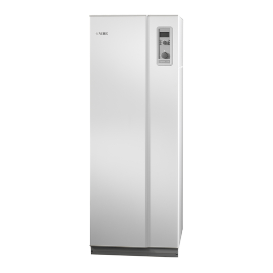
- Page 1 MOS GB 1204-2 INSTALLATION AND MAINTENANCE INSTRUCTIONS F1330 NIBE F1330 431187...
-
Page 3: Table Of Contents
7.0 Clock __________________________________________ 65 8.0 Other settings ___________________________________ 66 Docking 9.0 Service menus___________________________________ 67 General ____________________________________________ 14 Example F1330 docked with an oil boiler/pellet boiler and Miscellaneous water heater (floating condensing) _____________________ 14 Technical data Electrical connection Component placement _______________________________ 69... -
Page 4: Off
General In order to get the ultimate benefit from your heat pump F1330 you should read through this Installation and Maintenance Instruction. F1330 is a heat pump for heating large properties such as apartment buildings and industrial properties. Soil, rock or lakes can be used as heat source. -
Page 5: User Guide
F1330 has integrated circulation pumps (except The brine emits its heat to the refrigerant in the heat 60 kW which has an external brine pump) making it easy pump’s evaporator. -
Page 6: Front Panel
Menu 1.0 is then dis- operational. played. The screen saver comes on automatically 30 minutes after the last button was pressed and Oil boiler symbol when starting the heat pump. Indicates that the oil boiler is activated. NIBE F1330... -
Page 7: Switch
2.0 is shown on the display and the value for the Summer mode: calculated flow temperature changes. Only hot water production using F1330. The circu- Note! Only the knob on the Master unit can be lation pumps and additional heating are blocked. -
Page 8: Room Temperature Automatic Heating Control System
One to three lines approximately represents a 1 degree change in room temperature. NOTE! An increase in the room temperature may be in- hibited by the radiator or floor heating thermostats, if so these must be turned up. NIBE F1330... -
Page 9: Setting The Heating Controls Setting Using Diagrams
Setting the heating controls Setting the heating controls Setting using diagrams Offset heating curve -2 The heating control system of the F1330 is controlled by HEATING CURVE the outside temperature. This means the flow temperature VÄRMEKURVA is regulated in relation to the current outdoor temperature. - Page 10 User guide NIBE F1330...
-
Page 11: Installation / Adjustment
3 x 450 - 4 x 450 m 3 x 150 - 5 x 150 m The F1330 must be installed on a firm surface, preferably a concrete floor or a concrete foundation in a boiler room 4 x 500 - 6 x 500 m 4 x 170 - 5 x 200 m or a separate equipment room. -
Page 12: Removing The Covers
Installation / Adjustment General information for the installer Removing the covers NIBE F1330... -
Page 13: Pipe Connections General
Pipe installation must be carried out in accordance with Compression ring or press coupling should current norms and directives. F1330 can work up to a be used. return temperature of approx. 58 °C and an outgoing temperature from the heat pump of approx. -
Page 14: Pressure Expansion Vessel
22 - 30kW F1330-22/30/40 F1330-60 40kW Flow Flow 1,2 l/s 0,00 0,20 0,40 0,60 0,80 1,00 1,20 1,40 1,60 1,80 Available pressure, collector side (ethanol 28 %) Pressure Pressure 22 - 30kW F1330-22/30/40 F1330-60 40kW Flow Flow 3,5 l/s NIBE F1330... -
Page 15: Filling And Venting The Collector System
The valve on the main pipe between service connec- tions is closed. To fill, start the pump in the filling vessel and allow it to F1330 22-40 kW run until the fluid comes back in the return hose. The fluid can circulate via the mixing vessel until fluid, without air, returns to the return hose. -
Page 16: Docking General
More docking options can be found at http://www.nibe.eu Example F1330 docked with an oil boiler/pellet boiler and water heater (floating condensing) Oil-fired boiler or electric boiler Oljepanna alternativt elpanna with shunt med shunt SÄV... -
Page 17: Electrical Connection Electrical Installation
(see the fig- ure). The breaker is reset by twisting the control knob to horizontal position. NOTE! Reset the miniature circuit-breaker and the motor cut-out. They may have tripped during transportation. NIBE F1330... -
Page 18: Connection
NOTE! It is not permitted to fit additional compo- separate one nents in the electrical connection area. The F1330 does not include an isolator switch on the Note that F1330 provides 230V control signals that incoming electrical supply. The installation must be pre-... -
Page 19: Description Of Functions - Start Up Inspection
3. Set in the Service position from menu 8.1.1. (See the example in Control > Changing parameters.) +Measure card 4. On delivery F1330 is set with English as the menu language, if another language is required this can be changed in the menu 8.1.2. -
Page 20: Start Up With A F1330
When all heat pumps have undergone this inspection, continue with “Description of functions” - “Start up” > “Start up with a F1330” or if several F1330 are connected “Description of functions” - “Start up” > “Start up with several F1330s in a system”... -
Page 21: Start Up With Several F1330S In A System
Start up with several F1330s in a system Operating type selection 1. F1330 is delivered as the Master. Other units in the sys- The operating type must be selected for each connected tem must be selected as unique slaves. This is done ac- F1330. -
Page 22: Master / Slave
Description of functions - Start up Master / Slave F1330 is always delivered as the Master. Up to 8 Slaves can be connected to the Master. Only one heat pump with each address can be installed in the same system, i. e. only one Master and only one Slave 5. -
Page 23: Description Of Functions - Basic Functions
10 days cont: Continuous operation for 10 days. The pump then switches to intermittent operation. The heat pump in the picture is fitted with accessories. The factory setting is Intermittent. The outline diagram with docking instructions is available at www.nibe.eu NIBE F1330... -
Page 24: Heating Medium Pumps (Vbp-A/Vbp-B And Vbp3)
Economy and Continuous operation are only recom- Spring/Autumn mode: mended when there is no external circulation pump. Only production of heating and hot water using F1330. Menu 6.1.1 Op-mode external cp The circulation pumps are operational. Additional heat The operating mode for an external heating medium blocked. - Page 25 RCU offset. 0.2 A) on the relay card. Menu 2.3 Min. flow temp. Note that F1330 delivers 230 V control signals intend- ed to control external contactors and not to drive The set minimum level for the flow temperature to the pumps.
-
Page 26: Hot Water
1.8. That’s to say, if compressor 1 starts at 50 °C and stops at 55 °C then compressor 2 starts at 49.5 °C and stops at 54.5 °C i.e. each F1330 connected for possible switching between hot water and heating has its own shuttle valve. -
Page 27: Extra Hot Water
+EBV-card The heat pump in the picture is fitted with accessories. The outline diagram with docking instructions is available at www.nibe.eu Quick guide - menu settings ”Extra hot water” additional heat shall stop during hot water production is set here. The value is adjustable between 50 and 80 °C, Extra hot water or ”Off”. -
Page 28: Electrical Additional Heater
ETS-2 is connected to terminal blocks X6:15 (N) and X6:16 (230 V with activation). F1330 delivers 230 V control signals for additional heat, i. e. signals to control external relays, contactors etcetera, ETS-3 is connected to terminal blocks X6:12 (N) and X6:13 however, not to power these. - Page 29 230 V 230 V 230 V 230 V 230 V 230 V 230 V 230 V 230 V 230 V 230 V 230 V 230 V 230 V The outline diagram with docking instructions is available at www.nibe.eu NIBE F1330...
-
Page 30: Oil Boiler
In standby mode the output ETS-3/OP (Base card) is volt- age fed and with that, F1330 requests the oil boiler. However, the boiler shunt (SV-P) must be controlled manu- ally in standby mode. -
Page 31: Gas Boiler
-12 °C. Outgoing functions > Oil boiler to connect it as an oil boiler. brine from the F1330 is connected directly to the air mod- ule. When the outdoor air temperature is lower than the... -
Page 32: Hpac
F1330 automatically switches to cooling mode when the outdoor temperature exceeds the set value in menu 6.4.5. Passive cooling means that F1330, with the help of the cir- culation pumps, circulates fluid from the soil/rock collector in the house’s distribution system and cools the house. - Page 33 1 and 9 °C. The factory setting is 4 °C.9 °C. Outdoor temperature (menu 4.0) at the outdoor sensor (UG) when the heat pump switches to heating mode. The value is adjustable between 0 and 30 °C. The factory setting is 20 °C. NIBE F1330...
-
Page 34: Fixed Condensing
flow line sensor (FG) during period 2 when Own pro- gram is selected in menu 9.2.1. The value is adjustable The outline diagram with docking instructions is between 15 and 50 °C. The factory setting is 35 °C. available at www.nibe.eu NIBE F1330... -
Page 35: Room Control
9.1.11. The value can be adjusted between 10 and 30 °C Even the menu 3.5 (External adjustment 2) comes into in increments of 0.5 °C. Factory setting is 20 °C. question if the Sub shunt (SV-V2) has been activated. NIBE F1330... -
Page 36: Description Of Functions - Expansion Card 11
To connect HPAC on Expansion card 11 see the section Description of functions - Basic functions > Electrical Description of functions - Basic functions > HPAC. additional heater. The heat pump in the picture is fitted with accessories. NIBE F1330... -
Page 37: Hot Water Circulation Pump
Here the period time for the hot water circulation pump is set here. Adjustable between 10 and 60 minutes. The factory setting is 15 minutes. The outline diagram with docking instructions is The heat pump in the picture is fitted with accessories. available at www.nibe.eu NIBE F1330... -
Page 38: Pool
5 minute intervals until no more are available or the number of started compressors is the same as the number that is selected in menu 6.5.5. The heat pump in the picture is fitted with accessories. NIBE F1330... - Page 39 6.5.3) is to be used to heat the house when there is a need of heating and pool heating. The value is adjustable between 0 and 1000 minutes. The factory setting is 50 minutes. The outline diagram with docking instructions is available at www.nibe.eu NIBE F1330...
-
Page 40: Sub Shunt
The shunt valve (SV-V2) is connected to the terminal blocks X6A:5 (230 V decrease signal), X6A:6 (N) and X6A:7 (230 V increase signal). Note that F1330 delivers 230 V control signals intend- ed to control external contactors and not to drive pumps. - Page 41 The value is adjustable between 10 and 65 °C. The factory setting is 15 °C. The outline diagram with docking instructions is available at www.nibe.eu NIBE F1330...
-
Page 42: Description Of Functions - Expansion Card 12
When it has been connected the card must be activated in menu 9.1.2. Docking instructions Outline diagrams with docking instructions for the functions on the expansion card 12 is at the address www.nibe.eu The heat pump in the picture is fitted with accessories. NIBE F1330... -
Page 43: Groundwater Pump
Groundwater pump There is a potential free relay for the ground water pump A ground water pump (CP-G) can be controlled by F1330. function (CP-G), which can be used as control voltage or The pump starts 20 seconds before the first compres- power supply (Max 6 A, 250 V). -
Page 44: Passive Cooling With 4 Pipe System
If a submerged tube is not available, use the copper tube supplied. The sensor is connected to screw terminals J5:7 and J5:8 on the “measurement card”. +Measure card +Exp. card 12 The heat pump in the picture is fitted with accessories. NIBE F1330... - Page 45 Outdoor temperature (menu 4.0) at the outdoor sensor (UG) when the heat pump is permitted to produce heat. The value can be set between 0 and 30 °C. The factory setting is 20 °C. The outline diagram with docking instructions is available at www.nibe.eu NIBE F1330...
-
Page 46: Passive Cooling With 2 Pipe System
(CP-K) is connected to terminal block X6B:22 (max fusing 6 A and 250 V) and the control signal/ power supply is on X6B:23. +Exp. card 2 The heat pump in the picture is fitted with accessories. NIBE F1330... - Page 47 Outdoor temperature (menu 4.0) at the outdoor sensor (UG) when the heat pump is permitted to produce cool- ing. The value can be set between 0 and 30 °C. he factory setting is 25 °C. The outline diagram with docking instructions is available at www.nibe.eu NIBE F1330...
-
Page 48: Combined Cooling/Heating Modes With Accumulators
Cooling dump sensor J4:21-22 Brine out external J4:23-24 Block passive cooling J5:3-4 Block active cooling J5:5-6 Cooling flow line J5:7-8 The outline diagram with docking instructions is The heat pump in the picture is fitted with accessories. available at www.nibe.eu NIBE F1330... - Page 49 No.between 1 and 10. The factory setting is 1. is adjustable between -10 and +10. Default values: 0. Menu 6.7.9 Min. calc flow temp. The lowest cooling flow temperature in cooling mode is set here. The value is adjustable between 0 and 30°C. Default values: 25°C. NIBE F1330...
-
Page 50: Description Of Functions - External Control Electrical Connection, External Control/Blocking Of The Additional Heat And Compressor
0.2.x, the compressor A will start with an open input and Connection is made to terminals X4:3 and X4:4 on the stop when the input is made. However, alarms and time EBV-card (2). conditions in F1330 are superordinate to the external con- trol. Tariff A (TA) +EBV-card Input (TA) can be used to select additional heat type (oil or electricity) if additional heat in menu 9.1.8 is selected... -
Page 51: Control Control
A key lock can be activated in the main menus by simulta- neously pressing the plus and the minus buttons. The key symbol will then be shown on the display. The same proce- dure is used to deactivate the key lock. NIBE F1330... -
Page 52: Changing Parameters
Press the plus or minus button several times to move to menu 1.0 Normal menus: Displayed in all menu modes. Extended menus: Only displayed when extended or service is selected in menu 8.1.1. Service menus: Only dispalyed when service is selected in menu 8.1.1 NIBE F1330... -
Page 53: Menu Tree
Periodtime HW/Heat. Medium outdoor temp. [N] Maxtime HW-product. [U] Return to 4.0 Diff between compr. HW with additional Start temp. additional 1.9.0 heat [U] 1.9.1 heat Stop temp. additional 1.9.2 heat 1.9.3 Return to 1.9.0 1.10 Return to 1.0 NIBE F1330... - Page 54 Ctrl.valve intensific. Normal menus: Displayed in all menu modes. 6.6.4 Zero Extended menus: Only displayed when extended or 6.6.5 Return to 6.6.0 service is selected in menu 8.1.1. Service menus: Only dispalyed when service is selected in menu 8.1.1 NIBE F1330...
- Page 55 Room sensor [N] 6.9.1 Room balancing 8.3.6 Ratio of transf. EBV 6.9.2 Room balancingsystem [U] 8.3.7 Tariff status 6.9.3 Desired room temp 8.3.8 Return to 8.3.0 6.9.4 Return to 6.9.0 Return to 8.0 6.10 Return to 6.0 * Accessories NIBE F1330...
-
Page 56: Rcu
Normal menus: Displayed in all menu modes. 9.4.5 Return to 9.4.0 Extended menus: Only displayed when extended or Return to 9.0 service is selected in menu 8.1.1. Service menus: Only dispalyed when service is selected in menu 8.1.1 NIBE F1330... -
Page 57: Main Menus
8.1.1. via the outdoor sensor (UG). Values can be read and various settings can be made from these sub-menus. NOTE! These settings should only be made by persons with the necessary exper- tise. * Accessories NIBE F1330... -
Page 58: 0.0 System
(HW), radiator heating (Rad), pool heating (Pool) or shown, this means the high pressure pressostat has tripped cooling (Cold) are shown here. during hot water charging and F1330 has automatically Menu 0.1.1 Status Master A lowered the set temperature with the value in brackets. -
Page 59: 2.0 Flow Temperature
Extended menus: Only displayed when extended or heating engages. The value is adjustable between 5 and 60 service is selected in menu 8.1.1. °C. The factory setting is 45 °C. Service menus: Only displayed when service is selected in menu 8.1.1. NIBE F1330... -
Page 60: Flow Temperature 2
1 and 10. The factory setting is 1. Extended menus: Only displayed when extended or service is selected in menu 8.1.1. Menu 3.10 Return Service menus: Only displayed when service is selected Pressing the Enter button returns you to menu 3.0. in menu 8.1.1. NIBE F1330... -
Page 61: 4.0 Outdoor Temperature
Menu 5.4.3 Max. brine in Menu 5.2.8 Return Maximum permitted brine temperature in to the heat Pressing the enter button returns you to menu 5.2.0. pump. Can be set between -10 and +40 °C or Off. The factory setting is Off. NIBE F1330... - Page 62 Menu 5.4.4 Level monitor Menu 5.4.11 Reset alarm Select here if an external brine pressostat, level sensor or Resetting/acknowledging an alarm on F1330. flow sensor is connected to the “EBV card”. Menu 5.4.12 Pool heating compr. A Can be set to On (NC), On (NO) or Off. The factory setting The menu is only displayed when pool is selected as “On”...
-
Page 63: 6.0 External Units
Pressing the enter button takes you to sub- menus where settings concerning the connected electri- cal additional heater for heat production are made. Only shown when Electricity or Electri/Oil is selected in menu 9.1.8. NIBE F1330... - Page 64 If the flow temperature on the sensor (FG) exceeds the cal- culated flow temperature + this value the system switches to active cooling. The value is adjustable between 1 and 9 °C. The factory setting is 4 ° C. NIBE F1330...
- Page 65 8.1.1. Menu 6.7.17 Periodtime heatdump Service menus: Only displayed when service is selected The time period for the shunt (SV-VD) is chosen here. The in menu 8.1.1. value is adjustable between: 1 and 500. Default values: 30. NIBE F1330...
- Page 66 8.1.1. The selected cooling curve offset is shown here. The value Service menus: Only displayed when service is selected can be set between -10 and +10. The factory setting is 0. in menu 8.1.1. NIBE F1330...
-
Page 67: 7.0 Clock
Pressing the enter button returns you to menu 8.1.0. Changes to the flow temperature with a day change, e.g. the night reduction is set here. The value is adjustable be- tween -10 and +10. The factory setting is 0. NIBE F1330... -
Page 68: 9.0 Service Menus
Extended menus: Only displayed when extended or service is selected in menu 8.1.1. The setting (16, 20, 25, 35, 50 or 63 A) selected on the EBV-card (2) knob (100) is shown here. Service menus: Only displayed when service is selected in menu 8.1.1. NIBE F1330... - Page 69 The value is adjustable from 0 to 20 (UG) when the alarm tripped. days. The factory setting is 0. Menu 9.3.x.6 Hot watertemperature Shows the hot water temperature on sensor (VVG) when the alarm tripped. NIBE F1330...
- Page 70 Pressing the enter button returns you to menu 9.3.0. Normal menus: displayed in all menu modes. Extended menus: Only displayed when extended or service is selected in menu 8.1.1. Service menus: Only displayed when service is selected in menu 8.1.1. NIBE F1330...
-
Page 71: Technical Data
Control Technical data Component placement 22 - 40 kW F1330-22, 30, 40 F1330-22 F1330-30, 40 The heat pump in the picture is fitted with accessories. NIBE F1330... - Page 72 Miscellaneous Technical data Component placement 60 kW F1330-60 The heat pump in the picture is fitted with accessories.c NIBE F1330...
-
Page 73: List Of Components
Heating medium flow from module B Return line from water heater Air vent valve, heating medium system Drain for heating medium system Venting valve, collector system Drain for collector system Temperature sensor, brine out, (KB-utB) Temperature sensor, brine out, (KB-utA) NIBE F1330... -
Page 74: Dimensions And Setting-Out Coordinates
Cable gland, sensors electrical sensors electrical supply supply 1530 1530 1160 1160 Pipe connections ext ø 22 – 40 kW 60 kW (4)/(5) Brine in/out (mm) (70)/(72) Heating medium out/supply (mm) (Cooling module A/B) (71)/(73) Heating medium return (mm) NIBE F1330... -
Page 75: Technical Data
Tubes for sensors sors with probes Thermal insulating tape Outside sensor 3 x current transformers 2 x Hoses Safety valve (3 bar), Brine pump with flanges, (not 60kW) heating medium flow ø35 collector side gaskets and attachment (only 60kW) NIBE F1330... -
Page 76: Accessories
Part no. 069 320 Part no. 069 321 Part no. 067 025 EP 42 EP 26 Electric element 15 kW Electric boiler 26 kW Electric boiler 42 kW Outdoor air collector Adapted for controlling from F1330 Only for NIBE F1330-60kW NIBE F1330... -
Page 77: Actions With Operating Disturbances
Low room temperature NOTE! Cause: Compressor and electric element do not heat up. As F1330 can be connected to a large Action: Check and replace the any blown circuit and main number of external units even these should fuses. -
Page 78: Alarm
The temperature of the outgoing heating medium (VBFA or VBFB) is outside the compressor’s working range. This may be due to: Incorrect flow. Incorrect settings The alarm is reset when the temperature drops 2 degrees on the return line. NIBE F1330... -
Page 79: Constant Alarm
1.2. Too high return temperature set in menu 5.4.1. The alarm is reset once the fault has been rectified and the unit has been restarted or the alarm has been acknowl- edged in menu 5.4.11 (Reset alarm). NIBE F1330... -
Page 80: Draining, Heating Medium Side
Screw in the venting screw. Start F1330 and check whether the circulation pump runs. It is usually easier to start the circulation pump with F1330 running, switch (8) set to 1. If helping the circulation pump 16/19 to start is performed with F1330 running, be prepared for the screwdriver to jerk when the pump starts. - Page 81 Miscellaneous NIBE F1330...
- Page 82 Miscellaneous NIBE F1330...
- Page 83 Miscellaneous NIBE F1330...
- Page 84 Tel: +43 (0)7662 8963-0 Fax: +43 (0)7662 8963-44 E-mail: mail@knv.at www.knv.at NIBE Wärmetechnik AG, Winterthurerstrasse 710, CH-8247 Flurlingen Tel: (52) 647 00 30 Fax: (52) 647 00 31 E-mail: info@nibe.ch www.nibe.ch Druzstevni zavody Drazice s.r.o, Drazice 69, CZ - 294 71 Benatky nad Jizerou Tel: +420 326 373 801 Fax: +420 326 373 803 E-mail: nibe@nibe.cz www.nibe.cz...
Need help?
Do you have a question about the F1330 and is the answer not in the manual?
Questions and answers