Advertisement
Quick Links
Installation Instructions
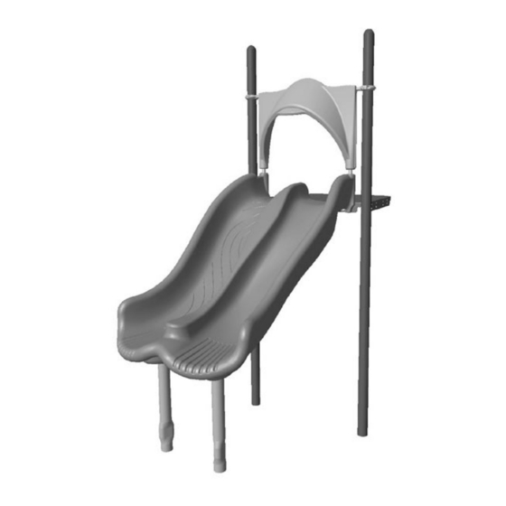
Assembly View
Page 1 of 8
Installation Instructions
Challengers
48 in. (1219 mm)
Twist and Shout Slide
Installation Preparation
Recommended Crew: ........................... Two (3) adults
Installation Time: ................................... 3 man-hours
Concrete Required: ............................... 0.06 cubic yard (0,05 cubic meters)
Use Zone: .............................................. Refer to Master Drawing
User Group Age (years): ....................... ASTM/CSA: 2-12, EN: 2-14
ICON KEY
Fully Tighten
Hardware
Do Not Fully Tighten
Hardware
Drill
Hammer
Model CH2727
®
Critical Fall Height
Pour Concrete
Dig Footing Holes
Model CH2727
ECN 1805 (ECN2805)
Advertisement

Related Manuals for Playworld Challengers CH2727


Summary of Contents for Playworld Challengers CH2727
- Page 1 Installation Instructions Installation Instructions Challengers Model CH2727 ® 48 in. (1219 mm) Twist and Shout Slide Installation Preparation Recommended Crew: ......Two (3) adults Installation Time: ........3 man-hours Concrete Required: ....... 0.06 cubic yard (0,05 cubic meters) Use Zone: ..........Refer to Master Drawing User Group Age (years): .......
-
Page 2: Installation Instructions
Installation Instructions Top View Footing Diagram 48" (1219 mm) 78.3" (1990 mm) 18" (457 mm) Diameter 64" (1626 mm) 13.5" 53.2" (343 mm) (1351 mm) 38" (965 mm) 21" 12" (533 mm) (305 mm) 48" Diameter (1219 mm) 11" Surfacing Level (279 mm) 48"... - Page 3 Component Footing Detail (ASTM/CSA) • The footings shown on Playworld Systems’ documentation are recommendations based on historical performance in average soil conditions. Footing dimensions may be modifi ed by the owner based on actual soil conditions. For example: - If local soil is loose or unstable, a larger footing may be required.
- Page 4 Installation Instructions Follow the details in alphabetical order. For clarifi cation, each detail references the step description. The step descriptions start on page 6. 3/8" x 1" Button Head Bolt BAE0664 3/8" x 3/4" 3/8" x 3/4" Button Head Bolt Button Head Bolt BAE0659 BAE0659...
- Page 5 Installation Instructions Canopy Canopy BPL2040 BPL2040 Slide BPL2038 3/8" x 1-3/4" 3/8" x 1" Button Head Bolt Set Screw BAE0665 BAE0629 Detail E Detail G Step 8 Step 10 Support Post Centerline Clamp Top Rail Support Post AAU0556 Drive Rivet BAE0020 3/8"...
- Page 6 Installation Instructions Assemble the canopy top rail. __Notes Before You Begin: Do not over tighten bolts during assembly, only snug __Step 7: Attach the clamps to the top rail. See Detail D. Select the top rail, and tighten them until assembly is complete. Do not install bolt caps until the structure the centerline clamps, and the appropriate hardware.
- Page 7 Installation Instructions Final Details. __Step 11: Plumb and level the component. Tighten all fasteners. Fully tighten all fasteners according to tightening torque specifi cations. In-ground: Block and brace for concrete. Pour concrete after all equipment has been assembled. Allow 72 hours for concrete to completely cure. Torque Specifi...
-
Page 8: Bill Of Materials
Bill of Materials Installation Instructions CH2727- 48 in (1219 mm) TWIST AND SHOUT SLIDE PART NO. DESCRIPTION QTY. AAU0556 CLAMP - 3-1/2" CENTERLINE DIE CAST AFM1855 FAB MTL. - 1.315" O.D. x 42-1/2" w/ 2 INSERTS & 4 HOLES 1 APT0216 POST - 3-1/2"...
Need help?
Do you have a question about the Challengers CH2727 and is the answer not in the manual?
Questions and answers