Advertisement
Quick Links
Installation Instructions
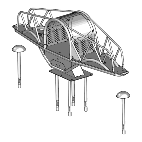
Assembly View
A
A
Page 1 of 20
(representative model)
Rocking/Springing Equipment
Intended for Standing Use Zones
A =
ASTM: 84 in. (2134 mm)
CSA: 2100 mm
EN: 1500 mm
Installation Instructions
Playworld Systems
Models XX0182 and XX0182S
Unity Teeter Tunnel
Installation Preparation
Recommended Crew: ........................... Four (4) adults
Installation Time: ................................... 12 man-hours (In-Ground)
Installation Time: ................................... 9 man-hours (Surface Mount)
Concrete Required (In-Ground): ........... 0.78 cubic yard (0,60 cubic meters)
Use Zone: .............................................. Refer to the information below
User Group Age (years): ....................... ASTM/CSA: 5-12, EN: 6-14
ICON KEY
Fully Tighten
Hardware
Do Not Fully Tighten
Hardware
Drill
Hammer
®
Add 1 Drop of
Thread Locking Adhesive
Pour Concrete
Dig Footing Holes
Critical Fall Height
Models XX0182 and XX0182S
ECN2664
Advertisement

Related Manuals for Playworld Unity Teeter Tunnel XX0182


Summary of Contents for Playworld Unity Teeter Tunnel XX0182
- Page 1 Installation Instructions Installation Instructions Playworld Systems ® Models XX0182 and XX0182S Unity Teeter Tunnel Installation Preparation Recommended Crew: ......Four (4) adults Installation Time: ........12 man-hours (In-Ground) Installation Time: ........9 man-hours (Surface Mount) Concrete Required (In-Ground): ... 0.78 cubic yard (0,60 cubic meters) Use Zone: ..........
-
Page 2: Top View
Installation Instructions Position Unit of Measurement Top # Inches Bottom # [Millimeters] Top View Footing Diagram 34" (864 mm) Elevation Views XX0182 Page 2 of 20 Models XX0182 and XX0182S ECN2664... - Page 3 Installation Instructions Position Unit of Measurement Top # Inches Bottom # [Millimeters] Top View Footing Diagram 34" (864 mm) Elevation Views XX0182S Page 3 of 20 Models XX0182 and XX0182S ECN2664...
-
Page 4: Installation Instructions
(457 mm) (Drill holes in cap to allow Diameter • The footings shown on Playworld Systems’ documentation are recommendations based for water drainage) on historical performance in average soil conditions. Footing dimensions may be modifi ed Support Post Footing Detail (ASTM/CSA) by the owner based on actual soil conditions. - Page 5 Installation Instructions FOOTING NOTES Surface Mount Post • All support posts and component support legs may have either a factory-applied sticker with line, or factory-applied mark designating protective surfacing level on a clear and Protective level installation site. Surfacing Level •...
- Page 6 Installation Instructions Follow the details in alphabetical order. For clarifi cation, each detail references the step description. The step descriptions start on page 16. Pivot Base AFR1606 1/2" x 1-1/2" (1 Total) Button Head Bolt BAE0687 (6 Total) 1/2" Flat Washer Anchor Frame BAE0690 AFR1559...
- Page 7 Installation Instructions Tie Rod AFM7999 (1 Total) Pivot Base 3" Bumper AMC0114 Bushing (4 Total) AMC0115 (2 Total) Detail C Step 6 Assemble the pivot base. Page 7 of 20 Models XX0182 and XX0182S ECN2664...
- Page 8 Installation Instructions See-Saw Base Frame AFR1985 (1 Total) 3/8" x 1" Button Head Bolt BAE0664 (2 Total) Middle connection Pivot Frame AFR1986 (2 Total) 1/2" Hex Lock Nut BAE0720 1/2" x 1.25" (8 Total) Button Head Bolt BAE9066 (8 Total) 1/2"...
- Page 9 Installation Instructions Platform Center Panel BFC6072 (1 Total) Platform Bumper AAU6153 (2 Total) Platform End Panel BFC6071 (2 Total) 3/8" Button Head Nut BAE0663 (14 Total) 3/8" Flat Washer BAE0595 (8 Total) 1" O.D. Flat Washer BAE0600 (14 Total) 3/8" x 3/4" 3/8"...
- Page 10 Installation Instructions Handrail Side Frame AFR1984 (1 Total) Handrail Side Frame AFR1984 (1 Total) 1/2" Flat Washer BAE0690 (8 Total) 1/2" x 2.50" Hex Head Bolt BAE9067 (8 Total) Bottom connections Detail G Step 10 Attach the handrail side frames to the bottom of the see-saw base frame. Page 10 of 20 Models XX0182 and XX0182S ECN2664...
- Page 11 Installation Instructions 3/8" x 1.25" Barrel Nut BAE0632 (4 Total) 3/8" x 1-1/2" Button Head Bolt BAE06645 (4 Total) Top connections (Center section) 3/8" x 1.25" Barrel Nut BAE0632 (4 Total) 3/8" x 3/4" Button Head Bolt BAE0659 (4 Total) Top connections (End sections) Detail H...
- Page 12 Installation Instructions Edge Bumper AAU6152 (2 Total) 1/4" x 1-1/4" Button Head Bolt BAE01525 (4 Total) 1/4" Button Head Nut BAE0161 (4 Total) Detail J Step 12 Attach the edge bumpers to the platform end panels. Page 12 of 20 Models XX0182 and XX0182S ECN2664...
- Page 13 Installation Instructions Window Frame BPM0363 (1 Total) 3/8" Flat Washer BAE0595 (20 Total) 3/8" x 1" Button Head Bolt BAE0664 (10 Total) Note: The window frame is shown transparent for ease of 3/8" Thin Series Lock Nut viewing the connection. BAE0610 (10 Total) Plastic Washer...
- Page 14 Installation Instructions Lexan Window BFC6073 (1 Total) Plastic Washer 3/8" Thin Series Lock Nut (half of a two-piece assembly) BAE0610 BPL0300 (14 Total) (14 Total) 3/8" Flat Washer BAE0595 (28 Total) 3/8" x 1" Button Head Bolt BAE0664 (14 Total) Detail L Step 14 Attach the lexan window to the window frame.
- Page 15 Installation Instructions Plastic Bolt Cap (half of a two-piece assembly) BPL0300 (24 Total) Detail M Step 16 Press the plastic bolt cap into the plastic washer.. Page 15 of 20 Models XX0182 and XX0182S ECN2664...
- Page 16 Installation Instructions Notes Before You Begin: Do not over tighten bolts during assembly, only snug Step 9: Attach the platform panels to see-saw frame. See Detail F. Place the tighten them until assembly is complete. Do not install bolt caps until the structure panels on the frame and attach as shown.
- Page 17 Step 17: For areas complying with ASTM standard F1487 or the CSA Z-614, apply the age appropriate label to the component at eye level. For Customer Service, Call 800-233-8404 or 570-522-9800 OUTSIDE U.S. 1000 Buffalo Road • Lewisburg, PA 17837 www.playworld.com Page 17 of 20 Models XX0182 and XX0182S ECN2664...
-
Page 18: Bill Of Materials
Bill of Materials Installation Instructions XX0182 - UNITY TEETER TUNNEL XX0182S - UNITY TEETER TUNNEL SURFACE MOUNT PART NO. DESCRIPTION QTY. PART NO. DESCRIPTION QTY. AAU6152 BUMPER - PLATFORM EDGE AAU6152 BUMPER - PLATFORM EDGE AAU6153 BUMPER - 7.00" DIA INSERT AAU6153 BUMPER - 7.00"... - Page 19 Minor burrs or sharp edges • Contact your sales representative or call Playworld may be removed by using a sharp utility knife or block Systems’ Customer Service for a replacement part.
- Page 20 Inspection Form Installation Instructions Preventive Maintenance • Be sure that you are using a copy of this Inspection Form and not your original..for Safety's Sake! • Use the Inspection Codes listed below and record condition of equipment at time of examination on the Inspection Checklist.
- Page 21 • Insure that Age Appropriate and Hard Surface Warning/Playworld Systems • Good drainage around the structure and its supports is important. Inquire identifi cation labels are properly affi xed to the play equipment. Labels are to be with local contractors for appropriate recommendations.
- Page 22 • IMPORTANT! Because accidental falls around your playground equipment Maintenance can occur, Playworld Systems recommends that the area under and around the • Inadequate maintenance of equipment has resulted in injuries on the structure be covered with a resilient material such as sand, bark mulch, or wood playground.
- Page 23 FINAL INSPECTION • Insure that hard surface warning/Playworld Systems identifi cation labels are • Playworld Systems ® insists on the installation of protective surfacing within the ® properly affi xed to the play equipment. Labels are to be plainly visible according use zone of each play structure in accordance with the applicable standard or to current playground equipment guidelines.
Need help?
Do you have a question about the Unity Teeter Tunnel XX0182 and is the answer not in the manual?
Questions and answers