
Related Manuals for Banner ABR 7000 Series


Summary of Contents for Banner ABR 7000 Series
- Page 1 ABR 7000 Series Barcode Reader Instruction Manual Original Instructions 207634 Rev. A 28 January 2019 © Banner Engineering Corp. All rights reserved 207634...
-
Page 2: Table Of Contents
ABR 7000 Series Barcode Reader Contents 1 Product Description ................................4 1.1 Models ......................................4 1.2 Laser Description and Safety Information ............................4 1.3 Features ......................................5 1.3.1 Indicators ....................................6 1.3.2 Diagnostic Indication ................................6 1.3.3 Button ......................................6 2 Specifications and Requirements ...........................7... - Page 3 ABR 7000 Series Barcode Reader 8.1 Industrial Ethernet Setup in Barcode Manager ..........................59 8.1.1 Set the Industrial Ethernet Protocol (EtherNet/IP, Modbus/TCP) ..................59 8.1.2 Industrial Ethernet Reading Phase Control ........................... 59 8.1.3 Industrial Ethernet Reading Phase Acquisition Control ......................61 8.1.4 Industrial Ethernet Digital Output Control...
-
Page 4: Product Description
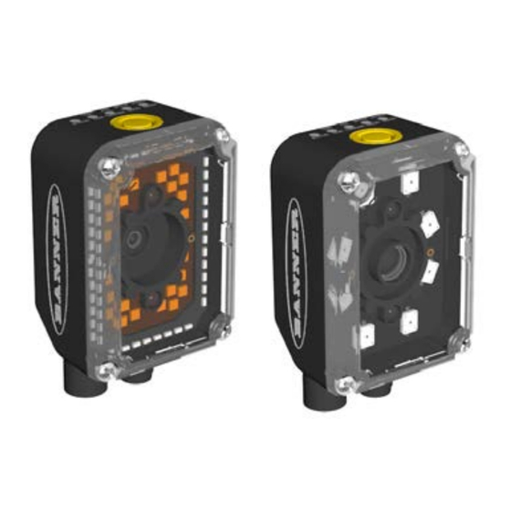
ABR 7000 Series Barcode Reader 1 Product Description Imager-based barcode reader with superior decoding capability and a powerful array of lens and lighting options • Powerful decoding capability to read even difficult 1D and 2D codes • Superior ability to read DPM and low contrast codes •... -
Page 5: Features
ABR 7000 Series Barcode Reader CAUTION: Use of controls or adjustments or performance of procedures other than those specified herein may result in hazardous radiation exposure. Do not attempt to disassemble this sensor for repair. A defective unit must be returned to the manufacturer. -
Page 6: Indicators
ABR 7000 Series Barcode Reader 1.3.1 Indicators Indicator Color Description Power Blue Indicates that the reader is connected to the power supply Ethernet Amber Indicates connection to the Ethernet network Connection STATUS No read result COM/Test Amber Active result output transmission on the Main serial port Figure 3. -
Page 7: Specifications And Requirements
FCC Statement Modifications or changes to this equipment without the expressed written approval of Banner Engineering could void the authority to use the equipment. This device complies with PART 15 of the FCC Rules. Operation is subject to the following two conditions: (1) This device may not cause harmful interference, and (2) this device must accept any interference received, including interference which may cause undesired operation. -
Page 8: Specifications-Software
ABR 7000 Series Barcode Reader 2.2 Specifications—Software Operating Mode Continuous, One Shot, Phase Mode Configuration Methods Smart Teach Human Machine Interface ABR 7000: Windows-based SW (Barcode Manager) via Ethernet Interface Host Mode Programming sequences sent over Serial or Ethernet TCP interfaces... - Page 9 ABR 7000 Series Barcode Reader 20.5 [0.81] [2.13] [1.42] M4 #4 Optical Axis Connector block rotates to 90° position Figure 5. Overall Dimensions with Connector at 0° 20.5 [0.81] [2.12] [1.69] [1.42] M4 #4 Optical Axis Figure 6. Overall Dimensions with Connector at 90°...
-
Page 10: Installation Instructions
ABR 7000 Series Barcode Reader 3 Installation Instructions 3.1 Handling Proper handling ensures that the ABR will function correctly. The ABR is designed for use in an industrial environment. It is built to withstand vibration and shock when correctly installed. However, it is also a precision product and before and during installation it must be handled properly to avoid damage. -
Page 11: Position The Reader
ABR 7000 Series Barcode Reader 3.3 Position the Reader The ABR is able to decode code labels at a variety of angles; however significant angular distortion may degrade reading performance. When mounting the ABR, consider these ideal label position angles: Pitch or Skew 10° to 20° and Tilt 0°. The reader can read a code at any tilt angle provided the code fits into the Field Of View (FOV). -
Page 12: Focus Lock Label-Optional
ABR 7000 Series Barcode Reader 3.4 Focus Lock Label—Optional The Focus Lock Label is for ABR 7000 manual focus models only. There are five single-use focus lock labels included in the packaging that can be used to protect the focus position from being changed after the application has been completed. -
Page 13: Serial Connection
ABR 7000 Series Barcode Reader Power TCNM-ACBB1 Host Switch 1. Ethernet Interface 2. Main Serial Interface (Data Monitor) 3. External Trigger (for One Shot or Phase Mode) Figure 12. Ethernet Network Layout 3.5.2 Serial Connection In this layout the data is transmitted to the Host on the main serial interface. The Ethernet interface can be used for reader configuration by connecting a laptop computer running Barcode Manager. -
Page 14: Id-Net Multidata Network (Pass-Through)
ABR 7000 Series Barcode Reader Alone Alone Alone Phase Continuous Mode Mode External Trigger Power TCNM-ACBB1 Host 1. Ethernet TCP/IP Server 1 Switch 2. Ethernet TCP/IP Server 2 3. Main Serial Interface (RS232 or RS422 Full-Duplex) 4. -
Page 15: Id-Net Synchronized Network
ABR 7000 Series Barcode Reader Alone Alone Alone ID-NET ID-NET ID-NET Master Slave #1 Slave #2 Phase Continuous Mode Mode External Trigger TCNM-ACBB1 Host STP-M12D-4xx Switch 1. Ethernet TCP/IP Server 1 2. ID-NET (up to 32 devices, max network extension of 1000 m) 3. -
Page 16: Connector Descriptions
ABR 7000 Series Barcode Reader ID-NET ID-NET Synchronized Synchronized Slave #1 Slave #n TCNM-ACBB1 Power ID-NET Synchronized Master Host 1. Main Serial Interface (RS232 or RS422 Full-Duplex) 2. External Trigger 3. ID-NET (up to 16 devices - practical limit) Figure 16. - Page 17 ABR 7000 Series Barcode Reader Figure 18. M12/Euro-style 17-pin male Communications, I/O, and Power Connector Table 2: Power and I/O Pinouts for MQDC2S-17xx Wire Color Description Brown Power Supply Input Voltage + Blue Power Supply Input Voltage - White Input Signal 2 B (polarity insensitive)
-
Page 18: Inputs
ABR 7000 Series Barcode Reader • Connect pin "Earth" of the TCNM-ACBB1 connection box to a good earth ground • For direct connections, connect the cable shield to the locking ring nut of the connector 3.6.2 Inputs There are two opto-isolated polarity insensitive inputs available on the M12 17-pin connector of the reader: Input 1 (External Trigger) and Input 2, a generic input. -
Page 19: Wiring
ABR 7000 Series Barcode Reader 3.6.4 Wiring ABR7000 10-30V dc – Load Output 1 * Load Output 2 * – BN – BU Load Output 3 * – WH – GN Trigger A (polarity insensitive) – PK – YE Trigger B (polarity insensitive) –... -
Page 20: Ethernet Connector
ABR 7000 Series Barcode Reader ABR7000 10-30V dc – Load Output 1 * Load Output 2 * – BN – BU Load Output 3 * – WH – GN Trigger A (polarity insensitive) – PK – YE Trigger B (polarity insensitive) –... -
Page 21: Ethernet Interface
ABR 7000 Series Barcode Reader Name Function TX + Transmitted data (+) RX + Received data (+) TX - Transmitted data (-) RX - Received data (-) 3.6.6 Ethernet Interface The Ethernet interface can be used for TCP/IP communication with a remote or local host computer by connecting the reader to either a LAN or directly to a host PC. -
Page 22: Power Supply
ABR 7000 Series Barcode Reader TCNM-ACBB1 Terminal Block Connectors Outputs Power Source - Outputs Power Reference - Outputs Output 1 + opto-isolated and polarity sensitive Output 1 - opto-isolated and polarity sensitive Output 2 + opto-isolated and polarity sensitive Output 2 - opto-isolated and polarity sensitive... -
Page 23: User Interface-Serial Host
ABR 7000 Series Barcode Reader RS232 Interface The RS232 interface is generally used for Point-to-Point connections. When it is connected to the host computer it allows transmission of code data. The following pins are used for RS232 interface connection: TCNM-ACBB1... -
Page 24: Id-Net Interface
ABR 7000 Series Barcode Reader 3.7.4 ID-NET Interface TCNM-ACBB1 Function Shield Network Cable Shield ID-NET network + ID-NET network - Network Reference ID-NET Cables The following instructions refer to the figures in ID-NET Network Termination on page 25. • The general cable type specifications are: CAT5 twisted pair + additional CAT5 twisted pair, shielded cable AWG 24... - Page 25 ABR 7000 Series Barcode Reader Max ID-NET Response Time 14 15 Number of Nodes 500 kbps 250 kbps 125 kbps Figure 22. ID-NET Response Time CONDITIONS • ID-NET M/S Synchronized layout • message length = 50 bytes per node ID-NET Network Termination The network must be properly terminated by a 120 Ohm resistor at the first and last reader of the network.
- Page 26 ABR 7000 Series Barcode Reader TCNM-ACBB1 HOST RS232/RS422 Reader Master External Power for ABR and I/O Accessories TCNM-ACBB1 Reader Slave External Power for ABR and I/O Accessories TCNM-ACBB1 Reader Slave (up to 31) External Power for ABR and I/O Accessories Figure 23.
- Page 27 ABR 7000 Series Barcode Reader TCNM-ACBB1 HOST RS232/RS422 Reader Master TCNM-ACBB1 Reader Slave TCNM-ACBB1 Reader Slave (up to 31) Power Source (12-24 Vdc) Figure 24. ID-NET Network Connections with Common Power Branch Network www.bannerengineering.com - Tel: + 1 888 373 6767...
-
Page 28: Auxiliary Rs232 Interface
ABR 7000 Series Barcode Reader TCNM-ACBB1 HOST RS232/RS422 Reader Master TCNM-ACBB1 Reader Slave TCNM-ACBB1 Reader Slave (up to 31) Power Source (12-24 Vdc) Figure 25. ID-NET Network Connections with Common Power Star Network 3.7.5 Auxiliary RS232 Interface The RS232 auxiliary interface is available for Point-to-Point connections. When it is connected to the host computer it allows transmission of code data. -
Page 29: Inputs
ABR 7000 Series Barcode Reader TCNM-ACBB1 Function Auxiliary Interface Receive Data Auxiliary Interface Transmit Data SGND Auxiliary Interface Reference USER INTERFACE RX TX Reference Figure 27. RS232 Auxiliary Interface Connections Note: Do not connect the Auxiliary Interface to the TCNM-ACBB1 spring clamp connectors and the 9-pin connector simultaneously. - Page 30 ABR 7000 Series Barcode Reader TCNM-ACBB1 Function Power Source - External Trigger External Trigger A (polarity insensitive) External Trigger B (polarity insensitive) Power Reference - External Trigger The yellow Trigger LED is on when the active state of the External Trigger corresponds to ON.
- Page 31 ABR 7000 Series Barcode Reader Jumper NPN Photoelectric Sensor Figure 29. NPN External Trigger Using ABR Power External Trigger Input Connections Using External Power PNP Photoelectric Sensor Input Signal Pulled down to External Input Device Reference Figure 30. PNP External Trigger Using External Power...
- Page 32 ABR 7000 Series Barcode Reader NPN Photoelectric Sensor Pulled up to External Input Device Power Input Signal Figure 31. NPN External Trigger Using External Power TCNM-ACBB1 Function Power Source - Inputs Input 2 A (polarity insensitive) Input 2 B (polarity insensitive)
-
Page 33: Outputs
ABR 7000 Series Barcode Reader Input 2 Connections Using External Power Input Device Input Signal Pulled down to External Input Device Reference Figure 34. PNP Input 2 Using External Power Input Device Pulled up to External Input Device Power Input Signal Figure 35. - Page 34 ABR 7000 Series Barcode Reader Power Dissipation: 90mW maximum at 50 °C (122 °F) ambient temperature By default, Output 1 is associated with the No Read event, which activates when the code(s) signaled by the external trigger are not decoded. Output 2 is associated with the Good Read event, which activates when all the selected codes are correctly decoded.
- Page 35 ABR 7000 Series Barcode Reader Output 1 Device Output 2 Device Output Output Signal Signal Pulled down to External Pulled down to External Output Device Reference Output Device Reference Figure 39. NPN/Open Collector Output Using External Power Output 3 is not opto-isolated but can be assigned to the same events. By default it is not assigned to any event.
-
Page 36: Smart Teach Interface
ABR 7000 Series Barcode Reader 4 Smart Teach Interface Smart Teach is designed to improve ease of installation and maintenance Status information is clearly presented by means of the five colored LEDs. The single push button provides access to the following modes. -
Page 37: Aim-Manual Focus Models
ABR 7000 Series Barcode Reader 3. To exit the test, press the Smart Teach button once. Note: By default, the Test exits automatically after three minutes. 4.2 Aim—Manual Focus Models The Aim function turns on the built-in laser pointer aiming system to aid reader positioning. Because the laser pointers are centered on the FOV, use them to position the imager on the code. -
Page 38: Setup
ABR 7000 Series Barcode Reader 5. Within 3 seconds (before the reader flashes), position the code closest to your application code size at the center of the Field of View (equidistant from the laser pointers). The code must not move during this procedure. -
Page 39: Getting Started
3. Run Barcode Manager_Setup.exe to access the installation screen. 4. Follow the onscreen installation procedure. After the installation is complete, the Barcode Manager entry is created under Start > Programs > Banner Engineering. A desktop icon is also created. 5.2 Ethernet Device Discovery The following configuration procedure assumes that a laptop computer running Barcode Manager is connected to a factory default reader through the Ethernet port. - Page 40 ABR 7000 Series Barcode Reader 1. Confirm the network connections. Changing the Local Area Connection (LAN) properties of the programming computer to be compatible with the ABR device on the network may be required for connection. a) Click the Start button, then on the Start menu, click Control Panel or search for Control Panel.
-
Page 41: Serial Device Discovery
ABR 7000 Series Barcode Reader 5.3 Serial Device Discovery Note: Although this feature allows all devices to be configured through their Serial Interface, be aware that transmission speeds and some Barcode Manager features are limited when using this interface. It is advised to use the Ethernet interface whenever possible. -
Page 42: Device Configuration
ABR 7000 Series Barcode Reader 6 Device Configuration 6.1 Automatic Setup To begin configuration, the reader must be correctly mounted at the correct reading distance for your application so that its Field of View covers the application reading area. Advanced Setup for Manual Adjustable Focus Models Note: For Manual Adjustable Focus models go to on page 46. -
Page 43: Advanced Setup For Liquid Lens Autofocus Models
ABR 7000 Series Barcode Reader 6. Click Start Automatic Setup. The Automatic Setup window opens. Figure 52. Automatic Setup 7. Select the correct reading conditions. • Static Tuning—No maximum limit on exposure time • Dynamic Tuning—Maximum allowable image exposure is automatically calculated using the parameters •... - Page 44 ABR 7000 Series Barcode Reader 6. After the chart is positioned, click Pause to stop image acquisition. Figure 53. Chart Positioned 7. Click Image Settings. 8. Click Image Auto Setup to automatically acquire the best exposure time and gain values.
- Page 45 ABR 7000 Series Barcode Reader 12. Click Focus Autolearn. Tip: You may have to click Image Settings again before you can click Focus Autolearn. Note: The Reading Distance value is not significant until the Focus Autolearn procedure ends successfully. The Calibrate dialog box opens allowing you to start the procedure.
-
Page 46: Advanced Setup For Manual Adjustable Focus Models
ABR 7000 Series Barcode Reader 16. Click the Data Matrix ECC 200 symbology under the Image Settings branch (enabled by default). If this symbology is among those in your application it will be shown in the image display with its code symbology name and a small green box around it indicating it is decoded. - Page 47 ABR 7000 Series Barcode Reader 3. Click Advanced Setup. 4. Click the Play icon. PPI (Pixels Per Inch) Setup Chart 5. Place the PPI (Pixels per Inch) Setup Chart in the reading area. See on page 120. 6. After the chart is positioned, click the Pause icon to stop image acquisition.
- Page 48 ABR 7000 Series Barcode Reader 12. From the main menu open Options > UI Settings > Configuration tab. 13. Select Focus Calibration under View Window if it is not already selected. Figure 59. UI Settings www.bannerengineering.com - Tel: + 1 888 373 6767...
- Page 49 ABR 7000 Series Barcode Reader 14. Click the Focus Calibration tab at the bottom of the window. Note: This feature is only available for manual focus models. The oscilloscope view is shown in the bottom panel and can be used for manual focus adjustment.
-
Page 50: Reading Phase
ABR 7000 Series Barcode Reader 15. Click Acquire PPI to automatically set the Image Density so that the ABR functions correctly and to the fullest extent of its capabilities. This procedure is necessary to enable transmitting accurate barcode size estimates for barcodes at the same reading distance as the test card. -
Page 51: Good Read Setup
ABR 7000 Series Barcode Reader 2. Select your application-specific Operating Mode from the icons over the Configuration Parameters tree area: • Continuous • One Shot • Phase Mode Continuous Mode and Acquisition Trigger are shown by default. 3. Configure the relative Operating Mode parameters from the Reading Phase parameters panel. -
Page 52: Data Formatting
ABR 7000 Series Barcode Reader 3. If a Good Read condition should be produced when any single code is decoded, independent from the others, combine them in logical XOR. a) Drag the code icon(s) from their relative Expected Code box into the Expected Code box of the XOR combination you wish to create. - Page 53 ABR 7000 Series Barcode Reader 2. Configure your application-specific Data Formatting Message(s) from the Configuration Parameters tree area: Message 1, Message 2, etc. Figure 66. Data Formatting 3. Add fields to the output message by clicking on the icons above the Message Field area.
-
Page 54: Output Setup
ABR 7000 Series Barcode Reader 6.7 Output Setup 1. Configure your application-specific Digital Output(s) and Green/Red Spots (if used) from the Configuration Parameters tree area: Output 1, Output 2, etc. Figure 67. Output Setup 2. Save the configuration from temporary memory to permanent memory, overwriting the previously saved configuration. -
Page 55: Over-Exposure
ABR 7000 Series Barcode Reader Figure 68. Example Under Exposure: Too Dark 6.8.2 Over-Exposure To correct an over-exposure result, change the following parameters in order: 1. Decrease the Gain. 2. Decrease the Exposure Time. www.bannerengineering.com - Tel: + 1 888 373 6767... -
Page 56: Code Moving Out Of The Fov
ABR 7000 Series Barcode Reader Figure 69. Example Over Exposure: Too Light 6.8.3 Code Moving Out of the FOV To correct code moving out of the FOV and have the code completely visible in FOV, follow one or both of the following options: •... - Page 57 ABR 7000 Series Barcode Reader Figure 70. Example of Code out of the FOV Figure 71. Add Delay on Trigger to Correct Out of FOV www.bannerengineering.com - Tel: + 1 888 373 6767...
-
Page 58: Advanced Reader Configuration
ABR 7000 Series Barcode Reader 7 Advanced Reader Configuration For further details on advanced product configuration, refer to the Barcode Manager Instruction Manual available in the Barcode Manager Help menu. 7.1 Host Mode Programming The reader can also be remotely configured from a host system using the Host Mode programming command language. -
Page 59: Industrial Ethernet Overview
ABR 7000 Series Barcode Reader 8 Industrial Ethernet Overview The ABR reader can be monitored and controlled using Industrial Ethernet protocols (EtherNet/IP or Modbus/TCP). On the monitoring side, the ABR makes the barcode data output string configured on the Data Formatting page available to a PLC or HMI along with eight user-defined output bits. - Page 60 ABR 7000 Series Barcode Reader 1. Go to Reading Phase > Phase Mode > Phase On and select an input bit from the Industrial Protocol Input Bit list. In this example, select Bit 2. Industrial Ethernet Bits Figure 72. Industrial Ethernet Input Bits Configured for Phase On Control 2.
-
Page 61: Industrial Ethernet Reading Phase Acquisition Control
ABR 7000 Series Barcode Reader 8.1.3 Industrial Ethernet Reading Phase Acquisition Control To acquire individual images using an Industrial Protocol Input Bit, use the following instructions: 1. Go to Reading Phase > Phase Mode > Acquisition Trigger and select Trigger Type as External. -
Page 62: Digital Input Echo To Industrial Ethernet
ABR 7000 Series Barcode Reader 3. Under Deactivation, select the same bit and set it to Trailing. When the host turns on the ABR Input Bit, the ABR turns on its physical discrete Output 1. Industrial Ethernet Bits Figure 75. Industrial Ethernet Strings and Bits 8.1.5 Digital Input Echo to Industrial Ethernet... -
Page 63: Transmitting Output Data Messages Using Industrial Ethernet
ABR 7000 Series Barcode Reader 3. Under Deactivation, select the same input and set the polarity to Trailing. When physical Input 1 turns on, the Industrial Ethernet host controller will see the ABR Output Bit 0 turn on. Input 1 echo to Industrial... -
Page 64: Ethernet/Ip
ABR 7000 Series Barcode Reader 3. Click on the relevant Industrial Protocol. In this example, Message 2 has been linked to the EtherNet/IP Industrial Protocol. The data from Message 2 will be sent, as an ASCII string, to the ABR Industrial Protocol output data registers. Arrows should be drawn automatically from the messages to the Industrial Ethernet channel in the diagram in the center of the screen. - Page 65 ABR 7000 Series Barcode Reader Last Item Sequence Number The Last Item Sequence Number is written with the Item Sequence Number by the Originator (PLC) to acknowledge the receipt of the Item Data. If fragmentation is used, this value is not written until the complete message is received.
- Page 66 ABR 7000 Series Barcode Reader Item Data Size The Item Data Size is the total size of the Item Data. If the Item Data Size is greater than 128 characters, fragmentation is Example of Message Transmissions in Action used (see the fragmentation example in on page 66).
-
Page 67: Configuring The Abr For Ethernet/Ip In Barcode Manager
ABR 7000 Series Barcode Reader To ABR from PLC To PLC from ABR Last Last Item Item Fragment Fragment Fragment Fragment Sequence Sequence Sequence Item Size Description Sequence Size Data Buffer Number Number Number Number [128–255] ABR sends fragment 2 of item 2 PLC acknowledges fragment 2 [256–383]... -
Page 68: Abr Series Eds File Installation In Studio 5000 Logix Designer Software
ABR 7000 Series Barcode Reader • Discard After Read—After the last code in the output buffer is read by the EtherNet/IP server manager (host), it is deleted from the output buffer. In this way it will not be re-read by the same host (or any host) in case of a re- connection. - Page 69 ABR 7000 Series Barcode Reader 5. Browse to locate the EDS file and click Next. Figure 81. Select File to Register 6. Click Next to register the tested file. Figure 82. Register the Tested File www.bannerengineering.com - Tel: + 1 888 373 6767...
- Page 70 ABR 7000 Series Barcode Reader 7. Click Next when you see the icon associated with the EDS file. Figure 83. Rockwell Automation's EDS Wizard 8. Click Next to register the EDS file. Figure 84. Register the EDS File 9. Click Finish to close the EDS Wizard .
- Page 71 ABR 7000 Series Barcode Reader 10. Right-click on the PLC's Ethernet adapter and select New Module... Figure 85. New Module 11. Locate the ABR from the catalog and click Create. Figure 86. Select Module Type 12. Enter a name, description (optional), and IP address for the ABR.
- Page 72 ABR 7000 Series Barcode Reader 13. Set the desired Request Packet Interval (RPI) on the Connection tab. Figure 88. New Module—Connection Settings www.bannerengineering.com - Tel: + 1 888 373 6767...
-
Page 73: Abr Series Manual Installation In Studio 5000 Logix Designer Software
ABR 7000 Series Barcode Reader 8.2.4 ABR Series Manual Installation in Studio 5000 Logix Designer Software If the EDS file installation in the previous section is not possible, follow the steps of this section. Otherwise skip this section. 1. Add a generic Ethernet module to the PLC's Ethernet card. -
Page 74: Abr Series Aoi Installation In Logix Designer Software
ABR 7000 Series Barcode Reader 3. Click OK. 4. Set the desired Request Packet Interval (RPI) value and click OK. Figure 92. Module Properties Report: Ethernet 8.2.5 ABR Series AOI Installation in Logix Designer Software 1. Download the Add-On Instruction (AOI) file Banner_ABR_AOI_IO_Data_1_0.L5X from www.bannerengineering.com... - Page 75 ABR 7000 Series Barcode Reader 4. Click Open. The Import Configuration window opens. The default selection creates all of the necessary items for the AOI. Figure 95. Import Configuration 5. Click OK to complete the import process. The AOI is added to the Controller Organizer window and looks similar to the following figure: Figure 96.
- Page 76 ABR 7000 Series Barcode Reader 7. For each of the questions marks, create and link a new tag array. The AOI includes a new type of User Defined Tag (UDT), a custom array of tags meant specifically for this AOI.
-
Page 77: Aoi Data Description
ABR 7000 Series Barcode Reader 9. Verify that the Banner ABR Ethernet Module is connected by making sure that there is not a yellow warning symbol over the module icon in the Controller Organizer. If there is no symbol, the ABR has a live connection to the PLC. -
Page 78: Modbus/Tcp
ABR 7000 Series Barcode Reader FailureCode The Failure Code is set when an error occurs with the reader. The following is a table of Failure Codes: Failure Code Name 0×01 Input Failure 0×02 Communications Failure 0×04 Reader Failure 0×08 Software Error 0×10... -
Page 79: Abr Output Message Data
ABR 7000 Series Barcode Reader 02: Read Input Status Register ABR Input Bit Position 10006 Input Bit 5 10007 Input Bit 6 10008 Input Bit 7 Table 5: ABR Output Bits (00001–00008) 05: Write Single Coil Register ABR Output Bit Position... - Page 80 ABR 7000 Series Barcode Reader Figure 103. Modbus/TCP-Specific Settings and Their Default Values Start Register Defines the offset added to the Starting Address field of the Modbus/TCP message. If set to 5, the output messages are written from 40006 to 40025 instead of from 40001 to 40020.
-
Page 81: Reading Features
ABR 7000 Series Barcode Reader 9 Reading Features 9.1 FOV Calculation Figure 1 Use the data in the following table to calculate the FOV for your application. Refer to and the formula below. Table 7: 7000 Models Model Lens Type... -
Page 82: Global Fov Diagrams
ABR 7000 Series Barcode Reader 9.2 Global FOV Diagrams Note: The following diagrams are given for typical performance at 25° C using high quality grade A symbols according to ISO/IEC 15416 (1D code) and ISO/IEC 15415 (2D code) print quality test specifications. -
Page 83: Liquid Lens Autofocus Models 9 Mm Lens
ABR 7000 Series Barcode Reader 2D Codes Distance Figure 106. 2D Codes 9.2.2 Liquid Lens Autofocus Models 9 mm Lens 1D Codes Distance Figure 107. 1D Codes www.bannerengineering.com - Tel: + 1 888 373 6767... -
Page 84: Manual Focus Models 9 Mm Lens
ABR 7000 Series Barcode Reader 2D Codes Distance Figure 108. 2D Codes 9.2.3 Manual Focus Models 9 mm Lens 1D Codes Distance Figure 109. 1D Codes www.bannerengineering.com - Tel: + 1 888 373 6767... -
Page 85: Manual Focus Models 12 Mm Lens
ABR 7000 Series Barcode Reader 2D Codes Distance Figure 110. 2D Codes 9.2.4 Manual Focus Models 12 mm Lens 1D Codes Distance Figure 111. 1D Codes www.bannerengineering.com - Tel: + 1 888 373 6767... -
Page 86: Manual Focus Models 16 Mm Lens
ABR 7000 Series Barcode Reader 2D Codes Distance Figure 112. 2D Codes 9.2.5 Manual Focus Models 16 mm Lens 1D Codes Distance Figure 113. 1D Codes www.bannerengineering.com - Tel: + 1 888 373 6767... -
Page 87: Reading Diagrams
ABR 7000 Series Barcode Reader 2D Codes Distance Figure 114. 2D Codes 9.3 Reading Diagrams • The following reading diagrams are references and are provided for typical performance at 25 °C using high quality grade A symbols: Code 128 (1D code) and Data Matrix ECC 200 (2D code). -
Page 88: Abr7106-Xxe2 (6 Mm Models) 1D Codes
ABR 7000 Series Barcode Reader 9.3.1 ABR7106-xxE2 (6 mm models) 1D Codes Code 128 0.12 mm (5 mils) Focusing Distance 70 mm -1.5 Reading Distance Figure 115. Code 128 0.12 mm (5 mils) Hardware Settings Code Symbology Code 128 Code Resolution 0.12 mm (5 mils) - Page 89 ABR 7000 Series Barcode Reader Code 128 0.25 mm (10 mils) Focusing Distance 130 mm Reading Distance Figure 116. Code 128 0.25 mm (10 mils) Hardware Settings Code Symbology Code 128 Code Resolution 0.25 mm (10 mils) Tilt Angle 0°...
- Page 90 ABR 7000 Series Barcode Reader Code 128 0.30 mm (12 mils) Focusing Distance 160 mm Reading Distance Figure 117. Code 128 0.30 mm (12 mils) Hardware Settings Code Symbology Code 128 Code Resolution 0.30 mm (12 mils) Tilt Angle 0°...
- Page 91 ABR 7000 Series Barcode Reader Code 128 0.33 mm (13 mils) Focusing Distance 150 mm Focusing Distance 185 mm Reading Distance Figure 118. Code 128 0.33 mm (13 mils) Hardware Settings Code Symbology Code 128 Code Resolution 0.33 mm (13 mils) Tilt Angle 0°...
- Page 92 ABR 7000 Series Barcode Reader Code 128 0.38 mm (15 mils) Focusing Distance 200 mm Focusing Distance 220 mm Reading Distance Figure 119. Code 128 0.38 mm (15 mils) Hardware Settings Code Symbology Code 128 Code Resolution 0.38 mm (15 mils) Tilt Angle 0°...
- Page 93 ABR 7000 Series Barcode Reader Code 128 0.50 mm (20 mils) Focusing Distance 270 mm Focusing Distance 290 mm Reading Distance Figure 120. Code 128 0.50 mm (20 mils) Hardware Settings Code Symbology Code 128 Code Resolution 0.50 mm (20 mils) Tilt Angle 0°...
-
Page 94: Abr7106-Xxe2 (6 Mm Models) 2D Codes
ABR 7000 Series Barcode Reader 9.3.2 ABR7106-xxE2 (6 mm models) 2D Codes Data Matrix 0.19 mm (7.5 mils) Reading Max FOV Distance Focusing Distance 60 mm Horizontal Max FOV Reading Width +0.6 in +15 mm -0.6 in -15 mm Figure 122. Effective Field of View for High Resolution Codes with 6mm Lens Due to the "fisheye"... - Page 95 ABR 7000 Series Barcode Reader Data Matrix 0.25 mm (10 mils) Reading Max FOV Distance Focusing Distance 85 mm Horizontal Max FOV Reading Width +0.8 in +20 mm -0.8 in -20 mm Figure 124. Effective Field of View for High Resolution Codes with 6mm Lens Due to the "fisheye"...
- Page 96 ABR 7000 Series Barcode Reader Data Matrix 0.38 mm (15 mils) Focusing Distance 90 mm Reading Distance Figure 125. Focusing Distance—Data Matrix 0.38 mm (15 mils) Hardware Settings Code Symbology Data Matrix ECC 200 Code Resolution 0.38 mm (15 mils) Tilt Angle 45°...
-
Page 97: Abr7109-Xxe2 (9 Mm Models, Manual Focus) 1D Codes
ABR 7000 Series Barcode Reader 9.3.3 ABR7109-xxE2 (9 mm models, manual focus) 1D Codes Code 128 0.25 mm (10 mils) Reading Distance Figure 126. Code 128 0.25 mm (10 mils) Hardware Settings Code Symbology Code 128 Code Resolution 0.25 mm (10 mils) Tilt Angle 45°... - Page 98 ABR 7000 Series Barcode Reader Code 128 0.30 mm (12 mils) Reading Distance Figure 127. Code 128 0.30 mm (12 mils) Hardware Settings Code Symbology Code 128 Code Resolution 0.30 mm (12 mils) Tilt Angle 45° Skew Angle 15° Focusing Distance (mm)
- Page 99 ABR 7000 Series Barcode Reader Code 128 0.38 mm (15 mils) Reading Distance Figure 128. Code 128 0.38 mm (15 mils) Hardware Settings Code Symbology Code 128 Code Resolution 0.38 mm (15 mils) Tilt Angle 45° Skew Angle 15° Focusing Distance (mm)
-
Page 100: Abr7109-Xxe2 (9 Mm Models, Manual Focus) 2D Codes
ABR 7000 Series Barcode Reader 9.3.4 ABR7109-xxE2 (9 mm models, manual focus) 2D Codes Data Matrix 0.13 mm (5 mils) -0.5 -1.5 Reading Distance Figure 129. Data Matrix 0.13 mm (5 mils) Hardware Settings Code Symbology Data Matrix ECC 200 Code Resolution 0.13 mm (5 mils) - Page 101 ABR 7000 Series Barcode Reader Data Matrix 0.19 mm (7.5 mils) -0.5 -1.5 -2.5 Reading Distance Figure 130. Data Matrix 0.19 mm (7.5 mils) Hardware Settings Code Symbology Data Matrix ECC 200 Code Resolution 0.19 mm (7.5 mils) Tilt Angle 45°...
- Page 102 ABR 7000 Series Barcode Reader Data Matrix 0.25 mm (10 mils) Reading Distance Figure 131. Data Matrix 0.25 mm (10 mils) Hardware Settings Code Symbology Data Matrix ECC 200 Code Resolution 0.25 mm (10 mils) Tilt Angle 45° Skew Angle 15°...
-
Page 103: Abr7112-Rse2 (12 Mm Models) 1D Codes
ABR 7000 Series Barcode Reader 9.3.5 ABR7112-RSE2 (12 mm models) 1D Codes Code 128 0.25 mm (10 mils) Reading Distance Figure 132. Code 128 0.25 mm (10 mils) Hardware Settings Code Symbology Code 128 Code Resolution 0.25 mm (10 mils) Tilt Angle 45°... - Page 104 ABR 7000 Series Barcode Reader Code 128 0.30 mm (12 mils) Reading Distance Figure 133. Code 128 0.30 mm (12 mils) Hardware Settings Code Symbology Code 128 Code Resolution 0.30 mm (12 mils) Tilt Angle 45° Skew Angle 15° Focusing Distance (mm)
- Page 105 ABR 7000 Series Barcode Reader Code 128 0.38 mm (15 mils) Reading Distance Figure 134. Code 128 0.38 mm (15 mils) Hardware Settings Code Symbology Code 128 Code Resolution 0.38 mm (15 mils) Tilt Angle 45° Skew Angle 15° Focusing Distance (mm)
- Page 106 ABR 7000 Series Barcode Reader Code 128 0.50 mm (20 mils) Reading Distance Figure 135. Code 128 0.50 mm (20 mils) Hardware Settings Code Symbology Code 128 Code Resolution 0.50 mm (20 mils) Tilt Angle 45° Skew Angle 15° Focusing Distance (mm)
-
Page 107: Abr7112-Rse2 (12 Mm Models) 2D Codes
ABR 7000 Series Barcode Reader 9.3.6 ABR7112-RSE2 (12 mm models) 2D Codes Data Matrix 0.13 mm (5 mils) -0.5 -1.5 Reading Distance Figure 136. Data Matrix 0.13 mm (5 mils) Hardware Settings Code Symbology Data Matrix ECC 200 Code Resolution 0.13 mm (5 mils) - Page 108 ABR 7000 Series Barcode Reader Data Matrix 0.19 mm (7.5 mils) Reading Distance Figure 137. Data Matrix 0.19 mm (7.5 mils) Hardware Settings Code Symbology Data Matrix ECC 200 Code Resolution 0.19 mm (7.5 mils) Tilt Angle 45° Skew Angle 15°...
- Page 109 ABR 7000 Series Barcode Reader Data Matrix 0.25 mm (10 mils) Reading Distance Figure 138. Data Matrix 0.25 mm (10 mils) Hardware Settings Code Symbology Data Matrix ECC 200 Code Resolution 0.25 mm (10 mils) Tilt Angle 45° Skew Angle 15°...
- Page 110 ABR 7000 Series Barcode Reader Data Matrix 0.38 mm (15 mils) Reading Distance Figure 139. Data Matrix 0.38 mm (15 mils) Hardware Settings Code Symbology Data Matrix ECC 200 Code Resolution 0.38 mm (15 mils) Tilt Angle 45° Skew Angle 15°...
-
Page 111: Abr7116-Rse2 (16 Mm Models) 1D Codes
ABR 7000 Series Barcode Reader 9.3.7 ABR7116-RSE2 (16 mm models) 1D Codes Code 128 0.25 mm (10 mils) Reading Distance Hardware Settings Code Symbology Code 128 Code Resolution 0.25 mm (10 mils) Tilt Angle 45° Skew Angle 15° Focusing Distance (mm) - Page 112 ABR 7000 Series Barcode Reader Code 128 0.30 mm (12 mils) Reading Distance Hardware Settings Code Symbology Code 128 Code Resolution 0.30 mm (12 mils) Tilt Angle 45° Skew Angle 15° Focusing Distance (mm) Software Parameters Internal Lighting Very High Power Strobed ABR7116-RSE2 Exposure Time (μs)
- Page 113 ABR 7000 Series Barcode Reader Code 128 0.38 mm (15 mils) Reading Distance Hardware Settings Code Symbology Code 128 Code Resolution 0.38 mm (15 mils) Tilt Angle 45° Skew Angle 15° Focusing Distance (mm) Software Parameters Internal Lighting Very High Power Strobed ABR7116-RSE2 Exposure Time (μs)
- Page 114 ABR 7000 Series Barcode Reader Code 128 0.50 mm (20 mils) Reading Distance Hardware Settings Code Symbology Code 128 Code Resolution 0.50 mm (20 mils) Tilt Angle 45° Skew Angle 15° Focusing Distance (mm) Software Parameters Internal Lighting Very High Power Strobed ABR7116-RSE2 Exposure Time (μs)
-
Page 115: Abr7116-Rse2 (16 Mm Models) 2D Codes
ABR 7000 Series Barcode Reader 9.3.8 ABR7116-RSE2 (16 mm models) 2D Codes Data Matrix 0.19 mm (7.5 mils) 10.5 11.5 Reading Distance Hardware Settings Code Symbology Data Matrix ECC 200 Code Resolution 0.19 mm (7.5 mils) Tilt Angle 45° Skew Angle 15°... - Page 116 ABR 7000 Series Barcode Reader Data Matrix 0.25 mm (10 mils) Reading Distance Hardware Settings Code Symbology Data Matrix ECC 200 Code Resolution 0.25 mm (10 mils) Tilt Angle 45° Skew Angle 15° Focusing Distance (mm) Software Parameters Internal Lighting...
-
Page 117: Maximum Line Speed And Exposure Calculations
ABR 7000 Series Barcode Reader Data Matrix 0.38 mm (15 mils) Reading Distance Hardware Settings Code Symbology Data Matrix ECC 200 Code Resolution 0.38 mm (15 mils) Tilt Angle 45° Skew Angle 15° Focusing Distance (mm) Software Parameters Internal Lighting... - Page 118 ABR 7000 Series Barcode Reader In general, a longer time corresponds to a lighter image but is susceptible to blurring due to the code movement; a shorter exposure time corresponds to a darker image. Note: The following considerations must be applied only when the internal lighting system and 2D codes are used.
- Page 119 ABR 7000 Series Barcode Reader • Disabled: The built-in LED array is turned off all the time. This option can be useful if using an external lighting system. • Always ON: The built-in LED array is turned on all the time at the lowest power level. This option is useful if the LED- array blinking disturbs the operator (Strobed operating mode).
-
Page 120: Ppi (Pixels Per Inch) Setup Chart
ABR 7000 Series Barcode Reader 10 PPI (Pixels Per Inch) Setup Chart Print and use the Setup Chart on the following page to aid in aiming and focusing the reader (7000 models), the Advanced Setup of the reader (7000 models), and the Learn procedure (3000 and 7000 models). -
Page 121: Code 128
ABR 7000 Series Barcode Reader PPI (Pixels Per Inch) Setup Chart Code 128 Resolution mm (mils) 0.30 (12) 0.30 mm 0.50 (20) 0.50 mm 1.00 (40) 1 mm 15 cm 6 inch Do not use these Barcodes for Smart Teach Autolearn Do not scale this page www.bannerengineering.com - Tel: + 1 888 373 6767... -
Page 122: Application Examples
ABR 7000 Series Barcode Reader 11 Application Examples 11.1 Document Handling ABR is effective when used in the omnidirectional reading of 2D, stacked, linear, and postal codes. For example, in automated document handling and mail processing systems. Figure 148. Address Coded in Data Matrix Symbology for Automated Mail Processing 11.2 Deformed or Overprinted Code Reading... -
Page 123: Ink-Jet Printing Technology
ABR 7000 Series Barcode Reader Figure 152. Dot Matrix Code Directly Marked on Metal Surface by Using Dot Peening Technology Figure 153. Dot Peening Marking on Metal Surface with Multi-dot per Code Element Figure 154. Directly Marked Dot Matrix Code Characterized by Outstanding Separation Distance between Adjacent Code Elements 11.4 Ink-Jet Printing Technology... - Page 124 ABR 7000 Series Barcode Reader CAUTION: ABR readers are not designed to be used in real-time laser marking applications (Mark & Read). They must be mounted far away from the laser marker to avoid burning the CMOS sensor. www.bannerengineering.com - Tel: + 1 888 373 6767...
-
Page 125: Troubleshooting
• If you’re unable to fix the problem and you’re going to contact Banner Engineering, provide (if possible): Application Program version, Parameter Configuration file, serial number and model number of your reader. Most of this information is available while Barcode Manager is connected to the reader. - Page 126 ABR 7000 Series Barcode Reader Problem Solution Any Operating Mode: the Trigger LED is correctly blinking Check the Code Collection parameters on the Reading but no result is transmitted by the reader at the end of the Phase step and the Data Formatting parameters on the reading phase collection Data Formatting step.
-
Page 127: Lighting System Notes
ABR 7000 Series Barcode Reader 13 Lighting System Notes ABR 7000 Models Internal Illuminators Model Lens Type Number Color of LEDs ABR7106-RSE2 Red and Blue LEDs for bright/dark field lighting 6 mm Manual Focus Lens ABR7106-MSE2 24/39 in DPM applications (software configurable... - Page 128 ABR 7000 Series Barcode Reader Code Printing or Marking Technique Printing on paper or labels Figure 157. Examples Direct Marking with Ink Jet process Figure 158. Examples Direct Marking with Laser Etching process Figure 159. Examples Direct Marking with Dot Peening process Figure 160.
- Page 129 ABR 7000 Series Barcode Reader Shape of the code marking surface Flat surface Figure 161. Examples Curved surface Figure 162. Examples Reflectivity of the code marking surface Highly reflective surface Figure 163. Examples Opaque surface Figure 164. Examples www.bannerengineering.com - Tel: + 1 888 373 6767...
- Page 130 ABR 7000 Series Barcode Reader Texture of the code marking surface Smooth surface without any defects (such as scratches or streaks) Figure 165. Examples Surface with machining flaws produced by machining tools Figure 166. Examples Rough surface typical of die-cast parts Figure 167.
-
Page 131: Abr 7000 Recommended Illuminators
ABR 7000 Series Barcode Reader 13.2 ABR 7000 Recommended Illuminators In the following table, macro-cases are listed, and for each of them, the most suitable ABR 7000 lighting systems used to resolve the application. Application Characteristics Multicolored Multicolored DPM Central... -
Page 132: Red Illuminator
ABR 7000 Series Barcode Reader 13.2.1 Red Illuminator The red illuminator is made up of eight LEDs which are all controlled simultaneously by the software application. These are Bright Field general purpose illuminators used in the operating distance range from 20 mm to 550 mm. The reader focus distance further limits this range. - Page 133 ABR 7000 Series Barcode Reader Top-Left Sector Top-Right Sector Bottom-Right Sector Bottom-Left Sector Figure 171. Central LED Group Left Sector Top Sector Bottom Sector Right Sector Figure 172. Peripheral LED Group In the software, each single sector can be turned on, however it is NOT possible to simultaneously turn on sectors belonging to the separate LED Groups, Peripheral and Central.
-
Page 134: Abr 7000 Applications
ABR 7000 Series Barcode Reader Take into consideration that when using Multicolored DPM Central LED Group to illuminate surfaces where linear machining flaws are present, the well-lighted area depends on the direction of the machining flaws with respect to the illuminator's LED sectors, but independent of the reading distance. - Page 135 ABR 7000 Series Barcode Reader Figure 181. Multicolored DPM - Central Group: Figure 182. Multicolored DPM – Peripheral Figure 180. Red: Incorrect Illumination Incorrect Illumination Group: Good Illumination Highly Reflective Surfaces This example shows the benefits obtained with Multicolored DPM on codes produced using dot peening on metal surfaces with high reflectance.
- Page 136 ABR 7000 Series Barcode Reader Figure 189. Multicolored DPM - Peripheral Group Figure 190. Multicolored DPM - Peripheral Group Figure 188. Red: Incorrect Illumination ALL Sectors On: Incorrect Illumination Right Sector Off: Good Illumination Background with Anisotropic Reflectance Figure 191. Color Photo of Code Figure 192.
-
Page 137: Accessories
ABR 7000 Series Barcode Reader 14 Accessories 14.1 Brackets SMBABR7RA • Replacement right-angle bracket for ABR 7000 models • Included with the product 5X M4 #5 • 3 mm cold rolled steel 2X Ø8.2 3X Ø4.5 14.2 Cordsets 17-pin M12/Euro-style Female to DB25 Male Shielded... -
Page 138: Trigger Kit
ABR 7000 Series Barcode Reader 17-pin M12/Euro-style Extension Shielded Cable Model Length Style Dimensions Pinout (Female) MQDEC-1706SS 1.83 m (6 ft) MQDEC-1715SS 4.57 m (15 ft) 47 Typ. 11 = Gray/Pink 1 = Brown 12 =Red/Blue M12 x 1 - 6g... -
Page 139: Connection Boxes And Power Supply Boxes
ABR 7000 Series Barcode Reader 14.4 Connection Boxes and Power Supply Boxes TCNM-ACBB1 PSB4MK-24-06-Q0Q5 • Connection box • Power supply box • For ABR 3000 and 7000 • 0.6 A 24 V dc models • Requires AC cable SM30CC-306-WP •... -
Page 140: Product Support And Maintenance
15.1 Repairs Contact Banner Engineering for troubleshooting of this device. Do not attempt any repairs to this Banner device; it contains no field-replaceable parts or components. If the device, device part, or device component is determined to be defective by a Banner Applications Engineer, they will advise you of Banner's RMA (Return Merchandise Authorization) procedure. -
Page 141: Reset The Reader To The Factory Default Environment (Optional)
ABR 7000 Series Barcode Reader 3. Select the firmware package file for your device family. Figure 198. Select the Firmware File The Device Package Update window displays. 4. Click Yes to start the update. The Device Restart Information window displays. - Page 142 Park Lane, Culliganlaan 2F, bus 3 Email: mail@bannerengineering.com 1831 Diegem, Belgium Turkey Address: Phone: +90 216 688 8282 www.bannerengineering.com Banner Engineering Elk. San. Ve Tic. Ltd. Şti. Website: Şerifali Mah. Münevver Sok. Ekomed Plaza No:10 Kat:4 Email: turkey@bannerengineering.com.tr Ümraniye / İstanbul, Türkiye India Address: Phone: +91 (0) 206 640 5624 www.bannerengineering.com...
-
Page 143: Banner Engineering Corp. Limited Warranty
15.5 Banner Engineering Corp. Limited Warranty Banner Engineering Corp. warrants its products to be free from defects in material and workmanship for one year following the date of shipment. Banner Engineering Corp. will repair or replace, free of charge, any product of its manufacture which, at the time it is returned to the factory, is found to have been defective during the warranty period. This warranty does not cover damage or liability for misuse, abuse, or the improper application or installation of the Banner product. -
Page 144: Glossary
ABR 7000 Series Barcode Reader 16 Glossary AIM DPM Quality Guideline (Association for Automatic Identification and Standard applicable to the symbol quality Mobility): AIM Global is the international trade assessment of direct part marking (DPM) performed association representing automatic identification and in using two-dimensional barcode symbols. - Page 145 ABR 7000 Series Barcode Reader EEPROM Exposure Time Electrically Erasable Programmable Read-Only For digital cameras based on image sensors Memory. An on-board non-volatile memory chip. equipped with an electronic shutter, it defines the time during which the image will be exposed to the Element sensor to be acquired.
- Page 146 ABR 7000 Series Barcode Reader Random Access Memory. Data in RAM can be accessed in random order, and quickly written and read. Symbol Verification The act of processing a code to determine whether or not it meets specific requirements. Transmission Control Protocol/Internet Protocol...
- Page 147 Index EtherNet/IP 64–68, 73, 74, 77, 78 Modbus/TCP 78, 79 exposure 117 models 4 Add-On Instruction external trigger 30, 31 , See AOI advanced configuration 58 advanced setup output 54 adjustable focus 43 field of view output 1 34 manual adjustable focus 46 , See FOV output 2 34 aim 37...
Need help?
Do you have a question about the ABR 7000 Series and is the answer not in the manual?
Questions and answers