
Related Manuals for Daikin FVKS25BAVMB


Summary of Contents for Daikin FVKS25BAVMB
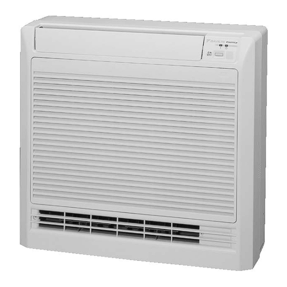
- Page 1 Si06-763 REMOVAL PROCEDURE S E R V I C E M A N U A L 2.5/3.5 kW Class Indoor Unit Inverter Floor Standing Type...
-
Page 2: Indoor Unit
Service Manual Removal Procedure Indoor Unit Cooling Only Heat Pump FVKS25BAVMB FVXS25BAVMB FVKS35BAVMB FVXS35BAVMB... -
Page 3: Table Of Contents
Si06-763 Table of Contents 1. Removal of the Air Filter / Front Panel ............2 2. Removal of the Horizontal Blade.............5 3. Removal of the Electrical Box ..............6 4. Removal of the PCB................9 5. Removal of the Heat Exchanger ............11 6. Removal of the Fan Rotor / Fan Motor..........13 Note: The illustrations may be slightly different depending on the model. -
Page 4: Removal Of The Air Filter / Front Panel
Removal of the Air Filter / Front Panel Si06-763 1. Removal of the Air Filter / Front Panel Procedure Warning Be sure to wait 10 minutes or more after turning off all power supplies before disassembling work. Step Procedure Points Appearance Operation panel Enlarged illustration... - Page 5 Si06-763 Removal of the Air Filter / Front Panel Step Procedure Points Press down the 2 hooks located at left and right side upper parts of the air filter, then bend slightly the air filter to remove it. (R2607) Unhook the chain. Chain (R2608) Removal Procedure...
- Page 6 Removal of the Air Filter / Front Panel Si06-763 Step Procedure Points Undo the 3 hooks on the bottom of the front panel. Hooks (three locations) (R2609) Loosen the 4 screws to Hooks take out the front grille. <Main unit side> (R2611) Mounting screw M4 ×...
-
Page 7: Removal Of The Horizontal Blade
Si06-763 Removal of the Horizontal Blade 2. Removal of the Horizontal Blade Procedure Warning Be sure to wait 10 minutes or more after turning off all power supplies before disassembling work. Step Procedure Points Open the horizontal blade. (R2612) Undo the supporting bracket at the center position. -
Page 8: Removal Of The Electrical Box
Removal of the Electrical Box Si06-763 3. Removal of the Electrical Box Procedure Warning Be sure to wait 10 minutes or more after turning off all power supplies before disassembling work. Step Procedure Points Set the horizontal blade in horizontal position to take out the front grille toward yourself. - Page 9 Si06-763 Removal of the Electrical Box Step Procedure Points Remove the room temperature thermistor. Room temperature thermistor (R2619) Thermistor Remove the heat retaining exchanger thermistor. spring Heat exchanger thermistor (R2621) Heat exchanger thermistor Be sure not to drop the thermistor retaining spring (R2620) Loosen the 2 screws to remove the drip proof...
- Page 10 Removal of the Electrical Box Si06-763 Step Procedure Points To remove the Mounting screw M4 × 16 electrical box, loosen the 2 fixing screws and pull out the box forward. (R2623) The figure shows parts in the electrical box. Indication lamps Green Yellow Red ON/OFF switch Signal...
-
Page 11: Removal Of The Pcb
Si06-763 Removal of the PCB 4. Removal of the PCB Procedure Warning Be sure to wait 10 minutes or more after turning off all power supplies before disassembling work. Step Procedure Points Loosen the fixing screw to remove PCBs from Power supply PCB the electrical box. - Page 12 Removal of the PCB Si06-763 Step Procedure Points The figure shows the power supply PCB (indoor unit). S202 SW2-1 : unused S204 SW2-2 : unused SW2-3 : unused SW2-4 : OFF - initial set ON - limit upward air flow (R2628) The figure shows the service PCB.
-
Page 13: Removal Of The Heat Exchanger
Si06-763 Removal of the Heat Exchanger 5. Removal of the Heat Exchanger Procedure Warning Be sure to wait 10 minutes or more after turning off all power supplies before disassembling work. Step Procedure Points Conduct pump-down Mounting screw M4 × 16 operation and check that gas has been purged completely before starting... - Page 14 Removal of the Heat Exchanger Si06-763 Step Procedure Points Loosen the fixing screw Mounting screw M4 × 16 to remove the pipe retaining plate of the Pipe retaining heat exchanger. plate Push the pipe retaining plate backward to undo the hook, then open the retaining plate using straight edge of screw- driver to remove the...
-
Page 15: Removal Of The Fan Rotor / Fan Motor
Si06-763 Removal of the Fan Rotor / Fan Motor 6. Removal of the Fan Rotor / Fan Motor Procedure Warning Be sure to wait 10 minutes or more after turning off all power supplies before disassembling work. Step Procedure Points For removal of the drain pan, disconnect the drain hose, then... - Page 16 Removal of the Fan Rotor / Fan Motor Si06-763 Step Procedure Points Loosen the 6 screws (3 Short lead wire: for the upper for the upper side fan motor motor and 3 for the Long lead wire: for the bottom one) to remove bottom fan motor the fan motors.
- Page 17 Revision History Month / Year Version Revised contents 07 / 2013 Si06-763 First edition...
- Page 18 Improper installation can result in water or refrigerant leakage, electrical shock, fire or explosion. Use only those parts and accessories supplied or specified by Daikin. Ask a qualified installer or contractor to install those parts and accessories. Use of unauthorised parts and accessories or improper installation of parts and accessories can result in water or refrigerant leakage, electrical shock, fire or explosion.
Need help?
Do you have a question about the FVKS25BAVMB and is the answer not in the manual?
Questions and answers