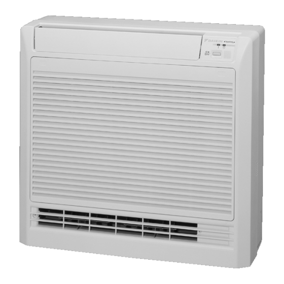
Daikin FVKS25BVMB Service Manual
Inverter pair floor standing type b series
Hide thumbs
Also See for FVKS25BVMB:
- Service manual (184 pages) ,
- Pocket manual (169 pages) ,
- Operation manual (32 pages)

Related Manuals for Daikin FVKS25BVMB


Summary of Contents for Daikin FVKS25BVMB
- Page 1 Si06-305 Service Manual Inverter Pair Floor Standing Type B Series [Applied Models] Inverter Pair : Cooling Only Inverter Pair : Heat Pump...
- Page 2 Inverter Pair Floor Standing Type Floor Standing Type Floor Standing Type Floor Standing Type B Series B Series B Series B Series Cooling Only Indoor Unit FVKS25BVMB FVKS35BVMB Outdoor Unit RKS25BVMB RKS35BVMB Heat Pump Indoor Unit FVXS25BVMB FVXS35BVMB Outdoor Unit RXS25BVMB...
-
Page 3: Table Of Contents
Si06-305 1. Introduction .....................v 1.1 Safety Cautions ..................v Part 1 List of Functions ..............1 1. Functions....................2 Part 2 Specifications ..............3 1. Specifications ..................4 1.1 Cooling Only.....................4 1.2 Heat Pump ....................5 Part 3 Printed Circuit Board Connector Wiring Diagram ..... 7 1. - Page 4 Si06-305 Part 5 System Configuration............43 1. System Configuration................44 1.1 Operation Instructions ................44 2. Instruction....................45 2.1 Safety Precautions .................45 2.2 Names of Parts..................47 2.3 Preparation before Operation..............50 2.4 AUTO·DRY·COOL·HEAT·FAN Operation ..........53 2.5 Adjusting the Air Flow Direction .............55 2.6 POWERFUL Operation ................57 2.7 Outdoor Unit Silent Operation ..............58 2.8 HOME LEAVE Operation ...............59 2.9 TIMER Operation ...................61...
- Page 5 Si06-305 Part 7 Removal Procedure ............113 1. Indoor Unit...................114 1.1 Removal of the Air Filter / Front Panel ..........114 1.2 Removal of the Horizontal Blade............117 1.3 Removal of the Electrical Box ..............118 1.4 Removal of the PCB................121 1.5 Removal of the Heat Exchanger ............123 1.6 Removal of the Fan Rotor / Fan Motor..........125 2.
-
Page 6: Introduction
Si06-305 Introduction 1. Introduction Safety Cautions Cautions and Be sure to read the following safety cautions before conducting repair work. The caution items are classified into “ Warning” and “ Caution”. The “ Warning” Warnings items are especially important since they can lead to death or serious injury if they are not followed closely. -
Page 7: Cautions Regarding Products After Repair
Introduction Si06-305 Caution Do not repair the electrical components with wet hands. Working on the equipment with wet hands can cause an electrical shock. Do not clean the air conditioner by splashing water. Washing the unit with water can cause an electrical shock. Be sure to provide the grounding when repairing the equipment in a humid or wet place, to avoid electrical shocks. -
Page 8: Inspection After Repair
Si06-305 Introduction Warning Be sure to use an exclusive power circuit for the equipment, and follow the technical standards related to the electrical equipment, the internal wiring regulations and the instruction manual for installation when conducting electrical work. Insufficient power circuit capacity and improper electrical work can cause an electrical shock or fire. -
Page 9: Using Icons
Introduction Si06-305 Warning Do not use a joined power cable or extension cable, or share the same power outlet with other electrical appliances, since it can cause an electrical shock, excessive heat generation or fire. Caution Check to see if the parts and wires are mounted and connected properly, and if the connections at the soldered or crimped terminals are secure. -
Page 10: Part 1 List Of Functions
Si06-305 Part 1 Part 1 Part 1 Part 1 List of Functions List of Functions List of Functions List of Functions 1. Functions....................2 List of Functions... -
Page 11: Functions
Functions Si06-305 Functions Category Functions Category Functions Inverter (with Inverter Power Control) Air Purifying Filter with Bacteriostatic, Virustatic Functions –10 –10 Operation Limit for Cooling (°C) Basic –15 Function Operation Limit for Heating (°C) — Photocatalytic Deodorizing Filter Air Purifying Filter with PAM Control Photocatalytic Deodorizing —... -
Page 12: Part 2 Specifications
Si06-305 Part 2 Part 2 Part 2 Part 2 Specifications Specifications Specifications Specifications 1. Specifications ..................4 1.1 Cooling Only.....................4 1.2 Heat Pump ....................5 Specifications... -
Page 13: Specifications
Specifications Si06-305 Specifications Cooling Only 230V, 50Hz Indoor Units FVKS25BVMB FVKS35BVMB Model Outdoor Units RKS25BVMB RKS35BVMB 2.5 (1.0~3.0) 3.5 (1.0~3.7) Capacity Btu/h 8,550 (3,400~10,250) 11,950 (3,400~12,600) Rated (Min.~Max.) kcal/h 2,150 (860~2,580) 3,010 (860~3,180) Moisture Removal Running Current (Rated) Power Consumption Rated... -
Page 14: Heat Pump
Si06-305 Specifications Heat Pump 230V, 50Hz Indoor Units FVXS25BVMB FVXS35BVMB Model RXS25BVMB RXS35BVMB Outdoor Units Cooling Heating Cooling Heating 2.5 (1.0~3.0) 3.4 (1.0~5.0) 3.5 (1.0~3.7) 4.5 (1.0~5.0) Capacity Btu/h 8,550 (3,400~10,250) 11,600 (3,400~17,050) 11,950 (3,400~12,600) 15,350 (3,400~17,050) Rated (Min.~Max.) kcal/h 2,150 (860~2,580) 2,920 (860~4,300) 3,010 (860~3,180) - Page 15 Specifications Si06-305 Specifications...
-
Page 16: Part 3 Printed Circuit Board Connector Wiring Diagram
Si06-305 Part 3 Part 3 Part 3 Part 3 Printed Circuit Board Printed Circuit Board Printed Circuit Board Printed Circuit Board Connector Wiring Diagram Connector Wiring Diagram Connector Wiring Diagram Connector Wiring Diagram 1. Printed Circuit Board Connector Wiring Diagram........8 1.1 FVKS 25/35 B, FVXS 25/35 B Series............8 1.2 RKS 25/35 BVMB, RXS 25/35 BVMB ............10 Printed Circuit Board Connector Wiring Diagram... -
Page 17: Printed Circuit Board Connector Wiring Diagram
Printed Circuit Board Connector Wiring Diagram Si06-305 Printed Circuit Board Connector Wiring Diagram FVKS 25/35 B, FVXS 25/35 B Series Name of Connector Connector for swing motor and lower air outlet motor Connector for signal receiver 3) S31, Connector for room temp / heat exchanger thermistor 4) S201, S203, Connector for control PCB (1) S7, S24,... - Page 18 Si06-305 Printed Circuit Board Connector Wiring Diagram Printed Circuit Board (2) (Control PCB) (Display PCB) (Signal Receiver PCB) Printed Circuit Board Connector Wiring Diagram...
-
Page 19: Rks 25/35 Bvmb, Rxs 25/35 Bvmb
Printed Circuit Board Connector Wiring Diagram Si06-305 RKS 25/35 BVMB, RXS 25/35 BVMB Printed circuit board (1) Printed circuit board (2) Name of Connector Connector for PCB (2) Connector for PCB (1) Connector for compressor motor Connector for fan motor Connector for four way valve coil (Heat pump only) Connector for thermistor Outline of PCB... - Page 20 Si06-305 Printed Circuit Board Connector Wiring Diagram Detail of PCB (1) Connect to S11 on PCB (2) 3P100242-1B Detail of PCB (2) Printed Circuit Board Connector Wiring Diagram...
- Page 21 Printed Circuit Board Connector Wiring Diagram Si06-305 Printed Circuit Board Connector Wiring Diagram...
-
Page 22: Part 4 Function And Control
Si06-305 Part 4 Part 4 Part 4 Part 4 Function and Control Function and Control Function and Control Function and Control 1. Main Functions..................14 1.1 Frequency Principle................14 1.2 Flap Control....................16 1.3 Air Flow Selection...................17 1.4 Fan Speed Control for Indoor Units............18 1.5 Programme Dry Function ...............19 1.6 Automatic Operation................20 1.7 Night Set Mode..................21... -
Page 23: Main Functions
Main Functions Si06-305 1. Main Functions Frequency Principle Main Control The compressor is frequency-controlled during normal operation. The target frequency is set by the following 2 parameters coming from the operating indoor unit: Parameters The load condition of the operating indoor unit The difference between the room temperature and the set temperature Additional The target frequency is adapted by additional parameters in the following cases:... - Page 24 Si06-305 Main Functions Inverter Features The inverter provides the following features: The regulating capacity can be changed according to the changes in the outdoor air temperature and cooling / heating load. Quick heating and quick cooling The compressor rotational speed is increased when starting the heating (or cooling). This enables a quick set temperature.
-
Page 25: Flap Control
Main Functions Si06-305 Flap Control Wide-angle Flap The large flaps send a large volume of air all over the room. The flap provides an optimum control in cooling, heating and dry mode. Louvres The louvres, made of elastic synthetic resin, provide a wide range of airflow that guarantees a comfortable air distribution. -
Page 26: Air Flow Selection
Si06-305 Main Functions Air Flow Selection When setting the Air conditioner automatically decides the appropriate blowing pattern depending on the operating mode / situation. air flow selection switch to Operating mode Situation Blowing pattern When the room has become So that air does not come into direct contact fully cool, or when one hour has with people, air is blown upper air outlet, passed since turning on the air... -
Page 27: Fan Speed Control For Indoor Units
Main Functions Si06-305 Fan Speed Control for Indoor Units Control Mode The airflow rate can be automatically controlled depending on the difference between the set temperature and the room temperature. This is done through phase control and Hall IC control. For more information about Hall IC, refer to trouble shooting for fan motor on page 77. -
Page 28: Programme Dry Function
Si06-305 Main Functions Programme Dry Function Programme dry function removes humidity while preventing the room temperature from lowering. Since the microcomputer controls both the temperature and air flow volume, the temperature adjustment and fan adjustment buttons are inoperable in this mode. In Case of The microcomputer automatically sets the temperature and fan settings. -
Page 29: Automatic Operation
Main Functions Si06-305 Automatic Operation Automatic Cooling / Heating Function (Heat Pump Only) When the AUTO mode is selected with the remote controller, the microcomputer automatically determines the operation mode from cooling and heating according to the room temperature and setting temperature at the time of the operation startup, and automatically operates in that mode. -
Page 30: Night Set Mode
Si06-305 Main Functions Night Set Mode When the OFF timer is set, the Night Set circuit automatically activates. The Night Set circuit maintains the airflow setting made by users. The Night Set The Night Set circuit continues heating or cooling the room at the set temperature for the first one hour, then automatically lowers the temperature setting slightly in the case of cooling, or Circuit raises it slightly in the case of heating, for economical operations. -
Page 31: Home Leave Operation
Main Functions Si06-305 Home Leave Operation Outline In order to respond to the customer's need for immediate heating and cooling of the room after returning home or for house care, a measure to switch the temperature and air volume from that for normal time over to outing time by one touch is provided. -
Page 32: Inverter Powerful Operation
Si06-305 Main Functions Inverter Powerful Operation Outline In order to exploit the cooling and heating capacity to full extent, operate the air conditioner by increasing the indoor fan rotating speed and the compressor frequency. Details of the When Powerful button is pushed in each operation mode, the fan speed / setting temperature will be converted to the following states in a period of twenty minutes. -
Page 33: Other Functions
Main Functions Si06-305 1.10 Other Functions 1.10.1 Hot Start Function Heat Pump Only In order to prevent the cold air blast that normally comes when heating is started, the temperature of the heat exchanger of the indoor unit is detected, and either the air flow is stopped or is made very weak thereby carrying out comfortable heating of the room. - Page 34 Si06-305 Main Functions 1.10.7 Self-Diagnosis Digital Display The microcomputer continuously monitors main operating conditions of the indoor unit, outdoor unit and the entire system. When an abnormality occur, the LCD remote controller displays error code. These indications allow prompt maintenance operations. 1.10.8 Auto-restart Function Even if a power failure (including one for just a moment) occurs during the operation, the...
-
Page 35: Function Of Main Structural Parts
Function of Main Structural Parts Si06-305 2. Function of Main Structural Parts Main Structural Parts Heat Pump Model Electrontic expansion valve Four way valve Compressor (R2825) Cooling Only Model Electrontic expansion valve Compressor (R2826) Function and Control... -
Page 36: Function Of Thermistor
Si06-305 Function of Main Structural Parts Function of Thermistor 2.2.1 Heat Pump Model Four way valve Compressor (R2827) Outdoor Heat 1. The outdoor heat exchanger thermistor is used for controlling target discharge temperature. Set a target discharge temperature depending on the outdoor and indoor heat exchanger Exchanger temperature. -
Page 37: Cooling Only Model
Function of Main Structural Parts Si06-305 2.2.2 Cooling Only Model Compressor (R2828) Outdoor Heat 1. The outdoor heat exchanger thermistor is used for controlling target discharge temperature. Exchanger Set a target discharge temperature depending on the outdoor and indoor heat exchanger temperature. -
Page 38: Control Specification
Si06-305 Control Specification 3. Control Specification Mode Hierarchy Outline There are two modes; the mode selected in user’s place (normal air conditioning mode) and forced operation mode for installation and providing service. Detail 1. For heat pump model There are following modes; stop, cooling (includes drying), heating (include defrosting) Air conditioner control mode Forced operating mode Forced cooling (for Pump Down Operation) -
Page 39: Frequency Control
Control Specification Si06-305 Frequency Control Outline Frequency will be determined according to the difference between room and set temperature. The function is explained as follows. 1. How to determine frequency. 2. Frequency command from an indoor unit. (The difference between a room temperature and the temperature set by the remote controller.) 3. - Page 40 Si06-305 Control Specification 3. Determine lower limit frequency Set a maximum value as an lower limit frequency among the frequency lower limits of the following functions: Pressure difference upkeep. 4. Determine prohibited frequency There is a certain prohibited frequency such as a power supply frequency. Indoor Frequency Command ( ∆...
-
Page 41: Controls At Mode Changing / Start-Up
Control Specification Si06-305 Controls at Mode Changing / Start-up 3.3.1 Preheating Operation Outline Operate the inverter in the open phase operation with the conditions including the preheating command (only for heat pump model) from the indoor, the outdoor air temperature and discharge pipe temperature. -
Page 42: Discharge Pipe Control
Si06-305 Control Specification Discharge Pipe Control Outline The discharge pipe temperature is used as the compressor's internal temperature. If the discharge pipe temperature rises above a certain level, the operating frequency upper limit is set to keep this temperature from going up further. Detail Divide the Zone (R2836) -
Page 43: Freeze-Up Protection Control
Control Specification Si06-305 Freeze-up Protection Control Outline During cooling operation, the signals being sent from the indoor unit allow the operating frequency limitation and then prevent freezing of the indoor heat exchanger. (The signal from the indoor unit must be divided into the zones as the followings. Detail Conditions for Start Controlling Judge the controlling start with the indoor heat exchanger temperature after 2 sec from... -
Page 44: Fan Control
Si06-305 Control Specification Fan Control Outline Fan control is carried out according to the following priority. 1. Fan ON control for electric component cooling fan 2. Fan control when defrosting 3. Fan OFF delay when stopped 4. ON/OFF control when cooling operation 5. -
Page 45: Moisture Protection Function 2
Control Specification Si06-305 3. The set of a constant DOA1CG, DOA2CG, DOA3CG, FCG7 and FCG8 have constants for Cooling / Heating separately and these constants are distinguished with a suffix c/w. Outdoor temperature DOA2CG DOA1CG DOA4CG DOA3CG The lower Cancelled FCG7 FCG8 FCG7... -
Page 46: Defrost Control
Si06-305 Control Specification 3.11 Defrost Control Outline Heat Pump Only Defrosting is carried out by the cooling cycle (reverse cycle). The defrosting time or outdoor heat exchanger temperature must be more than its fixed value when finishing. Detail Conditions for Starting Defrost The starting conditions must be made with the outdoor air temperature and heat exchanger temperature. -
Page 47: Electronic Expansion Valve Control
Control Specification Si06-305 3.12 Electronic Expansion Valve Control Outline The following items are included in the electronic expansion valve control. Electronic expansion valve is fully closed 1. Electronic expansion valve is fully closed when turning on the power. 2. Pressure equalizing control Open Control 1. -
Page 48: Discharge Pipe
Si06-305 Control Specification 3.12.1 Fully Closing with Power ON Initialize the electronic expansion valve when turning on the power, set the opening position and develop pressure equalizing. 3.12.2 Pressure Equalization Control When the compressor is stopped, open and close the electronic expansion valve and develop pressure equalization. -
Page 49: Discharge Pipe Temperature Control
Control Specification Si06-305 3.12.7 Control when frequency is changed When the target discharge pipe temperature control is active, if the target frequency is changed for a specified value in a certain time period, cancel the target discharge pipe temperature control and change the target opening of the electronic expansion valve according to the shift. 3.12.8 Target Discharge Pipe Temperature Control... -
Page 50: Malfunctions
Si06-305 Control Specification 3.13 Malfunctions 3.13.1 Sensor Malfunction Detection Sensor malfunction may occur either in the thermistor or current transformer (CT) system. Relating to Thermistor Malfunction 1. Outdoor heat exchanger thermistor 2. Discharge pipe thermistor 3. Fin thermistor 4. Outdoor air thermistor Relating to CT Malfunction When the output frequency is more than 62 Hz and the input current is less than 0.5A, carry out abnormal adjustment. -
Page 51: Forced Operation Mode
Control Specification Si06-305 3.14 Forced Operation Mode Outline Forced operating mode includes only forced cooling. Detail Forced Cooling Item Forced Cooling Forced operation 1) The outdoor unit is not abnormal allowing conditions and not in the 3-minute stand-by mode. 2) The operating mode of the outdoor unit is the stop mode. -
Page 52: Part 5 System Configuration
Si06-305 Part 5 Part 5 Part 5 Part 5 System Configuration System Configuration System Configuration System Configuration 1. System Configuration................44 1.1 Operation Instructions ................44 2. Instruction....................45 2.1 Safety Precautions .................45 2.2 Names of Parts..................47 2.3 Preparation before Operation..............50 2.4 AUTO·DRY·COOL·HEAT·FAN Operation ..........53 2.5 Adjusting the Air Flow Direction .............55 2.6 POWERFUL Operation ................57 2.7 Outdoor Unit Silent Operation ..............58... -
Page 53: System Configuration
System Configuration Si06-305 1. System Configuration Operation Instructions After the installation and test operation of the room air conditioner have been completed, it should be operated and handled as described below. Every user would like to know the correct method of operation of the room air conditioner, to check if it is capable of cooling (or heating) well, and to know a clever method of using it. -
Page 54: Instruction
• Do not attempt to repair, relocate, modify or reinstall the air conditioner by yourself. Incorrect work will cause electric shocks, fire etc. For repairs and reinstallation, consult your Daikin dealer for advice and information. • The refrigerant used in the air conditioner is safe. Although leaks should not occur, if for some reason any refrigerant happens to leak into the room, make sure it does not come in contact with any flame as of gas heaters, kerosene heaters or gas range. -
Page 55: Installation Site
Instruction Si06-305 • Do not stand or sit on the outdoor unit. Do not place any object on the unit to avoid injury, do not remove the fan guard. • Do not place anything under the indoor or outdoor unit that must be kept away from moisture. In certain conditions, moisture in the air may condense and drip. -
Page 56: Names Of Parts
Si06-305 Instruction Names of Parts Names of parts I Indoor Unit O F F I Opening the front grille How to open the grille: (page 22) Air outlet selection switch 12 13 • This setting blows air from upper outlet only. This setting automatically decides a blow •... -
Page 57: I Outdoor Unit
Instruction Si06-305 I Outdoor Unit I I I I Indoor Unit 1. Photocatalytic deodorizing filter and • The operation mode refers to the following Air purifying filter: table. • These filters are attached to the inside of the air Temperature Air flow Mode filters. -
Page 58: Remote Controller
Si06-305 Instruction I Remote Controller HOME LEAVE ON/OFF TEMP POWERFUL MODE SWING SILENT CANCEL TIMER < > ARC433A5, A6 1. Signal transmitter: • It selects the operation mode. • It sends signals to the indoor unit. (AUTO/DRY/COOL/HEAT/FAN) (page 10.) 2. Display: 8. -
Page 59: Preparation Before Operation
Instruction Si06-305 Preparation before Operation Preparation Before Operation I To set the batteries Position + and – correctly! 1. Press with a finger and slide the front cover to take it off. 2. Set two dry batteries (AAA). 3. Set the front cover as before. ATTENTION I I I I About batteries •... - Page 60 Si06-305 Instruction Preparation Before Operation I To operate the remote controller • To use the remote controller, aim the transmitter at the indoor unit. If there is anything to block signals between the unit and the remote control- ler, such as a curtain, the unit will not operate. •...
- Page 61 Instruction Si06-305 I To set the clock 1. Press “CLOCK button”. is displayed. blinks. 2. Press “TIMER setting button” to set the clock to the present time. HOME LEAVE ON/OFF Holding down “ ” or “ ” button rapidly TEMP POWERFUL increases or decreases the time display.
-
Page 62: Auto·dry·cool·heat·fan Operation
Si06-305 Instruction AUTO·DRY·COOL·HEAT·FAN Operation AUTO · DRY · COOL · HEAT · FAN Operation The air conditioner operates with the operation mode of your choice. From the next time on, the air conditioner will operate with the same operation mode. I To start operation 1. - Page 63 Instruction Si06-305 I To change the air flow rate setting 5. Press “FAN setting button”. DRY mode AUTO or COOL or HEAT or FAN mode Five levels of air flow rate setting from “ ” to “ ” plus “ ”...
-
Page 64: Adjusting The Air Flow Direction
Si06-305 Instruction Adjusting the Air Flow Direction Adjusting the Air Flow Direction You can adjust the air flow direction to increase your com- fort. I To adjust the horizontal blade (flap) 1. Press “SWING button”. The display will light up and the flaps will begin to swing. - Page 65 Instruction Si06-305 I Air flow selection • Make air flow selection according to what suits you. When setting the air flow selection switch to • Air conditioner automatically decides the appropriate blowing pattern depending on the operating mode/situation. Operating mode Situation Blowing pattern •...
-
Page 66: Powerful Operation
Si06-305 Instruction POWERFUL Operation POWERFUL Operation POWERFUL operation quickly maximizes the cooling (heating) effect in any operation mode. You can get the maximum capacity . I To start POWERFUL operation 1. Press “POWERFUL button”. • POWERFUL operation ends in 20 minutes. Then the system automatically operates again with the settings which were used HOME LEAVE... -
Page 67: Outdoor Unit Silent Operation
Instruction Si06-305 Outdoor Unit Silent Operation System Configuration... -
Page 68: Home Leave Operation
Si06-305 Instruction HOME LEAVE Operation HOME LEAVE Operation HOME LEAVE operation is a function which allows you to record your preferred temperature and air flow rate settings. I To start HOME LEAVE operation 1. Press “HOME LEAVE button” . • The HOME LEAVE lamp lights up. O F F 1, 2 HOME LEAVE... - Page 69 Instruction Si06-305 I What’s the HOME LEAVE operation Is there a set temperature and air flow rate which is most comfortable, a set temperature and air flow rate which you use the most? HOME LEAVE operation is a function that allows you to record your favorite set tem- perature and air flow rate.
-
Page 70: Timer Operation
Si06-305 Instruction TIMER Operation TIMER Operation Timer functions are useful for automatically switching the air conditioner on or off at night or in the morning. You can also use OFF TIMER and ON TIMER in combination. I To use OFF TIMER opera- tion •... - Page 71 Instruction Si06-305 I To use ON TIMER operation • Check that the clock is correct. If not, set the clock to the present time (page 9.). 1. Press “ON TIMER button”. is displayed. blinks. 2. Press “TIMER Setting button” until the time setting reaches the point you like.
-
Page 72: Care And Cleaning
Si06-305 Instruction 2.10 Care and Cleaning Care and Cleaning Before cleaning, be sure to stop the operation and CAUTION turn the breaker OFF. Units I Indoor unit, Outdoor unit and Remote controller 1. Wipe them with dry soft cloth. I Front grille 1. -
Page 73: I Air Filter
Instruction Si06-305 Filters 1. Open the front grille. (page 22) 2. Remove the air filter. • Press the claws on the right and left of the air filter down slightly, then pull upward. 3. Take off the air purifying filter, Photocatalytic deodorizing filter. -
Page 74: Before A Long Idle Period
Si06-305 Instruction Check Check that the base, stand and other fittings of the outdoor unit are not decayed or corroded. Check that nothing blocks the air inlets and the outlets of the indoor unit and the outdoor unit. Check that the earth wire is not disconnected or broken. Check that the drain comes smoothly out of the drain hose during COOL or DRY operation. -
Page 75: Trouble Shooting
Instruction Si06-305 2.11 Trouble Shooting Trouble Shooting These cases are not troubles. The following cases are not air conditioner troubles but have some reasons. You may just continue using it. Case Explanation Operation does not start soon. • This is to protect the air conditioner. •... -
Page 76: Check Again
Si06-305 Instruction Check again. Please check again before calling a repair person. Case Check The air conditioner does not 2Hasn’t a breaker turned OFF or a fuse blown? operate. 2Isn’t it a power failure? (OPERATION lamp is off) 2Are batteries set in the remote controller? 2Is the timer setting correct? Cooling (Heating) effect is poor. -
Page 77: Disposal Requirements
Instruction Si06-305 Call the service shop immediately. WARNING I I I I When an abnormality (such as a burning smell) occurs, stop operation and turn the breaker OFF. Continued operation in an abnormal condition may result in troubles, electric shocks or fire. Consult the service shop where you bought the air conditioner. -
Page 78: Part 6 Service Diagnosis
Si06-305 Part 6 Part 6 Part 6 Part 6 Service Diagnosis Service Diagnosis Service Diagnosis Service Diagnosis 1. Caution for Diagnosis................70 2. Problem Symptoms and Measures ............71 3. Service Check Function ................72 3.1 ARC433 Series..................72 4. Troubleshooting ..................73 4.1 Error Codes and Description ..............73 4.2 Indoor Unit PCB Abnormality ..............74 4.3 Freeze-up Protection Control or High Pressure Control......75 4.4 Fan Motor (DC Motor) or Related Abnormality........77... -
Page 79: Caution For Diagnosis
Caution for Diagnosis Si06-305 1. Caution for Diagnosis The Operation lamp flashes when any of the following errors is detected. 1. When a protection device of the indoor or outdoor unit is activated or when the thermistor malfunctions, disabling equipment operation. 2. -
Page 80: Problem Symptoms And Measures
Si06-305 Problem Symptoms and Measures Problem Symptoms and Measures Problem Symptom Check Item Details of Measure Reference Page None of the Units Check the power supply. Check to make sure that the rated voltage is — Operates. supplied. Check the type of the indoor units. Check to make sure that the indoor unit type is —... -
Page 81: Service Check Function
Service Check Function Si06-305 Service Check Function ARC433 Series In the ARC433A series, the temperature display sections on the main unit indicate corresponding codes. 1. When the timer cancel button is held down for 5 seconds, a “00” indication flashes on the temperature display section. -
Page 82: Troubleshooting
Si06-305 Troubleshooting Troubleshooting Error Codes and Description Reference Code Indication Description Page System — Normal Insufficient gas Over-voltage detection Signal transmission error (between indoor and outdoor units) Indoor Indoor unit PCB abnormality Unit Freeze-up protection control or high pressure control Fan motor or related abnormality Heat exchanger temperature thermistor abnormality Shutter drive motor / shutter limit switch abnormality... -
Page 83: Indoor Unit Pcb Abnormality
Troubleshooting Si06-305 Indoor Unit PCB Abnormality Remote Controller Display Method of Evaluation of zero-cross detection of power supply by indoor unit. Malfunction Detection Malfunction When there is no zero-cross detection in approximately 10 continuous seconds. Decision Conditions Supposed Faulty indoor unit PCB Causes Faulty connector connection Troubleshooting... -
Page 84: Freeze-Up Protection Control Or High Pressure Control
Si06-305 Troubleshooting Freeze-up Protection Control High Pressure Control Remote Controller Display Method of High pressure control (heat pump model only) Malfunction During heating operations, the temperature detected by the indoor heat exchanger thermistor is used for the high pressure control (stop, outdoor fan stop, etc.) Detection The freeze-up protection control (operation halt) is activated during cooling operation according to the temperature detected by the indoor unit heat exchanger thermistor. - Page 85 Troubleshooting Si06-305 Troubleshooting Be sure to turn off power switch before connect or disconnect connector, Caution or parts damage may be occurred. Check No.6 Check the air passage. Refer to P.107 Is there any Provide sufficient air passage. short-circuit? Check the intake air filter. Is it very dirty? Clean the air filter.
-
Page 86: Fan Motor (Dc Motor) Or Related Abnormality
Si06-305 Troubleshooting Fan Motor (DC Motor) or Related Abnormality Remote Controller Display Method of The rotation speed detected by the hall IC during fan motor operation is used to determine Malfunction abnormal fan motor operation. Detection Malfunction When the detected rotation speed is less than 50% of the H tap under maximum fan motor rotation demand. - Page 87 Troubleshooting Si06-305 Troubleshooting Be sure to turn off power switch before connect or disconnect connector, Caution or parts damage may be occurred. Check No.01 Turn off power supply Refer to P.104 and rotate fan by hand. Check No.02 Does fan rotate Replace fan motor.
-
Page 88: Thermistor Or Related Abnormality (Indoor Unit)
Si06-305 Troubleshooting Thermistor or Related Abnormality (Indoor Unit) Remote Controller Display Method of The temperatures detected by the thermistors are used to determine thermistor errors. Malfunction Detection Malfunction When the thermistor input is more than 4.96 V or less than 0.04 V during compressor operation ∗... -
Page 89: Shutter Drive Motor / Shutter Limit Switch Abnormality
Troubleshooting Si06-305 Shutter Drive Motor Shutter Limit Switch Abnormality Remote Controller Display Method of The shutter open/close performance is detected by the limit switch attached on its structure. In this way, the shutter drive motor and the shutter limit switch are checked for failure. Malfunction Detection Malfunction... -
Page 90: Signal Transmission Error (Between Indoor And Outdoor Units)
Si06-305 Troubleshooting Signal Transmission Error (between Indoor and Outdoor Units) Remote Controller Display Method of The data received from the outdoor unit in indoor unit-outdoor unit signal transmission is checked whether it is normal. Malfunction Detection Malfunction When the data sent from the outdoor unit cannot be received normally, or when the content of the data is abnormal. -
Page 91: Ol Activation (Compressor Overload)
Troubleshooting Si06-305 OL Activation (Compressor Overload) Remote Controller Display Method of A compressor overload is detected through compressor OL. Malfunction Detection Malfunction If the compressor OL is activated twice, the system will be shut down. The error counter will reset itself if this or any other error does not occur during the following Decision 60-minute compressor running time (total time). -
Page 92: Compressor Lock
Si06-305 Troubleshooting Compressor Lock Remote Controller Display Method of A compressor lock is detected by checking the compressor running condition through the Malfunction position detection circuit. Detection Malfunction The system judges the compressor lock, and stops due to over current. The system judges the compressor lock, and cannot operation with position detection within Decision 15 seconds after start up. -
Page 93: Input Over Current Detection
Troubleshooting Si06-305 4.10 Input Over Current Detection Remote Controller Display Method of An input over-current is detected by checking the input current value being detected by CT with Malfunction the compressor running. Detection Malfunction The following CT input with the compressor running continues for 2.5 seconds. Cooling: Above 11A, Heating: Above 13A Decision Conditions... -
Page 94: Four Way Valve Abnormality
Si06-305 Troubleshooting 4.11 Four Way Valve Abnormality Remote Controller Display Method of The indoor air temperature thermistor, the indoor unit heat exchanger thermistor, the outdoor Malfunction temperature thermistor and the outdoor unit heat exchanger thermistor are checked to see if they function within their normal ranges in the operating mode. - Page 95 Troubleshooting Si06-305 Troubleshooting Be sure to turn off power switch before connect or disconnect connector, Caution or parts damage may be occurred. Check No.5 Refer to P.106 Four way valve coil Correct. disconnected (loose)? Check No.6 Refer to P.107 Harness out of connector? Reconnect.
-
Page 96: Discharge Pipe Temperature Control
Si06-305 Troubleshooting 4.12 Discharge Pipe Temperature Control Remote Controller Display Method of The discharge pipe temperature control (stop, frequency drooping, etc.) is checked with the Malfunction temperature being detected by the discharge pipe thermistor. Detection Malfunction If a stop takes place 6 times successively due to abnormal discharge pipe temperature, the system will be shut down. -
Page 97: Position Sensor Abnormality
Troubleshooting Si06-305 4.13 Position Sensor Abnormality Remote Controller Display Method of A compressor startup failure is detected by checking the compressor running condition through Malfunction the position detection circuit. Detection Malfunction The compressor fails to start in about 15 seconds after the compressor run command signal is sent. -
Page 98: Ct Or Related Abnormality
Si06-305 Troubleshooting 4.14 CT or Related Abnormality Remote Controller Display Method of A CT or related error is detected by checking the compressor running frequency and CT- Malfunction detected input current. Detection Malfunction The compressor running frequency is below 62 Hz and the CT input is below 0.1 V. (The input current is also below 0.5 A.) Decision If this error repeats 4 times, the system will be shut down. - Page 99 Troubleshooting Si06-305 Troubleshooting Be sure to turn off power switch before connect or disconnect connector, Caution or parts damage may be occurred. Check No.12 Turn off the power and turn it on Refer to P.111 again. Get the system started. ∗...
-
Page 100: Thermistor Or Related Abnormality (Outdoor Unit)
Si06-305 Troubleshooting 4.15 Thermistor or Related Abnormality (Outdoor Unit) P4, J3, J6, H9 Remote Controller Display Method of This type of error is detected by checking the thermistor input voltage to the microcomputer. Malfunction [A thermistor error is detected by checking the temperature.] Detection Malfunction The thermistor input is above 4.96 V or below 0.04 V with the power on. - Page 101 Troubleshooting Si06-305 Troubleshooting Be sure to turn off power switch before connect or disconnect connector, Caution or parts damage may be occurred. Check No.6 Turn on the power again. Refer to P.107 Error displayed again Reconnect. on remote controller? Connector or thermistor Reconnect.
-
Page 102: Electrical Box Temperature Rise
Si06-305 Troubleshooting 4.16 Electrical Box Temperature Rise Remote Controller Display Method of An electrical box temperature rise is detected by checking the radiation fin thermistor with the Malfunction compressor off. Detection Malfunction With the compressor off, the radiation fin temperature is above 122°C. (Reset is made when the temperature drops below 113°C.) Decision Conditions... - Page 103 Troubleshooting Si06-305 Troubleshooting Be sure to turn off power switch before connect or disconnect connector, Caution or parts damage may be occurred. Check No.6 WARNING Turn off the power and turn it on Refer to P.107 again. To cool down the electricals, the outdoor unit fan gets started when the radiation fin temperature rises above 120˚C and stops itself...
-
Page 104: Radiation Fin Temperature Rise
Si06-305 Troubleshooting 4.17 Radiation Fin Temperature Rise Remote Controller Display Method of A radiation fin temperature rise is detected by checking the radiation fin thermistor with the Malfunction compressor on. Detection Malfunction If the radiation fin temperature with the compressor on is above 81°C, If a radiation fin temperature rise takes place 4 times successively, the system will be shut Decision down. - Page 105 Troubleshooting Si06-305 Troubleshooting Be sure to turn off power switch before connect or disconnect connector, Caution or parts damage may be occurred. Check No.6 Turn off the power and turn it on Refer to P.107 again to get the system started. Check No.7 Refer to P.108 Error displayed again?
-
Page 106: Output Over Current Detection
Si06-305 Troubleshooting 4.18 Output Over Current Detection Remote Controller Display Method of An output over-current is detected by checking the current that flows in the inverter DC section. Malfunction Detection Malfunction A position signal error occurs while the compressor is running. A speed error occurs while the compressor is running. - Page 107 Troubleshooting Si06-305 Troubleshooting Be sure to turn off power switch before connect or disconnect connector, Caution or parts damage may be occurred. ∗ An output over-current may result from wrong internal wiring. If the wires have been disconnected and Check No.7 reconnected for part replacement, for example, and the system is interrupted by an output over-current, take the following procedure.
-
Page 108: Insufficient Gas
Si06-305 Troubleshooting 4.19 Insufficient Gas Remote Controller Display Method of Gas shortage detection I : A gas shortage is detected by checking the CT-detected input current Malfunction value and the compressor running frequency. Gas shortage detection II : A gas shortage is detected by checking the difference between Detection indoor unit heat exchanger temperature and room temperature as well as the difference between outdoor unit heat exchanger temperature and room temperature. - Page 109 Troubleshooting Si06-305 Troubleshooting Be sure to turn off power switch before connect or disconnect connector, Caution or parts damage may be occurred. Check No.4 Refer to P.105 Any thermistor Reconnect in position. disconnected? * Discharge pipe thermistor * Indoor / outdoor unit heat exchanger thermistor * Room temperature thermistor Check No.6 * Outdoor air thermistor...
-
Page 110: Over-Voltage Detection
Si06-305 Troubleshooting 4.20 Over-voltage Detection Remote Controller Display Method of An abnormal voltage rise is detected by checking the specified over-voltage detection circuit. Malfunction Detection Malfunction An over-voltage signal is fed from the over-voltage detection circuit to the microcomputer (The voltage is over 400V). Decision The system will be shut down if the error occurs 5 times. -
Page 111: High Pressure Control In Cooling
Troubleshooting Si06-305 4.21 High Pressure Control in Cooling Remote Controller Display Method of High-pressure control (stop, frequency drop, etc.) is activated in the cooling mode if the Malfunction temperature being sensed by the heat exchanger thermistor exceeds the limit. Detection Malfunction Activated when the temperature being sensed by the heat exchanger thermistor rises above 60°C. - Page 112 Si06-305 Troubleshooting Troubleshooting Be sure to turn off power switch before connect or disconnect connector, Caution or parts damage may be occurred. Check No.4 Check the installation space. Refer to P.105 Check No.7 Abnormal Check No.6 Installation condition Change the air outlet grille Refer to P.107 check position.
-
Page 113: Checks
Checks Si06-305 5. Checks How to Check 5.1.1 Fan Motor Connector Output Check Check No.01 1. Check connector connection. 2. Check motor power supply voltage output (pins 4-7 and 4-8). 3. Check motor control voltage (pins 4-3). 4. Check rotation command voltage output (pins 4-2). 5. -
Page 114: Si06
Si06-305 Checks 5.1.3 Electronic Expansion Valve Check Check No.4 Conduct the followings to check the electronic expansion valve (EV). 1. Check to see if the EV connector is correctly inserted in the PCB. Compare the EV unit and the connector number. 2. -
Page 115: Four Way Valve Performance Check
Checks Si06-305 5.1.4 Four Way Valve Performance Check Check No.5 Turn off the power and turn it on again. ∗ Four way valve coil Cooling / dry : No continuity Start the heating-mode run. Heating : Continuity S80 voltage at DC 180-220 V with Replace the outdoor unit compressor on? PCB. -
Page 116: Thermistor Resistance Check
Si06-305 Checks 5.1.5 Thermistor Resistance Check Check No.6 Remove the connectors of the thermistors on the PCB, and measure the resistance of each thermistor using tester. The relationship between normal temperature and resistance is shown in the graph and the table below. -
Page 117: Installation Condition Check
Checks Si06-305 5.1.6 Installation Condition Check Check No.7 Installation condition check Check the allowable Abnormal Change the position of the air dimensions of the air suction discharge grille or the and discharge area. installation location. Normal Does the discharged air from other outdoor Change the position of the air unit cause an increase of discharge grille or the... - Page 118 Si06-305 Checks 5.1.8 Outdoor Unit Fan System Check (With AC Motor) Check No.9 Check the outdoor fan system. Abnormal Check the Does the outdoor fan motor lead wire Repair. fan rotate? connector for secure connection. Normal Does Are the the outdoor unit fan resistance at connector start just after the power Replace the fan motor.
-
Page 119: Power Supply Waveforms Check
Checks Si06-305 5.1.9 Power Supply Waveforms Check Check No.10 Measure the power supply waveform between pins 1 and 3 on the terminal board, and check the waveform disturbance. Check to see if the power supply waveform is a sine wave (Fig.1). Check to see if there is waveform disturbance near the zero cross (sections circled in Fig.2) [Fig.1] [Fig.2]... -
Page 120: Capacitor Voltage Check
Si06-305 Checks 5.1.11 Capacitor Voltage Check Check No.12 < Measuring method > Before measuring, operate the unit for several minutes, then shut down the operation by force using the circuit breaker. If the unit is shut down using the remote controller instead of the circuit breaker, the capacitor discharges the electric load, thus disallowing accurate measurement. -
Page 121: Hall Ic Check
Checks Si06-305 <Measuring positions> MULTIMETER (DC, VOLTAGA RANGE) TRM1 S90 THERMISTOR LEAD WIRE S80 FOUR WAY VALVE LEAD WIRE (Heating Pump only) S70 FAN MOTOR LEAD WIRE REACTOR LEAD WIRE COMPRESSOR LEAD WIRE (R2956) 5.1.13 Hall IC Check Check No.16 1. -
Page 122: Part 7 Removal Procedure
Si06-305 Part 7 Part 7 Part 7 Part 7 Removal Procedure Removal Procedure Removal Procedure Removal Procedure 1. Indoor Unit...................114 1.1 Removal of the Air Filter / Front Panel ..........114 1.2 Removal of the Horizontal Blade............117 1.3 Removal of the Electrical Box ..............118 1.4 Removal of the PCB................121 1.5 Removal of the Heat Exchanger ............123 1.6 Removal of the Fan Rotor / Fan Motor..........125... -
Page 123: Indoor Unit
Indoor Unit Si06-305 1. Indoor Unit Removal of the Air Filter Front Panel Procedure Warning Be sure to wait 10 minutes or more after turning off all power supplies before disassembling work. Step Procedure Points Appearance Operation panel Enlarged illustration shows operation panel section. - Page 124 Si06-305 Indoor Unit Step Procedure Points Press down the two hooks located at left and right side upper parts of the air filter, then bend slightly the air filter to remove it. Unhook the chain. Removal Procedure...
- Page 125 Indoor Unit Si06-305 Step Procedure Points Disengage the three hooks on the bottom of the front panel. Remove the four screws to take out the front grille. Mounting screw M4 × 16 Removal Procedure...
-
Page 126: Removal Of The Horizontal Blade
Si06-305 Indoor Unit Removal of the Horizontal Blade Procedure Warning Be sure to wait 10 minutes or more after turning off all power supplies before disassembling work Step Procedure Points Open the horizontal blade. Disengage the supporting bracket at the center position. Bend the horizontal blade slightly to disengage the shafts at... -
Page 127: Removal Of The Electrical Box
Indoor Unit Si06-305 Removal of the Electrical Box Procedure Warning Be sure to wait 10 minutes or more after turning off all power supplies before disassembling work Step Procedure Points Set the horizontal blade in horizontal position to take out the front grille forward. - Page 128 Si06-305 Indoor Unit Step Procedure Points Remove the room temperature thermistor. Remove the heat exchanger thermistor. Be sure not to drop the thermistor retaining spring Dismount the two Mounting screw M4 × 8 screws to remove the drip proof plate. Removal Procedure...
- Page 129 Indoor Unit Si06-305 Step Procedure Points To remove the Mounting screw M4 × 16 electrical box, dismount the two fixing screws and pull out the box forward. Illustration shows parts in the electrical box. Removal Procedure...
-
Page 130: Removal Of The Pcb
Si06-305 Indoor Unit Removal of the Procedure Warning Be sure to wait 10 minutes or more after turning off all power supplies before disassembling work Step Procedure Points Dismount the fixing screw to remove PCBs from the electrical box. Display PCB Illustration shows the control PCB (indoor... - Page 131 Indoor Unit Si06-305 Step Procedure Points Illustration shows the power supply PCB (indoor unit). SW2-1 : unused SW2-2 : unused SW2-3 : unused SW2-4 : OFF - initial set ON - limit upward air flow Illustration shows the service PCB. Select to discharge air only from top discharge port.
-
Page 132: Removal Of The Heat Exchanger
Si06-305 Indoor Unit Removal of the Heat Exchanger Procedure Warning Be sure to wait 10 minutes or more after turning off all power supplies before disassembling work Step Procedure Points Conduct pump-down Mounting screw M4 × 16 operation and check that gas has been purged completely before starting service work. - Page 133 Indoor Unit Si06-305 Step Procedure Points Dismount the fixing Mounting screw M4 × 16 screw to remove the pipe retaining plate of the heat exchanger. Push the pipe retaining plate backward to disengage hook, then open the retaining plate using straight edge of screw-driver to remove the plate.
-
Page 134: Removal Of The Fan Rotor / Fan Motor
Si06-305 Indoor Unit Removal of the Fan Rotor / Fan Motor Procedure Warning Be sure to wait 10 minutes or more after turning off all power supplies before disassembling work Step Procedure Points For removal of the drain pan, disconnect the drain hose, then dismount the two screws located at left... - Page 135 Indoor Unit Si06-305 Step Procedure Points Dismount the six Short lead wire: for the upper screws (three for the fan motor upper side motor and Long lead wire: for the three for the bottom bottom fan motor one) to remove the fan Mounting screw M4 ×...
-
Page 136: Outdoor Unit
Si06-305 Outdoor Unit 2. Outdoor Unit Removal of External Casing Procedure Warning Be sure to turn off all power supplies at least 10 min. before disassembling work. Step Procedure Points stop valve cover can be removed when the fixed screw is removed. - Page 137 Outdoor Unit Si06-305 Step Procedure Points Remove the three screws on the left side. Remove the one fixed The left side plate and the screw in the rear of the bellmouth can be removed top plate. Once lift the all at once. top plate and then When restoring the top plate, remove it forward.
-
Page 138: Removal Of Bellmouth And Left Side Plate
Si06-305 Outdoor Unit Removal of Bellmouth Left Side Plate Procedure Warning Be sure to turn off all power supplies at least 10 min. before disassembling work. Step Procedure Points The bellmouth is Remove the bellmouth from attached to the front the front plate after removing plate with two screws the two screws which are set... -
Page 139: Removal Of Pcb And Electrical Box
Outdoor Unit Si06-305 Removal of Electrical Box Procedure Warning Be sure to turn off all power supplies at least 10 min. before disassembling work. Step Procedure Points 1. Remove the shelter. The shelter has five hooks. Be sure to avoid forgetting to Undo the five hooks restore the shelter and to and remove the... - Page 140 Si06-305 Outdoor Unit Step Procedure Points Remove the four screws fixing the PCB. Disconnect the six wire harness. Disconnect the two There is another reactor connectors of the located on bottom frame. reactor. Fasten clamp materials as before when re-assembling. Removal Procedure...
- Page 141 Outdoor Unit Si06-305 Step Procedure Points Undo the eight hooks The PCB has eight hooks. and the PCB can be disengaged. Disconnect the three wires from the PCB. Removal Procedure...
- Page 142 Si06-305 Outdoor Unit Step Procedure Points The PCB can completely be released. 3. Remove the electrical box. Remove the two screws fixing the electrical box. Removal Procedure...
- Page 143 Outdoor Unit Si06-305 Step Procedure Points Lift and remove the electrical box. 4. Remove the molded interconnect device (MID). Remove the one screw fixing the MID. Removal Procedure...
- Page 144 Si06-305 Outdoor Unit Step Procedure Points Slide the MID upward and release. Removal Procedure...
-
Page 145: Removal Of Propeller Fan And Fan Motor
Outdoor Unit Si06-305 Removal of Propeller Fan Fan Motor Procedure Warning Be sure to turn off all power supplies at least 10 min. before disassembling work. Step Procedure Points Disconnect the fan motor Remove the external plates connector S70. and the drip proof cover protecting the electric parts. - Page 146 Si06-305 Outdoor Unit Step Procedure Points Remove the fan motor. Removal Procedure...
-
Page 147: Removal Of Compressor Noise Absorption Pad
Outdoor Unit Si06-305 Removal of Compressor Noise Absorption Pad Procedure Warning Be sure to turn off all power supplies at least 10 min. before disassembling work. Step Procedure Points 1. Remove the right side plate. Remove the three screws for removing the right side plate. - Page 148 Si06-305 Outdoor Unit Step Procedure Points Pull out the noise absorption pad for the body. Pull out the top pad of Since the slit prepared for the noise absorption the piping on the noise (a). absorption pad is torn easily, remove the pad carefully.
-
Page 149: Removal Of Partition Plate And Reactor
Outdoor Unit Si06-305 Removal of Partition Plate Reactor Procedure Warning Be sure to turn off all power supplies at least 10 min. before disassembling work. Step Procedure Points 1. Remove the partition plate. Remove the two screws fixing the partition plate. Pull the partition plate upward to remove. - Page 150 Si06-305 Outdoor Unit Step Procedure Points When restoring the partition plate, fit the hook into the bottom frame. 2. Remove the reactor. The reactor can be released by removing the fixed screw. 3. Remove the reactor assembly. Remove the one screw fixing the reactor assembly to the bottom frame.
- Page 151 Outdoor Unit Si06-305 Step Procedure Points Slide the reactor assembly this side and release. Removal Procedure...
-
Page 152: Removal Of Four Way Valve And Motor Valve
Si06-305 Outdoor Unit Removal of Four Way Valve Motor Valve Procedure Warning Be sure to turn off all power supplies at least 10 min. before disassembling work. Step Procedure Points 1. Remove the parts around the four way valve. Remove the terminal cover and the lead wires of the compressor so as not... - Page 153 Outdoor Unit Si06-305 Step Procedure Points Remove the motor valve coil. Confirm that the refrigerant is completely Caution empty in the refrigerant Be careful about four-way circuit before starting valve, pipes and so on, which work. were heated up by a gas brazing machine, so as not to Provide a protective get burnt on your hands.
- Page 154 Si06-305 Outdoor Unit Step Procedure Points Heat up the brazing parts and withdraw the pipes connected to the In case that the removal seems four way valve by pliers to be hard; and so on. 1. Remove the piping connection part (brazing part) which is easy to remove and restore.
-
Page 155: Removal Of Compressor
Outdoor Unit Si06-305 Removal of Compressor Procedure Warning Be sure to turn off all power supplies at least 10 min. before disassembling work. Step Procedure Points 1. Remove the parts around Be careful so as not to burn the compressor. the compressor terminals or the name plate. - Page 156 Si06-305 Outdoor Unit Step Procedure Points The mounting nut for Remove the four way valve the compressor is only and the motor valve also so one piece. as not to be burnt out. Remove the nut by an open-end wrench. Removal Procedure...
- Page 157 Outdoor Unit Si06-305 Step Procedure Points Confirm that the refrigerant is completely empty in the refrigerant Warning! circuit before starting Since it may happen that work. refrigeration oil in the compressor will catch fire, Be sure to apply prepare wet cloth so as to nitrogen’s replacement extinguish the fire quickly.
-
Page 158: Part 8 Appendix
Si06-305 Part 8 Part 8 Part 8 Part 8 Appendix Appendix Appendix Appendix 1. Piping Diagrams..................150 1.1 Indoor Units ..................150 1.2 Outdoor Units ..................151 2. Wiring Diagrams..................153 2.1 Indoor Units ..................153 2.2 Outdoor Units ..................154 Appendix... -
Page 159: Piping Diagrams
Piping Diagrams Si06-305 Piping Diagrams Indoor Units FVKS25BVMB, FVKS35BVMB, FVXS25BVMB, FVXS35BVMB INDOOR UNIT HEAT EXCHANGER THERMISTOR CROSS FLOW FAN FAN MOTOR ON HEAT EXCH. 7.0CuT 7.0CuT CROSS FLOW FAN FAN MOTOR FIELD PIPING ( 6.4CuT ) SINGLE UNION JOINT 9.5CuT FIELD PIPING ( 9.5CuT ) -
Page 160: Outdoor Units
Si06-305 Piping Diagrams Outdoor Units RKS25BVMB OUTDOOR UNIT OUTDOOR TEMPERETURE HEAT EXCHANGER THERMISTOR 7.9CuT 7.9CuT HEAT EXCHANGER THERMISTOR MOTOR OPERATED VALVE CAPILLARY TUBE 1 7.9CuT 6.4CuT 6.4CuT MUFFLER CAPILLARY TUBE 2 WITH FILTER PROPELLER FAN MUFFLER WITH FILTER MUFFLER WITH FILTER 6.4CuT FIELD PIPING... - Page 161 Piping Diagrams Si06-305 RXS25BVMB OUTDOOR UNIT OUTDOOR TEMPERATURE HEAT EXCHANGER THERMISTOR 7.9CuT 7.9CuT HEAT EXCHANGER THERMISTOR MOTOR OPERATED VALVE CAPILLARY TUBE 1 7.9CuT 6.4CuT 6.4CuT MUFFLER FILTER CAPILLARY TUBE 2 WITH FILTER PROPELLER FAN LIQUID RECEIVER WITH FILTER 9.5CuT MUFFLER WITH FILTER FOUR WAY...
-
Page 162: Wiring Diagrams
Si06-305 Wiring Diagrams Wiring Diagrams Indoor Units FVKS25BVMB, FVKS35BVMB, FVXS25BVMB, FVXS35BVMB PCB3 3.15A → S2W ( 4 ) outdoor TRANSMISSION PCB2 FIELD WIRING. WIRELESS CIRCUIT REMOTE PCB1 CONTROLLER PCB4 : PROTECTIVE EARTH : FUSE S201 S202 H1P , H2P , H3P : PILOT LAMP... -
Page 163: Outdoor Units
Wiring Diagrams Si06-305 Outdoor Units RKS25BVMB, RKS35BVMB –Cooling Only– t˚ indoor ( FIN ) PCB1 PCB2 MRM20 TRM1 MRM10 3.15A ˚C FIELD WIRING. NOTE 1. REFER TO THE NAMEPLATE FOR THE POWER REQUIREMENTS. t˚ t˚ t˚ X30A 2. IF THE REFRIGERANT PIPING EXCEEDS 15M, CUT THE LEAD LINE MARKED "J7"... -
Page 164: Index
Si06-305 Index Index Index Index Numerics Electronic Expansion Valve Check ..... 105 Electronic Expansion Valve Control ...... 38 00 ................73 Error Codes and Description ......... 73 3 Minutes Stand-by ..........32 External Casing ........... 127 A1 ................74 F3 ................87 A5 ................75 F6 ................ - Page 165 Si06-305 Printed Circuit Board Connector Wiring Diagram ..8 Problem Symptoms and Measures ....... 71 J3 ................91 Programme Dry Function ........19 J6 ................91 Propeller Fan ............136 L3 ................93 Radiation Fin Temperature Rise ......95 L4 ................95 Radiation fin thermistor ......... 92 L5 ................97 Reactor ..............
- Page 166 Si06-305 U2 .................101 U4 ................81 V1 ................8 Voltage Detection Function ........42 Wiring Diagrams ...........153 Index...
- Page 167 Si06-305 Index...
-
Page 168: Drawings & Flow Charts
Si06-305 Drawings & Flow Charts Drawings & Flow Charts Drawings & Flow Charts Drawings & Flow Charts Inverter Powerful Operation ........23 Inverter Units Refrigerant System Check .... 110 ARC433A series ............72 Automatic Air Flow Control for Cooling ....18 Automatic Air Flow Control for Heating ....18 Limit Switch Continuity Check ...... - Page 169 Si06-305 Wiring Diagrams Indoor Units ...........153 Outdoor Units ..........154 Drawings & Flow Charts...
- Page 170 Head office: Zandvoordestraat 300, B-8400 Oostende, Belgium Umeda Center Bldg., 4-12, Nakazaki-Nishi 2-chome, Kita-ku, Osaka, 530-8323 Japan Tokyo office: Shinjuku Sumitomo Bldg., 6-1 Nishi-Shinjuku 2-chome, Shinjuku-ku, Tokyo, 163-0235 Japan For further improvement, specifications or designs are subject to change without prior notice. Printed in Japan 06/2003 AK COS...
Need help?
Do you have a question about the FVKS25BVMB and is the answer not in the manual?
Questions and answers