
Related Manuals for Xylem Bell & Gossett TECHNOForce e-HV Series


Summary of Contents for Xylem Bell & Gossett TECHNOForce e-HV Series
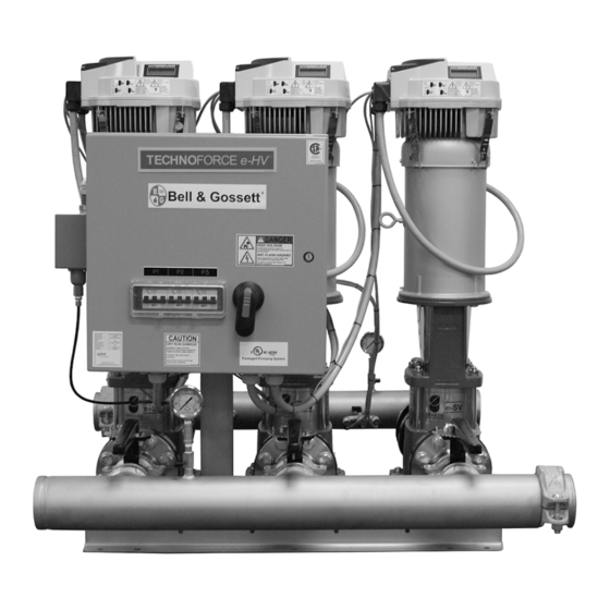
- Page 1 Mechanical Installation, Operation, and Maintenance Manual 10-001-287 Rev 4 TECHNOForce e-HV...
-
Page 3: Table Of Contents
Table of Contents Table of Contents 1 Introduction and Safety......................3 1.1 Introduction.......................... 3 1.2 Safety............................. 3 1.2.1 Safety terminology and symbols.................3 1.2.2 Protecting the environment..................4 1.3 User safety..........................4 1.3.1 Wash the skin and eyes....................5 2 Transportation and Storage...................... 7 2.1 Examine the delivery...................... - Page 4 Table of Contents 6.2 Monthly maintenance......................21 7 Troubleshooting........................23 7.1 Pump station troubleshooting..................23 7.1.1 The pump station does not power up..............23 7.1.2 The station powers up, but the pumps do not run..........23 7.1.3 The pumps run but do not build desired pressure..........24 7.1.4 The pump station experiences excessive vibration..........
-
Page 5: Introduction And Safety
This includes any modification to the equipment or use of parts not provided by Xylem. If there is a question regarding the intended use of the equipment, please contact a Xylem representative before proceeding. -
Page 6: Protecting The Environment
• Clean-up of spills Exceptional sites CAUTION: Radiation Hazard Do NOT send the product to Xylem if it has been exposed to nuclear radiation, unless Xylem has been informed and appropriate actions have been agreed upon. Recycling guidelines Always follow local laws and regulations regarding recycling. -
Page 7: Wash The Skin And Eyes
1 Introduction and Safety • Hard hat • Safety goggles, preferably with side shields • Protective shoes • Protective gloves • Gas mask • Hearing protection • First-aid kit • Safety devices NOTICE: Never operate a unit unless safety devices are installed. Also see specific information about safety devices in other chapters of this manual. - Page 8 1 Introduction and Safety WARNING: • Always disconnect and lock out power to the driver before you perform any installation or maintenance tasks. Failure to disconnect and lock out driver power will result in serious physical injury. The main station panel is equipped with a main station disconnect for completely powering down the system.
-
Page 9: Transportation And Storage
2 Transportation and Storage 2 Transportation and Storage 2.1 Examine the delivery 2.1.1 Examine the package 1. Examine the package for damaged or missing items upon delivery. 2. Record any damaged or missing items on the receipt and freight bill. 3. -
Page 10: Long Term Storage
– Storage location should also provide minimal exposure to vibration and other damage potentially transmitted from adjacent operating equipment. – Product supplied in factory cartons, pallets or similar Xylem packaging should be kept in ‘as-shipped’ condition where possible. – Inspect suction and discharge manifold flange covers. - Page 11 2 Transportation and Storage – Preparation for storage under these conditions is the same as for indoor and outdoor, except the suction and discharge piping will serve as flange covers. – The suction and discharge valves must be tightly closed and all water removed from the pump and attached piping.
-
Page 12: Product Description
3 Product Description 3 Product Description 3.1 General description Description A pump station is a pre-engineered and fabricated line of packaged booster systems that provides: • Energy efficiency • System protection • Hydraulic capability up to 780 GPM • Boost pressures up to 270 PSI Intended applications WARNING: This product can expose you to chemicals including Lead, which is known to the State of... - Page 13 3 Product Description Model Number Serial Number Station Voltage System FLA SCCR Largest Motor HP Station Flow Pump Boost Date Code Applied Water Solutions Dallas, Texas, U.S.A Customer Service 1.800.786.7480 Nameplate field Explanation Model number The manufacturer's number to indicate the particular type of product which has been acquired.
-
Page 14: Installation
4 Installation 4 Installation 4.1 Reference manuals Additional installation information For information on installing controllers, use the following IOM: • Hydrovar - Instruction Manual • Hydrovar - Overview Software Parameters 4.2 Field connections Diagrams Actual equipment manufacturers/models installed are system specific. Refer to specific manufacturer Installation, Operation, and Maintenance manuals for details unique to each component. -
Page 15: Foundation Requirements
4 Installation Guideline Explanation/comment If you require lifting equipment such as a hoist or tackle, This makes it easier to properly use the lifting equipment make sure that there is enough space above the pump and safely remove and relocate the components to a safe package. -
Page 16: Grout The Baseplate
4 Installation 4.7 Grout the baseplate Required equipment: • Cleaners: Do not use an oil-based cleaner because the grout will not bond to it. See the instructions provided by the grout manufacturer. • Grout: Non-shrink grout is required. 1. Clean all the areas of the baseplate that will come into contact with the grout. 2. -
Page 17: Commissioning, Startup, Operation, And Shutdown
5 Commissioning, Startup, Operation, and Shutdown 5 Commissioning, Startup, Operation, and Shutdown 5.1 Preparation for startup DANGER: Electrical hazard sufficient to kill. Always disconnect and lock out the power before you service the unit. WARNING: • Failure to follow these precautions before you start the unit will lead to serious personal injury and equipment failure. -
Page 18: Final Installation Checks
5 Commissioning, Startup, Operation, and Shutdown Checks Checked Check that the piping is clean and has been flushed. 5.1.2 Final installation checks Installation checklist CAUTION: Serious damage to the pump may result if it is started dry. Make sure that the pump is completely filled with liquid before it is started. -
Page 19: Connect The Storage Tank
5 Commissioning, Startup, Operation, and Shutdown a) Check all of the power wiring connections and secure them as required. b) Confirm with the owner/installing contractor if there are plans for any required building automation or remote connections. c) Inspect and/or install any customer remote terminations. 2. - Page 20 5 Commissioning, Startup, Operation, and Shutdown Figure 3: Terminals for probes connection 1. Level sensing probes connection to terminals X1:1 X1:3 Option-I: How to use or connect this relay to run the Hydrovar properly 1. Connect the level sensing probes to the terminals X1:1, X1:2, X1:3 (Min., Max. and Common).
-
Page 21: Check For Available Suction Water
5 Commissioning, Startup, Operation, and Shutdown 5.2.4 Check for available suction water 1. Open all supply, discharge, and pump isolation valves. Also open any other package valves. 2. Close the bypass valve if it is installed in the piping by others. 3. -
Page 22: Test The Package
5 Commissioning, Startup, Operation, and Shutdown – NSFD minimum run timer - 5 minutes – NFSD test PR timer - 20 seconds 4. Adjust any other settings in order to meet the needs of your system. 5.2.9 Test the package 1. -
Page 23: Maintenance
6 Maintenance 6 Maintenance 6.1 Precautions DANGER: Electrical hazard sufficient to kill. Always disconnect and lock out the power before you service the unit. WARNING: • This manual clearly identifies accepted methods for disassembling units. These methods must be adhered to. Trapped liquid can rapidly expand and result in a violent explosion and injury. - Page 24 6 Maintenance Note that there is going to be some harmonic vibration with the pumps and motor. Listen for excessive vibration or noise as this requires immediate service. Do not operate the pump if there is excessive vibration. • Confirm that the building cooling and ventilation systems are operating and clear of all obstructions.
-
Page 25: Troubleshooting
7 Troubleshooting 7 Troubleshooting 7.1 Pump station troubleshooting DANGER: • Personal injury hazard. Troubleshooting a live control panel exposes personnel to hazardous voltages. Electrical troubleshooting must be done by a qualified electrician. Failure to follow these instructions will result in serious personal injury, death, and/or property damage. -
Page 26: The Pumps Run But Do Not Build Desired Pressure
7 Troubleshooting Cause Remedy Automatic mode is faulty. Check to see if the pump can be run in Manual mode on the Hydrovars. The impeller is bound. Check to see if you can turn the pump by hand. Check for a bound impeller. -
Page 27: The Pump Station Does Not Shut Down And No Water Is Used
7 Troubleshooting Cause Remedy Pump station vibration dampers are missing or Check for properly installed pump station vibration improperly installed. dampers. Pumps are running off their design curve. Check the application. Is the system running in an open discharge condition (excessive flow rate)? For example, is the system filling a large irrigation line for the first time of the season? Air or gases are present in the pumped liquid. -
Page 28: Technical Reference
8 Technical Reference 8 Technical Reference 8.1 Pump station numbering system The pump station label located on the inside of the control enclosure door identifies the product code number for the various versions of the pump systems. This number is also the catalog number for the pump station. - Page 29 8 Technical Reference Tenth character: Pole-Hz-Phase 4 = 2-60-3 Eleventh character: Motor voltage C = 230-460 F = 208-230/460 Twelfth character: Motor enclosure 6 = TEPE (Premium TEFC) Thirteenth character: Seal material 0 = Carb-SilCar-Viton Fourteenth character: Pump split 1 = 100 + Standby 4 = 33/33/33 2 = 50/50 5 = 33/33/33 + Standby...
-
Page 30: Appendix
9 Appendix 9 Appendix 9.1 Installation drawings Duplex (208–230/3 and 460/3 Volt): 3SV to 5SV 1.12 7.01 25.24 TECHNOForce e-HV Mechanical Installation, Operation, and Maintenance Manual... - Page 31 9 Appendix Duplex (208–230/3) 10SV2 to 10SV8, 15SV1 to 15SV-4; Duplex (460/3): 10SV2 to 15SV5 14.57 1.57 22.05 TECHNOForce e-HV Mechanical Installation, Operation, and Maintenance Manual...
- Page 32 9 Appendix Duplex (208–230/3): 33SV10, 33SV11, 33SV22; Duplex (460/3): 15SV6 to 33SV 1.18 26.38 1.57 34.65 TECHNOForce e-HV Mechanical Installation, Operation, and Maintenance Manual...
- Page 33 9 Appendix Duplex (208–230/3): 10SV11, 15SV5 to 15SV8, 33SV20, 33SV21, 33SV31, 33SV32 1.18 26.38 1.57 38.58 TECHNOForce e-HV Mechanical Installation, Operation, and Maintenance Manual...
- Page 34 9 Appendix Triplex (208–230/3) 3SV to 10SV8, 15SV1 to 15SV4; Triplex (460/3) 3SV to 15SV5 14.57 1.57 36.02 TECHNOForce e-HV Mechanical Installation, Operation, and Maintenance Manual...
- Page 35 9 Appendix Triplex (208–230/3): 33SV10, 33SV11, 33SV22; Triplex (460/3 Volt): 15SV6 to 33SV 1.18 26.38 1.57 51.97 TECHNOForce e-HV Mechanical Installation, Operation, and Maintenance Manual...
- Page 36 9 Appendix Triplex (208–230/3): 10SV11, 15SV5 to 15SV8, 33SV20, 33SV21, 33SV31, 33SV32 1.18 26.38 1.57 59.84 Quadplex (208–230/3): 3SV to 10SV8, 15SV1 to 15SV4; Quadplex (460/3 Volt): 3SV to 15SV5 14.57 21/32 1.97 14.57 14.57 14.57 3.05 49.80 TECHNOForce e-HV Mechanical Installation, Operation, and Maintenance Manual...
- Page 37 9 Appendix Quadplex (208–230/3): 33SV10, 33SV11, 33SV22; Quadplex (460/3 Volt): 15SV6 to 33SV 1.18 26.38 1.57 70.87 Quadplex (208–230/3): 10SV11, 15SV5 to 15SV8, 33SV20, 33SV21, 33SV31, 33SV32 1.18 26.38 1.57 82.68 TECHNOForce e-HV Mechanical Installation, Operation, and Maintenance Manual...
-
Page 38: Product Warranty
10 Product warranty 10 Product warranty Commercial warranty Warranty. For goods sold to commercial buyers, Seller warrants the goods sold to Buyer hereunder (with the exception of membranes, seals, gaskets, elastomer materials, coatings and other "wear parts" or consumables all of which are not warranted except as otherwise provided in the quotation or sales form) will be (i) be built in accordance with the specifications referred to in the quotation or sales form, if such specifications are expressly made a part of this Agreement, and (ii) free from defects in material and... - Page 39 10 Product warranty Limited consumer warranty Warranty. For goods sold for personal, family or household purposes, Seller warrants the goods purchased hereunder (with the exception of membranes, seals, gaskets, elastomer materials, coatings and other "wear parts" or consumables all of which are not warranted except as otherwise provided in the quotation or sales form) will be free from defects in material and workmanship for a period of one (1) year from the date of installation or eighteen (18) months from the product date code, whichever shall occur first, unless a...
- Page 40 10 Product warranty To make a warranty claim, check first with the dealer from whom you purchased the product or visit www.xyleminc.com for the name and location of the nearest dealer providing warranty service. TECHNOForce e-HV Mechanical Installation, Operation, and Maintenance Manual...
- Page 44 The original instruction is in English. All non-English instructions are translations of the original instruction. Tel: (844) XYL-PUMP [844-995-7867] © 2019 Xylem Inc Fax: (888) 322-5877 Bell & Gossett is a trademark of Xylem Inc or one of its www.xylem.com/bellgossett subsidiaries. 10-001-287_4_en.US_2019-03_IOM_TECHNOForce e-HV...
Need help?
Do you have a question about the Bell & Gossett TECHNOForce e-HV Series and is the answer not in the manual?
Questions and answers