
Related Manuals for Xylem GOULDS hydrovar X


Summary of Contents for Xylem GOULDS hydrovar X
- Page 1 INSTRUCTION MANUAL IM410 REV A ® hydrovar X Smart Pump Range Integrated pump, motor & variable speed drive solutions powered by hydrovar X...
-
Page 3: Table Of Contents
Table of Contents Table of Contents 1 Introduction and Safety......................3 1.1 Introduction........................3 1.2 Safety..........................3 1.2.1 Safety message levels.................... 3 1.2.2 User safety......................4 1.2.3 Wash the skin and eyes..................5 1.3 Protecting the environment....................5 2 Transportation and Storage....................7 2.1 Examine the delivery..................... 7 2.1.1 Examine the package..................... - Page 4 7.2 Electrical specifications....................32 7.3 Compliance of radio frequency characteristics............32 7.4 Characteristics of inputs and outputs................33 7.5 Dimensions and weights....................34 8 Cybersecurity........................35 8.1 Xylem product cybersecurity..................35 8.2 Security recommendations for end-user..............35 ® hydrovar X Smart Pump Range INSTRUCTION MANUAL...
-
Page 5: Introduction And Safety
This includes any modification to the equipment or use of parts not provided by Xylem. If there is a question regarding the intended use of the equipment, please contact a Xylem representative before proceeding. -
Page 6: User Safety
1 Introduction and Safety Safety message level Indication A hazardous situation which, if not avoided, could WARNING: result in death or serious injury A hazardous situation which, if not avoided, could CAUTION: result in minor or moderate injury The possibility of electrical risks if instructions are Electrical Hazard: not followed in a proper manner •... -
Page 7: Wash The Skin And Eyes
• Clean-up of spills Exceptional sites CAUTION: Radiation Hazard Do NOT send the product to Xylem if it has been exposed to nuclear radiation, unless Xylem has been informed and appropriate actions have been agreed upon. Recycling guidelines Always follow local laws and regulations regarding recycling. - Page 8 1 Introduction and Safety Waste and emissions guidelines Do not dispose of equipment containing electrical components together with domestic waste. Collect it separately in accordance with local and currently valid legislation. ® hydrovar X Smart Pump Range INSTRUCTION MANUAL...
-
Page 9: Transportation And Storage
2 Transportation and Storage 2 Transportation and Storage 2.1 Examine the delivery 2.1.1 Examine the package 1. Examine the package for damaged or missing items upon delivery. 2. Record any damaged or missing items on the receipt and freight bill. 3. -
Page 10: Storage Guidelines
2 Transportation and Storage hydrovar X Smart Pump Product Line (e-SVX, e-HMX, and e-SVX) e-SVX e-HMX e-SHX 2.3 Storage guidelines Storage location The product must be stored in a covered and dry location free from heat, dirt, and vibrations. NOTICE: Protect the product against humidity, heat sources, and mechanical damage. -
Page 11: Product Description
3 Product Description 3 Product Description 3.1 General description This product is a variable speed pump unit equipped with the hydrovar X smart motor. The unit may be installed vertically or horizontally in accordance with the acceptable installation configurations of the individual pump products listed in this document. The unit is non self- priming. -
Page 12: Data Plates
3 Product Description 3.4 Data plates The data plate is a label showing: • The main product details • The identification code Approval and certifications For the approvals see the motor data plate. 3.4.1 hydrovar X nameplates Motor data plate 1. -
Page 13: Pump Nameplates
AB Hz FLUID ABC °F SINGLE PHASE – AMB TEMP -15°C TO 45°C THREE PHASE – AMB TEMP -15°C TO 50°C XYLEM INC. 1 GOULDS DR. AUBURN, NY USA www.xylem.com/goulds DRINKING WATER NSF/ANSI 61 & 372 1. Goulds Catalog Number 2. -
Page 14: Hydrovar X Design Layout
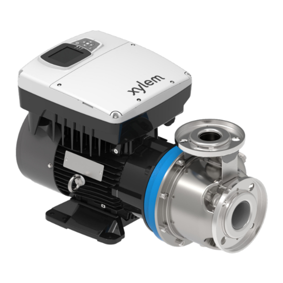
A/B/C ABC °F MAX DIA. BASIC MODEL DO NOT OPERATE AT CLOSED DISCHARGE MANUFACTURED IN USA XYLEM INC. 1 GOULDS DR. AUBURN, NY USA www.xylem.com/goulds DRINKING WATER NSF/ANSI 61 & 372 Energy Verified Only Énergie vérifiée seulement NOT APPLICABLE TO CANADA INDEXES 8 &... - Page 15 3 Product Description Figure 1: hydrovar X Smart Motor 1. Radio equipment approval sticker 2. Drive 3. Drive display 4. Date plate 5. Power supply and signal cable inlets 6. connection to the motor 7. Drive warning sticker Cable gland information Figure 2: Sizes B and C pre-assembled cable glands Table 1: Size B Number...
- Page 16 3 Product Description Number Description Cable Out Dia. in. [mm] Gland Plate Opening Dia. in. [mm] M12 cable gland with .145-.275 [3.7-7] .480 [12.2] Removable cable gland plate M4x12 hex socket 22.1 in-lb (2.5 Nm) button-head screws (x6) Table 2: Size C Description Cable Out Dia.
- Page 17 3 Product Description Number Description Cable Out Dia. in. [mm] Gland Plate Opening Dia. In. [mm] M12 cable gland with .145-.275 [3.7-7] .480 [12.2] Removable cable gland plate M4x12 hex socket 22.1 in-lb (2.5 Nm) button-head screws (x6) Other components and options Table 4: Other components and options Component Description...
-
Page 18: Installation
4 Installation 4 Installation 4.1 Mechanical installation 4.1.1 Installation area DANGER: Potentially explosive atmosphere hazard. The operation of the unit in environments with potentially explosive atmospheres or with combustible dusts (e.g.: wood dust, flour, sugars and grains) is strictly forbidden. Do not use the unit to handle hazardous or flammable liquid. -
Page 19: Hydraulic Installation
4 Installation Figure 4: Permitted positions Minimum spacing Condition Free distance surrounding motor To permit inspection and removal of the motor ≥ 12 in. [300 mm] To ensure proper ventilation and cooling ≥ 4 in. [100 mm] 4.2 Hydraulic installation •... - Page 20 4 Installation Figure 5: Single-pump system Figure 6: Multi-pump system 1. Pump with hydrovar X smart motor 2. Diaphragm pressure tank 3. Distribution panel 4. On-Off valve 5. Check valve 6. Low water control 7. Pressure gauge 8. Pressure sensor 9.
-
Page 21: Electrical Installation
4 Installation 4.3 Electrical installation 4.3.1 Precautions General precautions Before starting, make sure that the safety instructions shown in the Introduction and Safety chapterhave been fully read and understood. DANGER: The connection to the electric power supply must be completed by an electrician possessing the technical-professional requirements outlined in the current regulations. -
Page 22: Electrical Connection Guidelines
• The fuses shown in the table are suitable for use on a circuit capable of releasing 5000 Arms (symmetrical), maximum 480 V. With the indicated fuses, the short-circuit current rating (SCCR) for the drive is 5000 Arms. Xylem Three- Non-UL... -
Page 23: Residual Current Devices, Rcd (Gfci)
4 Installation Xylem Three- Non-UL UL fuses, type T, manufacturer and model MCBT model motor phase fuses, S203 Bussman Edison Littelfuse Ferraz- model/ power type gG, model Shawmut type supply voltage, Circuit Breaker EXM.../ 380-480 JJS-15 TJS (15) JLLS15 A6T15 4...B.. -
Page 24: Drive Guidelines
4 Installation 4.4 Drive guidelines 4.4.1 Drive assembly 1. Motor 2. Drive 3. Fastening screw 4. Seal 1. Lubricate the seal with alcohol. 2. Move the drive close to the motor. 3. Tighten the screws with a Torx spanner. Tightening torque: •... -
Page 25: Power Cable Installation
4 Installation 3. Cover screws 4. Phase conductors 5. Cable gland 6. Power supply cord 7. Protection conductor (ground) 8. Cover 9. Additional ground connection 4.4.3 Power cable installation 1. Remove the cover and observe the wiring diagrams inside. 2. Insert the power cable in the cable gland. 3. - Page 26 4 Installation Table 5: Position number Name Description Default setting Analog input 1 Power supply +24 VDC, Pressure sensor 1 max. 60 mA (total, terminals 1 + 5) Configurable analog input 1 Electronic GND Reserved For internal use, do not connect Analog input 2 Power supply +24 VDC,...
- Page 27 4 Installation Position number Name Description Default setting Digital Input 5 Configurable digital input Not selected 4, internal pull-up +24 VDC, contact current 6 Electronic GND 10 VDC power supply Power supply +10 VDC, max. 3 mA Electronic GND Communication Bus 1 RS485 port 1: RS485-1B Multipump N(-)
-
Page 28: Operation
• duty points insisting on unit maximum power • persisting undervoltage of mains, the life of the unit may be jeopardized and/or derating may occur: for further information contact Xylem or the Authorised Distributor. 5.2 Wait times Electrical Hazard: Contact with electric components may cause death, even after the unit has been switched off. -
Page 29: System Setup And Operation
6 System Setup and Operation 6 System Setup and Operation 6.1 Programming precautions NOTICE: • Carefully read and adhere to the following instructions before starting the programming activities to avoid incorrect settings that can cause malfunctions. • All modifications must be done by qualified technicians. 6.2 hydrovar X drive display and controls Table 6: Position number... -
Page 30: Graphic Display
6 System Setup and Operation Position number Name Function SEND button • Advancing through the menu levels • Confirm the selection of a parameter • Confirm the value of a parameter. Unit LED on Indicate that the unit is powered. Unit status LED Indicate: •... -
Page 31: Hydrovar X Parameter Menu
6 System Setup and Operation Table 7: Position number Name Description Header bar Shows static information and messages relating to the operating conditions, such as: • Alarms • Errors • Multi-pump operating. Main screen It shows the main information and allows the operating parameters to be changed. -
Page 32: Start The Unit
6 System Setup and Operation Position number Name Description Lower bar Shows: • On the left, the essential operating information, such as the actual adjustment value and the speed percentage at which the unit is operating • On the right, the buttons available for interaction in the main screen. -
Page 33: Error Reset For Hydrovar X
• Generate a work report • Contact the assistance service. Download the App and connect the mobile device with the unit 1. Download the Xylem X App to the mobile device from App Store or Google Play scanning the QR code: 2. -
Page 34: Technical Specification
-4° to 122°F (-20° to 50°C) Relative air humidity <50% at 104°F (40°C) NOTICE: If the humidity exceeds the stated limits, contact Xylem or the Authorized Distributor. Elevation <3280 ft (1000 m) above sea level. NOTICE: Tripping of the inverter's thermal protection. If the inverter is exposed to temperatures or installed at altitudes higher than those indicated, the unit's built-in automatic thermal protection fundtion may intervene. -
Page 35: Characteristics Of Inputs And Outputs
7 Technical Specification 1. This device may not cause harmful interference. 2. This device must accept any interference received, including interference that may cause undesired operation. The variable speed drive is considered like a mobile device, and it complies with the safety requirements for RF exposure in accordance with FCC rule part 2.1093 and KDB 447498 D01 as demonstrated in the RF exposure analysis. -
Page 36: Dimensions And Weights
7 Technical Specification Features Description Relay 2, with NC and NO changeover contact: • Relay 1 up to 240 VAC 0.25 A or 30 VDC 2 A • Relay 2 up to 30 VAC 0.25 A or 30 VDC 2 A WARNING: If relay 1 is connected to a voltage higher than 30 VAC, disconnect and do not use the terminals of relay 2. -
Page 37: Cybersecurity
This section reviews security features and provides guidance to help securely operate this product. For details and updates on Xylem product cybersecurity visit xylem.com/security 8.1 Xylem product cybersecurity... - Page 38 Display or via Modbus. Defining this process provides system resilience, including against ransomware. Implement specific inventory, Devices are hardened and Xylem ATT&CK for ICS: M0947 logging and monitoring of provides PSIRT to help NIST SP 800-53 Rev5: SM-8...
- Page 39 8 Cybersecurity For additional information see references: https://attack.mitre.org/mitigations/ics/ 1. ATT&CK for ICS available online: https://nvlpubs.nist.gov/nistpubs/ 2. NIST SP 800-53 Rev 5 available online: SpecialPublications/NIST.SP.800-53r5.pdf 3. ISA/IEC 62443 standards available for purchase from ISA, IEC, or ANSI. ® hydrovar X Smart Pump Range INSTRUCTION MANUAL...
- Page 40 For more information on how Xylem can help you, go to www.xylem.com Xylem Inc. Visit our Web site for the latest version of this document...
Need help?
Do you have a question about the GOULDS hydrovar X and is the answer not in the manual?
Questions and answers