
Related Manuals for Xylem Bell & Gossett VSX Series


Summary of Contents for Xylem Bell & Gossett VSX Series
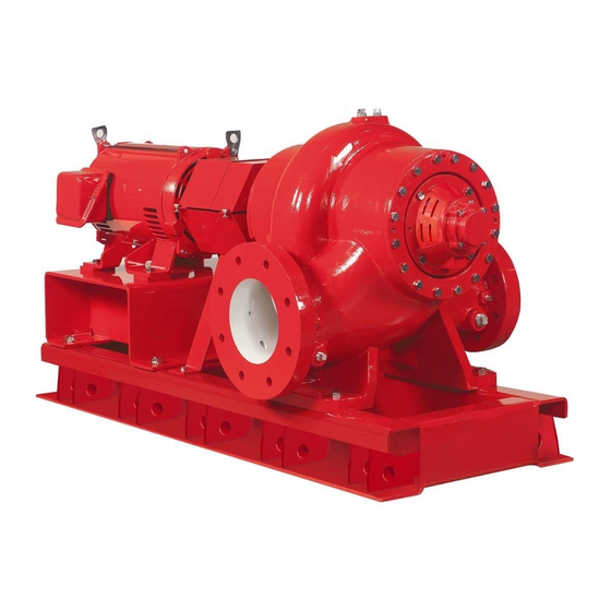
- Page 1 INSTRUCTION MANUAL P5002169 REVISION E INSTALLER: PLEASE LEAVE THIS MANUAL FOR THE OWNER’S USE. Series VSX VSH, VSC , and VSCS Models ® ® Centrifugal Pumps...
-
Page 2: Table Of Contents
TABLE OF CONTENTS INTRODUCTION .............. 1 TROUBLESHOOTING ............ 22 DESCRIPTION .............. 1 GUARDS ................24 PUMP APPLICATION ........... 1 ANSI/OSHA COUPLING GUARD OPERATIONAL LIMITS ..........1 REMOVAL/INSTALLATION ......24 Maximum Suction Pressure ........1 Removal ..............24 Maximum Working Pressure ......... 1 Installation ............. -
Page 3: Introduction
INTRODUCTION SEAL OPERATING LIMITS DESCRIPTION The Series VSX centrifugal pumps are frame- Mechanical Seals mounted pumps that feature high efficiency, NOTE: For use on closed or open systems rugged construction, compact design, foot- that are relatively free of dirt and/or other mounted volute, alignment-friendly coupling, and abrasive particles. -
Page 4: Pump Identification
PUMP IDENTIFICATION Bell & Gossett pumps are designated by a series of numbers such as Series VSX, Model VSH, VSC, or VSCS. The pump nameplate gives identification and rating information as shown in Figures 1 and 2. Permanent records for this pump are referenced by the serial number and it must be used with all correspondence and spare parts orders. -
Page 6: Additional Safety Instructions
ADDITIONAL SAFETY INSTRUCTIONS Electrical Safety WARNING: Rotating Components WARNING: Electrical Shock Hazard Hazard Electrical connections to be made by a qualified Do not operate the pump without all guards in electrician in accordance with all applicable codes, place. ordinances, and good practices. Failure to follow these instructions could result in Failure to follow these instructions could result in serious personal injury or death, or property... -
Page 7: General Instructions
GENERAL INSTRUCTIONS PURPOSE OF THE MANUAL SAFE HANDLING REQUIREMENTS This manual is furnished to acquaint you with WARNING: Falling Objects Hazard some of the practical ways to install, operate, and Eyebolts or lifting lugs, if provided, are maintain this pump. Read it completely before for lifting only the components to which any installation, operation, or maintenance on they are attached. - Page 8 Lifting the pump end only (bare pump) should be As an alternative to lifting by forklift, lifting done by placing one end of the slings around or devices can be used to lift the complete pump as close to the volute barrel as possible (See Fig. &...
-
Page 9: Location
LOCATION Important Locate the pump so there is sufficient room for Do not install and operate Bell & Gossett inspection, maintenance, and service. If the use of Pumps, 3D Valves, Suction Diffusers, etc., in a hoist or tackle is needed, allow ample head closed systems unless... -
Page 10: Base Plate Setting
BASE PLATE SETTING Place the pump unit on its concrete foundation, supporting it with steel wedges or shims. The wedges or shims should be machined and be put on both sides of each anchor bolt to provide a means for leveling the base. The wedge or shim width should be equal to or greater than the base rail width. -
Page 11: To Align Using Straight Edge And Calipers
3. Hold one half element on the hubs to determine the appropriate hub spacing. If using spacer elements with high speed rings, hold both half elements on the hubs to make sure the hubs do not interfere with the rings. The hubs may be installed with the hub extension facing in or out. -
Page 12: To Align Using Dial Indicator
Table 3: Angular Inch Gap Degrees Size 0.032 0.065 0.097 0.129 0.040 0.081 0.121 0.162 0.045 0.091 0.136 0.181 0.055 0.109 0.164 0.218 WE10 0.064 0.127 0.191 0.218 WE20 0.078 0.156 0.234 WE30 0.095 0.189 0.284 WE40 0.116 0.231 0.347 WE50 0.142 0.284... - Page 13 properly due to hub misalignment, rotate the shafts slightly. Torque all element and high speed ring capscrews to the values shown in Table 4. If possible, recheck angular and parallel alignments. WARNING: Flying Objects Hazard Coupling capscrews and set screws are to be installed using torque wrench or other torque measuring device.
-
Page 14: Final Alignment
Where flanged joints are used, ensure that inside Final Alignment diameters match properly. Final alignment cannot be accomplished until Remove burrs and sharp edges when making up the pump as been operated initially for a joints. sufficient length of time to attain operating temperature. -
Page 15: Suction Piping
Suction Piping When installing the suction piping, refer to the Hydraulics Institute Standards and observe the following precautions. (See Figure 14.) The sizing and installation of the suction piping is extremely important. It must be selected and installed so that pressure losses are minimized and sufficient liquid will flow into the pump when started and operated. -
Page 16: Valves In Suction Piping
Figure 15: Unbalanced Loading of a Double Suction Impeller Due to Uneven Flow Around an Elbow Adjacent to the Pump When operating on a suction lift, the suction Check valves are placed in the discharge pipe should slope upward to the pump piping in normal applications. -
Page 17: Pressure Gauges
may cause severe abrasion or corrosion of Pressure Gauges shaft sleeve, rapid packing Properly sized pressure gauges should be deterioration; they can even plug the stuffing installed in both the suction and discharge box flushing and lubrication system. The nozzles in the gauge taps. The gauges will stuffing box must be supplied at all times with enable the operator to easily observe the a source of clean, clear liquid to flush and... -
Page 18: Vee-Cut Impeller Trims
times, be supplied with flushing liquid at a high impeller diameter on the nameplate which is enough pressure to keep the box free from foreign chosen from the published performance curves. matter, which would quickly destroy the packing A vee-cut is required when the impeller diameter and score the shaft sleeve. - Page 19 Figure 18: Vee-cut Impeller Diameters...
-
Page 20: Operation
OPERATION FLUSHING PRE-START CHECKS New and old systems should be flushed to WARNING: Unexpected Startup Hazard eliminate all foreign matter. Heavy scale, welding splatter and wire or other large foreign matter can Disconnect and lockout power before servicing. clog the pump impeller. This will reduce the capacity of the pump causing cavitation, excessive Failure to follow these instructions could result in vibration, and/or damage to close clearance parts... -
Page 21: Starting
10. Check rotation. Be sure that the driver reference. Also record voltage, amperage per operates in the direction indicated by the phase, kilowatts if an indicating wattmeter is arrow on the pump casing as serious damage available, and pump speed. can result if pump is operated with incorrect 4. -
Page 24: Troubleshooting
TROUBLE SHOOTING Between regular maintenance inspections, be alert for signs of motor or pump trouble. Common symptoms are listed below. Correct any trouble immediately and AVOID COSTLY REPAIR AND SHUTDOWN. CAUSES CURES No Liquid Delivered 1. Lack of prime Fill pump and suction pipe completely with liquid. 2. - Page 25 CAUSES CURES Not Enough Pressure 20. Mechanical defects See items 14 and 15. 21. Obstruction in liquid passages Dismantle pump and inspect passages of impeller and casing. Remove obstruction. 22. Air or gases in liquid Install an air removal device or repair leaks in system piping. 23.
-
Page 26: Guards
GUARDS 1. Place the bottom inner guard into the bottom ANSI/OSHA COUPLING GUARD outer guard. REMOVAL/INSTALLATION 2. Hold the lower guards under the coupling and WARNING: Extreme Temperature slide the guard support(s) between the base Hazard and lower guards. If pump, motor, or piping are operating at extremely high or low temperatures, guarding or 3. -
Page 27: Bracket Guards
Figure 20: Installation/Removal Coupling Guard BRACKET GUARDS WARNING: Extreme Temperature Hazard If pump, motor, or piping are operating at extremely high or low temperatures, guarding or insulation is required. Failure to follow these instructions could result in serious personal injury or death, or property damage. -
Page 28: Service
SERVICE Figure 22: Mechanical View... -
Page 29: General Disassembly Procedures
maintenance and remove the GENERAL DISASSEMBLY PROCEDURES coupling hub on the pump. SHUTDOWN b. For spacer coupling assemblies: remove the coupling hub on the The following steps will address most normal pump. shutdowns of the pump, such as maintenance. Make any further adjustments of process piping, 3. -
Page 30: Disassembly Procedure To Remove Standard Mechanical Seals
11. Remove lip seals from both caps and the inboard bearing bracket. DISASSEMBLY PROCEDURE TO REMOVE STANDARD MECHANICAL SEALS 1. Loosen the set screws in the sleeve. 2. Remove the four gland assembly capscrews. 3. Remove the gland assembly and the sleeve from the shaft. -
Page 31: Disassembly Procedure To Remove Stuffing Box And Packing
10. Repeat steps 1 through 9 for the other side. Procedure to Remove Coverplates and Shaft Assembly – All Pumps. 11. If only the mechanical seals are to be replaced, proceed to the section entitled DISASSEMBLY PROCEDURE TO REMOVE Assembly Procedure to Install Standard CARTRIDGE SEALS Mechanical Seals. -
Page 32: Disassembly Procedure To Remove Coverplates And Shaft Assembly - All Pumps
Jacking Screw Cassette and Holes Sleeve Gland Figure 33: Cartridge Seal Gland and Service Figure 34: Removing the Coverplate Using Kit (Cassett and Sleeve) Jacking Screws 6. If only the cartridge seal or cartridge seal 3. Remove the volute gasket. cassette is to be replaced, proceed to the 4. - Page 33 Figure 36: Installing the Impeller Retaining Figure 38: Installing the Gasket on the Ring Coverplate Refer to Figure 52 to check that the impeller, 7. Using guide pins (threaded rod or a headless shaft, and volute are orientated correctly for bolt) threaded into...
-
Page 34: Assembly Procedure To Install Standard Mechanical Seals
Figure 40: View of the pump interior after one NOTE: Handle the seals with care. Clean the coverplate has been installed glands and seals before assembly. Take care not to damage the seals during assembly. 8. Install the volute capscrews. NOTE: Refer to Table 6 for all capscrew torque requirements. -
Page 35: Assembly Procedure To Install Stuffing Box And Packing
6. Install the four stuffing box capscrews. 7. Install set screws in the sleeve and tighten to 50 inch-lbs. NOTE: The last ring in each box may not be required until after the pump has operated for a period of time. 8. -
Page 36: Assembly Procedure To Install Bearing Frames - All Pumps
If installing a cartridge seal cassette, use P- 80 Rubber Lubricant Emulsion, soapy water, or equivalent to lubricate the static face o- ring. Slide the cassette onto the shaft ensuring the seal faces properly enter the cavity. Lightly tighten the cassette to the gland with capscrews. -
Page 38: To Change Rotation
TO CHANGE ROTATION Figure 52: Impeller to Volute Orientation WARNING: Unexpected Startup Hazard 1. Remove the pump from the base. Disconnect and lockout power before servicing. 2. Follow Disassembly Procedures applicable to the pump. Failure to follow these instructions could result in serious personal injury or death, or property NOTE: Only one of the coverplates must be damage. -
Page 39: To Change Standard Mechanical Seals
1 set of bearings TO CHANGE STANDARD MECHANICAL 1 set of wearing rings (if required) SEALS See the following sections: 1 set of casing gaskets, quad rings and lip seals GENERAL DISASSEMBLY INSTRUCTIONS 2 mechanical seals (complete) DISASSEMBLY PROCEDURE TO REMOVE BEARING FRAMES –... - Page 40 Table 6: Capscrew Torque Capscrew Torque (Foot-Pound) Capscrew Type Head Marking Capscrew Diameter 1 / 4 5/16 7/16 1 / 2 3 / 4 SAE Grade 2 Brass Stainless Steel SAE Grade 5 SAE Grade 8...
- Page 41 COMMERCIAL WARRANTY Warranty. For goods sold to commercial buyers, Seller warrants the goods sold to Buyer hereunder (with the exception of membranes, seals, gaskets, elastomer materials, coatings and other “wear parts” or consumables all of which are not warranted except as otherwise provided in the quotation or sales form) will be (i) be built in accordance with the specifications referred to in the quotation or sales form, if such specifications are expressly made a part of this Agreement, and (ii) free from defects in materi- al and workmanship for a period of one (1) year from the date of installation or eighteen (18) months...
- Page 42 LIMITED CONSUMER WARRANTY Warranty. For goods sold for personal, family or household purposes, Seller warrants the goods purchased hereunder (with the exception of membranes, seals, gaskets, elastomer materials, coatings and other “wear parts” or consumables all of which are not warranted except as otherwise provided in the quotation or sales form) will be free from defects in material and workmanship for a period of one (1) year from the date of installation or eighteen (18) months from the product date code, whichever shall occur first, unless a longer period is provided by law or is specified in the product documentation...
- Page 43 NOTES...
- Page 44 For more information on how Xylem can help you, go to www.xylem.com Xylem Inc. 8200 N. Austin Avenue Morton Grove, IL 60053 Phone: (847) 966-3700 Fax: (847) 965-8379 www.xylem.com/bellgossett Bell & Gossett is a trademark of Xylem Inc. or one of its subsidiaries. © 2019 Xylem Inc. P5002169E February 2019...
Need help?
Do you have a question about the Bell & Gossett VSX Series and is the answer not in the manual?
Questions and answers