
Related Manuals for Nordmann AT4 Series


Summary of Contents for Nordmann AT4 Series
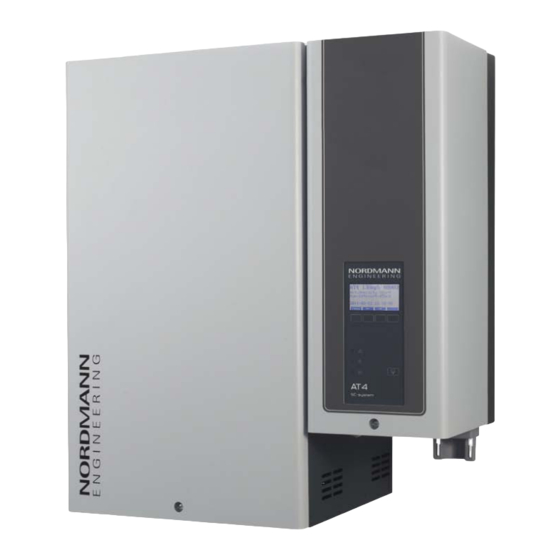
- Page 1 NORDMANN E N G I N E E R I N G Nordmann AT4 Steam humidifier MOUNTING INSTRUCTIONS 2559419 EN 1310...
-
Page 3: Table Of Contents
5.3.3 Inspecting the installed unit 5.4 Steam installation 5.4.1 Overview steam installation 5.4.2 Positioning of the steam distribution pipes 5.4.3 Installing the steam distributors 5.4.4 Positioning and mounting of the fan units FAN4 N... 5.4.5 Installing the steam and condensate hose 5.4.6 Common steam and condensate line errors 5.4.7 Inspecting the steam installation 5.5 Water installation 5.5.1 Overview water installation 5.5.2 Notes on water installation 5.5.3 Inspecting the water installation 5.6 Electric installation 5.6.1 Wiring diagram Nordmann AT4 single units 5.6.2 Wiring diagram Nordmann AT4 double units 5.6.3 Notes on electric installation 5.6.4 Inspecting the electrical installation Product specifications 6.1 Technical data 6.2 Unit dimensions... -
Page 4: Introduction
The steam humidifier Nordmann AT4 incorporates the latest technical ad van ces and meets all recognized safety standards. Nevertheless, improper use of the Nordmann AT4 may result in danger to the user or third parties and/or impairment of material assets. - Page 5 If the equipment changes hands, the documenta tion should be passed on to the new operator. If the documentation gets mislaid, please contact your Nordmann supplier. Language versions The present mounting instructions are available in various languages. Please contact your Nordmann supplier for information.
-
Page 6: For Your Safety
It is assumed that all persons working with the Nordmann AT4 are familiar and comply with the appropriate regulations on work safety and the preven tion of accidents. - Page 7 Danger that may arise from the unit: DANGER! Danger of electric hazard! The Nordmann AT4 is mains powered. One may get in touch with live parts when the unit is open. Touching live parts may cause severe injury or danger to life.
-
Page 8: Product Overview
Product Overview Models overview Steam air humidifiers Nordmann AT4 are available with different heating voltages and steam capacities ranging from 5 kg/h up to a maximum of 130 kg/h. Heating voltage ** Max. steam ca- Model Unit size pacity Nordmann AT4... -
Page 9: Identification Of The Unit
Identification of the unit The identification of the unit is found on the type plate: Type designation Serial number (7 digits) Month/Year Nordmann Engineering AG, CH-8808 Pfäffikon Heating voltage Typ: AT4 4564 Ser.Nr.: XXXXXXX 02.10 Heizspannung: 400V / 3~ / 50...60Hz Leistung: 33.8 kW Maximum steam capacity per unit Dampfleistung: 45.0 kg/h... -
Page 10: Steam Humidifier Construction
Steam humidifier construction figure shows medium unit Steam cylinder compartment Filling and draining hose Control compartment Water supply hose Main contactor Overflow hose Power board Inlet valve Connecting terminals Drain pump Type plate Drain cup Remote operating and fault indication board (option) Steam cylinder receptacle Cable openings Drain hose (manual drain) -
Page 11: Functional Description
Functional description The steam humidifier Nordmann AT4 is a pressureless steam generator that utilizes an electrode heating. The steam humidifier Nordmann AT4 is designed for air humidification via a steam distributor (steam distribution pipe, fan unit or steam distribution system MultiPipe). - Page 12 Upon reaching the requested steam capacity, the inlet valve closes. If the steam generation decreases below a certain percentage of the required capacity, due to lowering of the water level (e.g. because of the evapora tion process or drainage), the inlet valve opens until the required capacity is available again.
-
Page 13: Humidification System Overview
Humidification system overview System overview duct humidification (single units) MultiPipe System 1 System 2 DV41 DV71 DS22 DS35 KS10 DV71 DS35 KS10 Z261 125...1250 µS/cm Z261 1...10 bar 1...40 °C Steam humidifier Water drain hose (included in the delivery) Steam connector Service switch control voltage supply (building side) Water supply connector Service switch heating voltage supply (building side) Water drain connector... - Page 14 System overview duct humidification (double units) DS35 DV71 KS10 Z261 MultiPipe System 4 125...1250 µS/cm 1...10 bar 1...40 °C Steam humidifier Service switch control voltage supply (building side) Steam connector Service switch heating voltage supply module A (building side) Water supply connectors Service switch heating voltage supply module B (building side) Water drain connector Steam hose (accessory “DS35”)
- Page 15 System overview room humidification (single units) FAN4 N L ... W KS10 DS80 FAN4 N S ... W FAN4 N M ... W FAN4 N L ... W DS80 KS10 FAN4 N S ... D Z261 FAN4 N M ... D FAN4 N L ...
- Page 16 System overview room humidification (double units) FAN4 N L ... W DS80 KS10 DS80 KS10 FAN4 N L ... W Z261 FAN4 N L ... W KS10 125...1250 µS/cm 1...10 bar DS80 1...40 °C O FF O FF O FF Z261 Steam humidifier Water drain hose (included in the delivery)
-
Page 17: Options
(for mains supply without neutral lead) @-Link AT4 Configuration according to separate documentation Gateway to connect the Nordmann AT4 to a building management system. Two versions are available: BACnet/IP or LonWorks. Nordmann AT4... (400 V/3~/50...60 Hz) 1534... -
Page 18: Accessories
Accessories 3.7.1 Accessories overview Accessories for water installation Nordmann AT4... 1532 2362 3262 4564 4662 6462 6564 9064 13064 1534 2364 3264 6464 Filter valve Z261 (1 pc. per system) Accessories for steam installation Nordmann AT4... 1532 2362 3262 4564... -
Page 19: Accessory Details
Note: If the humidification distance (see chapter 5.4.2) has to be reduced for technical reasons, the amount of steam per unit must be divided between several steam distribution pipes or the steam distribution system Mul- tiPipe must be used. If this is the case, contact your Nordmann supplier. - Page 20 3.7.2.2 MultiPipe steam distribution system The MultiPipe steam distribution system is used in ventilation ducts with a short humidification distance (for the calculation of the humidification dis tance refer to chapter 5.4.2). When ordering an MultiPipe system the duct dimension must be specified. Please consult the data in the following table. MultiPipe Number of steam Max.
- Page 21 Note: Further information on the fan units FAN4... can be found in the sepa rate manual supplied with the fan unit. Important note regarding the IP protection class: If a Nordmann AT4 with fan unit FAN4 N... shall be operated without the fan unit at a later date (e.g.
-
Page 22: Standard Delivery
Always place the unit on its back side. Packaging Keep the original packaging of the Nordmann AT4 for later use. In case you wish to dispose of the packaging, observe the local regulations on waste disposal. Never dispose of the packaging to the environment. -
Page 23: Notes For The Planning Engineer
The total amount of losses depends on the entire system and must be taken into consideration when calculating the required steam capacity. If you have any questions regarding the calculation of the steam capacity please contact your Nordmann supplier. – For systems where the max. required steam capacity varies extensively (e.g. -
Page 24: Selecting The Unit
4.1.2 Selecting the unit Nordmann AT4 4564 400V3 Heating voltage ** Max. steam ca- Model Unit size pacity Nordmann AT4 Single Double in kg/h unit unit small medium large large 1534 2364 3264 400V3 (400 V/3~/50...60 Hz) 4564 6464 6564... -
Page 25: Selecting The Control System
Selecting the control system The various control systems – System 1: Room humidity control System 1 is suited for direct room humidification and air condition- ing systems with mainly recirculated air. The humidity sensor or humidistat respectively is preferably located in the room itself or in the exhaust air duct. - Page 26 — System 3 Direct room humidification System 1 — Please contact your Nordmann supplier, if your application meets the following conditions: – Humidification of small rooms up to 200 m – Air conditioning systems with a high number of air exchanges –...
-
Page 27: Mounting And Installation Work
Mounting and installation work Important notes for mounting and installation work Qualification of personnel All mounting and installation work must be carried out only by well quali- fied personnel authorised by the owner. It is the owner’s responsibility to verify proper qualification of the personnel. General note Strictly observe and comply with all information given in the present mounting instructions regarding the location of the unit and the installation of water,... -
Page 28: Installation Overviews
Installation overviews Installation overview duct humidification Heating voltage ** L1 L2 L3 A1 / A2 L1 L2 L3 ext. L1 L2 L3 400 V/3~/50..60 Hz 230 V/3~/50..60 Hz DV41 DV71 L1 L2 400 V/2~/50..60 Hz Pmax 1500 Pa min. 5 % –... - Page 29 System overview room humidification Heating voltage ** L1 L2 L3 ** on double units each module has a separate heating voltage supply L1 L2 L3 ext. L1 L2 L3 FAN4 N S ... W 400 V/3~/50..60 Hz 230 V/3~/50..60 Hz FAN4 N M ...
-
Page 30: Mounting The Unit
. 4 0 m i n . 2 5 m i n 1532 2362 3262 4564 4662 6462 6564 9064 13064 1534 2364 3264 6464 Nordmann AT4 ... Dimensions Housing dimensions in mm Weights Net weight in kg Operating weight in kg... - Page 31 CAUTION! If for some reason the Nordmann AT4 must be installed in a location without floor drain, it is mandatory to provide a leakage monitoring device to safely interrupt the water supply in case of leakage.
-
Page 32: Mounting The Humidifier
5.3.2 Mounting the humidifier Dimension Unit type 522, 524, 1532, 1534, 3262, 3264, 532, 534, 2362, 2364 4564, 6564 822, 824, 832, 834 204,0 mm 205.0 mm 205.0 mm 40,0 mm 50.0 mm 52.5 mm 150,0 mm 210.0 mm 260.0 mm Dimension Unit type 4662, 6462, 6464, 9064, 13064 203.0 mm... -
Page 33: Inspecting The Installed Unit
3. Unlock the screw(s) of the front panel(s) (steam side), then remove the front panel(s). 4. Unmount the steam cylinder(s) (see Nordmann AT4 operating instruc tions chapter 6.3.1). 5. Hang up the unit onto the wall support. Then, fix the unit to the wall support using the supplied screws “B”. -
Page 34: Steam Installation
Steam installation 5.4.1 Overview steam installation DV41 DV71 Pmax 1500 Pa min. 5 % – Pmin -800 Pa DS22 DS35 min. 20 % min. 20 % – KS10 FAN4 N S ... W FAN4 N M ... W FAN4 N L ... W min. -
Page 35: Positioning Of The Steam Distribution Pipes
5.4.2 Positioning of the steam distribution pipes The location for the steam distribution pipes should be determined at the time of dimensioning the air conditioning system. Please note the following instructions to ensure proper humidification of the duct air. Calculating the humidification distance The water vapour, emitting from the steam distribution pipes, requires a certain distance to be absorbed by the ambient air so that it is no longer visible as steam. - Page 36 MultiPipe must be used. If this is the case, contact your Nordmann supplier. Minimum distances to be observed To prevent the water vapour, that is emitting from the steam distribution pipe, from condensing on downstream system components, a minimum distance to the steam distribution pipe must be observed (depends on the humidifi...
- Page 37 before diffuser before control sensor before/after filter/register before/after fan, zone exit 1 . 5 * 2,5 x B before aerosol filter Installation notes and dimensions The steam distribution pipes are designed for either horizontal installation (on the duct wall) or, with accessories, for vertical installation (in the duct floor).
- Page 38 Positioning the steam distribution pipes in the duct In positioning the steam distribution pipes, the following dimensions should be observed: 1 / 2 1 / 2 2 / 3 1 / 3 H min.= 250 mm H ≥400 mm H min.= 200 mm 1 / 3 1 / 3 1 / 3...
-
Page 39: Installing The Steam Distributors
– Steam distribution pipes must not be mounted to round ducts. If you have questions relating to the dimensioning of ventilation ducts in combination with steam humidifiers Nordmann AT4, contact your Nordmann supplier. 5.4.3 Installing the steam distributors Detailed information on the installation of steam distribution pipes DV41... -
Page 40: Positioning And Mounting Of The Fan Units Fan4 N
FAN4 N... If you have questions concerning the direct room humidification, please contact your Nordmann supplier. Further information is provided in the separate installation and operating instructions for the corresponding fan unit. -
Page 41: Installing The Steam And Condensate Hose
5.4.5 Installing the steam and condensate hose Important! Use original steam and condensate hose from your Nordmann supplier exclusively. Other types of hoses can cause undesired operational malfunctions. Instructions for the hose layout The hose layout depends on the position of the steam distribution pipe: –... - Page 42 – Steam distribution pipe is mounted less than 500 mm above the top edge of the humidifier: min. 5 % – min. 20 % min. 20 % – Obstacle min. 20 % min. 20 % min. 5 % – min. 20 % min.
- Page 43 Note: If your particular installation exceeds the maximum steam hose length of 4 m contact your Nordmann representative. In any case, steam hoses longer than 4 m must be insulated in their entire length (e.g. with insulation hose “EcoTherm”).
- Page 44 Steam line with fixed piping For steam lines with fixed piping, the same instructions apply to the laying of the piping as already described. min. 20 % min. 20 % – Ømin. 200 mm The following additional notes should be observed: –...
-
Page 45: Common Steam And Condensate Line Errors
5.4.6 Common steam and condensate line errors 1. Steam hose not led at least 300 mm perpendicularly upwards before first bend. 2. Minimum bend radius of steam hose of 300 mm not maintained (forming of condensate). 3. Siphon of the condensate hose not at least 300 mm below the steam distribution pipe. -
Page 46: Inspecting The Steam Installation
5.4.7 Inspecting the steam installation Use the following check list to ascertain that the steam installation was performed correctly: – Steam distributors Steam distributors (steam distribution pipe or MultiPipe steam distri bution system) correctly positioned and secured (screws tightened)? Are the outlet orifices at right angles to the air flow direction? –... -
Page 47: Water Installation
Water installation 5.5.1 Overview water installation G 3/4" ø 31 mm ø 14/7 mm G 1/2" ø 31 mm G 3/4" G 3/8" Z261 125...1250 µS/cm 1...10 bar 1...40°C ≥ 40 mm G 3/8" G 3/4" ø 31 mm ø 14/7 mm G 1/2"... -
Page 48: Notes On Water Installation
– If the Nordmann AT4 shall be operated with softened or partly sof tened water, please contact your Nordmann supplier. – The connection material must be pressure-proof and certified for use in drinking water systems. -
Page 49: Inspecting The Water Installation
5.5.3 Inspecting the water installation Check the following topics: – Water supply Has filter valve (accessory “Z261”) or shutoff valve and 5 µm water filter respectively been installed in supply line? Have admissible water pressure (1 – 10 bar) and admissible tem perature (1 –... -
Page 50: Electric Installation
Electric installation 5.6.1 Wiring diagram Nordmann AT4 single units... -
Page 51: Wiring Diagram Nordmann At4 Double Units
5.6.2 Wiring diagram Nordmann AT4 double units... -
Page 52: Notes On Electric Installation
5.6.3 Notes on electric installation Important notes – The electric installation must be carried out according to the wiring dia gram in chapter 5.6.1, the notes on electric installation as well as the applicable local regulations. All information given in the wiring diagram must be followed and observed. - Page 53 The supply wiring is to be fed into the unit via the clamp strap on the bottom of the unit. Note: Double units have separate heating voltage supplies for each cylinder. Heating voltage Max. steam Nordmann Nominal power Nominal Main fuses F5 capacity AT4 ..
- Page 54 Control voltage supply CAUTION! – Before connecting, ensure that the mains voltage corresponds with the control voltage of the unit (230 V/1 50…60 Hz). – The humidifier must only be connected to a mains supply with a protective conductor. The connection to the control voltage is made in accordance with the wir ing diagram, to the terminal block “XE3”...
- Page 55 Remote operating and fault indication H1 (Option “RFI”) The optional remote operating and fault indication PCB is to be connected via a flat ribbon cable to the corresponding connector on the control board. The optional remote operating and fault indication PCB contains four potentialfree relay contacts for the connection of the following operating and fault indications: –...
- Page 56 Connection of the remote terminal (Option RP) The optional remote terminal is to be connected via a fourwire cable to the corresponding contacts of terminal block X15 on the power board of one of the humidifiers. Addtional humidifiers (max. 8) to be remote controlled are connected in series via the contacts “D+”...
- Page 57 Internal control voltage supply via option CVI or option Trafo – Option CVI (mains supply with neutral lead): For mains voltages of 400 V/3~/50...60 Hz, 400 V/2~/50...60 Hz and 230 V/3~/50...60 Hz. The option CVI is connected according to the fol lowing wiring diagram.
-
Page 58: Inspecting The Electrical Installation
5.6.4 Inspecting the electrical installation Check the following points: Do the supply voltages for heating and control comply with the relevant voltages given in the wiring diagram? Is the correct CF Card inserted? Are the voltage supplies (heating and control voltage) correctly fused? Are the service switches “Q..”... -
Page 59: Product Specifications
Internal control voltage supply 1xS-CVI 1xM-CVI 1xL-CVI Transformer 400V/230V Trafo @Link AT4 @Link AT4 Accessories Filter valve 1x Z261 Nordmann AT4 Remote Terminal Steam distribution pipe 1xDV41-... 1xDV71-... 2xDV71-... 4xDV71-... Steam distribution system MultiPipe ––– System 1 System 2 System 4... -
Page 60: Unit Dimensions
Unit dimensions Nordmann AT4 5../8.. (Dimensions in mm) G 3/4”... - Page 61 Nordmann AT4 15../23.. (Dimensions in mm) G 3/4”...
- Page 62 Nordmann AT4 32../4564/6564 (Dimensions in mm) 52.5 G 3/4”...
- Page 63 Nordmann AT4 4662/6462/6464/9064/13064 (Dimensions in mm) G 3/4” G 3/4” 43.5...
- Page 64 Notes...
- Page 65 Notes...
- Page 66 Notes...
- Page 67 © Nordmann Engineering Ltd., Printed in Switzerland Technical modifications reserved...
- Page 68 NORDMANN E N G I N E E R I N G Reg.No. 40002-2 NORDMANN Manufacturer: Nordmann Engineering Ltd. E N G I N E E R I N G www.nordmann-engineering.com, info@nordmann-engineering.com...
Need help?
Do you have a question about the AT4 Series and is the answer not in the manual?
Questions and answers