
Subscribe to Our Youtube Channel
Related Manuals for Nordmann RC4


Summary of Contents for Nordmann RC4
- Page 1 Nordmann RC4/DC4 Electrode Humidifiers NORDMA Dampfluftbefeuchter E N G I N E E R MouNtiNg iNstRuCtioNs NORDMANN E N G I N E E R I N G...
-
Page 3: Table Of Contents
Inspecting the installed unit 5.3 Steam installation 5.3.1 Overview steam installation 5.3.2 Positioning and mounting of the steam distribution pipe 5.3.3 Installing the steam distributors 5.3.4 Installing the steam hose 5.3.5 Installing the condensate hose 5.3.6 Inspecting the steam installation 5.4 Water installation 5.4.1 Overview water installation 5.4.2 Notes on water installation 5.4.3 Inspecting the water installation 5.5 Electric installation 5.5.1 Wiring diagram Nordmann RC4/DC4 5.5.2 Notes on electric installation 5.5.3 Inserting the CF card 5.5.4 Inspecting the electrical installation Product specifications 6.1 Technical data Unit dimensions 6.3 Declaration of conformity... -
Page 4: Introduction
Introduction To the very beginning We thank you for having purchased the steam humidifier Nordmann RC4/DC4. The steam humidifier Nordmann RC4/DC4 incorporates the latest technical ad v an c es and meets all recognized safety standards. Nevertheless, improper use of the Nordmann RC4/DC4 may result in danger to the user or third parties and/or impairment of material assets. To ensure a safe, proper, and economical operation of the steam humidifier Nordmann RC4/DC4, please observe and comply with all information and safety instructions contained in the present manual as well as the instructions given in the manuals for the components used in the humidifica- tion system. If you have questions, which are not or insufficiently answered in this documentation, please contact your Nordmann supplier. They will be glad to assist you. Notes on the mounting instructions Limitation The subject of these mounting instructions is the steam humidifier Nordmann RC4/DC4 its different versions. The various accessories are only described insofar as this is necessary... - Page 5 The catchword “WARNING” used in conjunction with the general caution symbol designates safety and danger notes in this documentation that, if neglected, may cause to injury to persons. DANGER! The catchword “DANGER” used in conjunction with the general caution symbol designates safety and danger notes in this documentation that, if neglected, may lead to severe injury or even death of persons. Safekeeping Please safeguard these mounting instructions in a safe place, where it can be immediately accessed. If the equipment changes hands, the documentation should be passed on to the new operator. If the documentation gets mislaid, please contact your Nordmann supplier. Language versions These mounting instructions is available in various languages. Please contact your Nordmann sup- plier for information. Copyright protection The present mounting instructions are protected under the Copyright Act. Passing-on and reproduc- tion of the manual (or part thereof) as well as exploitation and communication of the contents are prohibited without written permission by the manufacturer. Violation of copyright terms is subject to legal prosecution and arises liability for indemnification. The manufacturer reserves the right to fully exploit commercial patent rights.
-
Page 6: For Your Safety
For safety and warranty reasons any action beyond the scope of this manuals must be carried out only by qualified personnel authorised by the manufacturer. It is assumed that all persons working with the Nordmann RC4/DC4 are familiar and comply with the appropriate regulations on work safety and the prevention of accidents. Intended use The steam humidifier Nordmann RC4/DC4 is intended exclusively for air humidification via a steam distributor approved by the manufacturer (unit versions Nordmann DC4) or via the integrated ventilation unit (unit versions Nordmann RC4) within the specified operating conditions (see chapter 6 “Product specifications”). Any other type of application without the express written consent of the manufacturer is considered as not conforming with the intended purpose and may lead to the Nordmann RC4/DC4 becoming dangerous. Operation of the equipment in the intended manner requires that all the information in these in- structions is observed (in particular the safety instructions). Danger that may arise from the unit:... - Page 7 Behaviour in case of danger All persons working with the Nordmann RC4/DC4 are obliged to report any alterations to the unit that may affect safety to the owner without delay and to secure such a unit against accidental power- Prohibited modifications to the unit No modifications must be undertaken on the Nordmann RC4/DC4 without the express written consent of the manufacturer. For the replacement of defective components use exclusively original accessories and spare parts available from your Nordmann supplier.
-
Page 8: Product Overview
Product Overview Models overview Steam air humidifiers Nordmann RC4/DC4 are available in the two basic versions for duct air humidification and direct room air humidification with different heating voltages and steam capacities of 2 kg/h and 4 kg/h. Model Nordmann Duct Room Max. steam capacity 2 kg/h 4 kg/h 2 kg/h 4 kg/h Heating voltages 230V1~ / 50..60Hz... -
Page 9: Steam Humidifier Construction
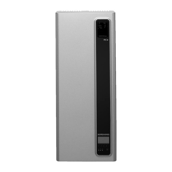
3.3 Steam humidifier construction Construction Nordmann 13 12 1 Back panel 14 Type plate 2 Water cup 1 5 Remote operating and fault indication board 3 Water supply hose (Option) 4 Heating electrodes 1 6 Control board with CF card Filling hose Unit switch 6 Overflow hose 1 8 Drain key 7 Steam cylinder 1 9 Display and control unit 8 Inlet valve (not visible) - Page 10 Construction Nordmann 13 12 1 Back panel 14 Type plate 2 Water cup 1 5 Remote operating and fault indication board 3 Water supply hose (Option) 4 Heating electrodes 1 6 Control board with CF card Filling hose Unit switch 6 Overflow hose 1 8 Drain key 7 Steam cylinder 1 9 Display and control unit 8 Inlet valve (not visible) 2 0 Operation status indicators (LED's)
-
Page 11: Functional Description
Functional description The steam humidifier Nordmann RC4/DC4 is a pressureless steam generator that utilizes an elec- trode heating. The steam humidifier Nordmann RC4/DC4 is designed for air humidification via a steam distributor (unit versions Nordmann DC4) or via the integrated ventilation unit (unit versions Nordmann RC4). Steam generation Any time steam is requested, the electrodes are supplied with voltage. Simultaneously, the inlet valve opens and water enters the steam cylinder from the bottom via water cup and supply line. As soon as the electrodes come in contact with the water, current begins to flow between the electrodes, eventually heating and evaporating the water. The more the electrode surface is exposed to water, the higher is the current consumption and thus the steam capacity. Upon reaching the requested steam capacity, the inlet valve closes. If the steam generation de- creases below a certain percentage of the required capacity, due to lowering of the water level (e.g. -
Page 12: Humidification System Overview
3.5 Humidification system overview System overview Nordmann 41-.. min. 5 % – DS22 Pmax. 800 Pa min. 10 % Pmin. -800 Pa – KS10 min. 20 % 41-.. min. 5 % – Pmax. 800 Pa Pmin. -800 Pa min. 10 % –... - Page 13 System overview Nordmann G 3/4" ø22 mm min. 10 % Z261 – G 3/8" ø10/8 mm DS22 125...1250µS/cm 1...10 bar ≥ 40 mm 1...40 °C min. 10 % – 1 Steam humidifier 6 Manometer (installation recommended) 2 Ventilation unit 7 Funnel with siphon (building side) 3 Water supply connector 8 Water drain hose (accessory “DS22”)
-
Page 14: Options
Options Nordmann Cable glands set with counter nuts 1x CG – 1x M20 for cable diameters from 7.0 to 13.0 mm – 1x M16 for cable diameters from 4.5 to 10.0 mm – 1x M12 for cable diameters from 2.5 to 6.5 mm Radio humidity sensor 1x RH Radio humidity sensor set consisting of radio humidity sensor and receiver board for the humidity control via the internal P/PI humidity controller. The maximum range of the radio humidity sensor in an open room is 25 m Note: the radio humidity sensor as well as the receiver board must be installed and configured only by a service technician of your Nordmann representative. Water drain hose 1x WDH Water drain hose to lead the drain line through the back panel of the unit. -
Page 15: Accessory Details
3.7.2 Accessory details 3.7.2.1 Steam nozzle W21 The steam nozzle W21 can be mounted in the ventilation duct horizontally or vertically. Keep a minimum distance clearance (A) of 200 mm between nozzle opening and the opposite duct wall. 3.7.2.2 Steam distribution pipe 41-... The steam distribution pipes are selected on the basis of the duct width (for horizontal installation) or the duct height (for vertical installation) and the capacity of the steam humidifier. Important! Always select the longest possible steam distribution pipe (opti m um humidification dis- tance). Steam distribution pipes Length (L) steam Duct width (B) Type 41-... -
Page 16: Standard Delivery
Standard delivery The standard delivery includes: – Steam humidifier Nordmann RC4/DC4 equipped with the options ordered according to chapter 3.6, fixing set, mounting instructions (this document) and operating instructions, packaged in cardboard box (W x H x D: 351 mm x 729 mm x 265 mm, shipping weight: 7.4 kg) – Ordered accessories with operating instructions according chapter 3.7, packed separately – Spare parts list Storing/Transportation/Packaging Storing Store the unit in a protected area meeting the following requirements: – Room temperature: 1 ... 40 °C – Room humidity: 10 ... 75 %rh Transportation For optimum protection always transport the unit in the original packaging. Always place the unit on its back side. Packaging Keep the original packaging of the Nordmann RC4/DC4 for later use. In case you wish to dispose of the packaging, observe the local regulations on waste disposal. Never... -
Page 17: Notes For The Planning Engineer
Notes for the planning engineer Selecting the unit version To select the unit version the following steps are required: 1. Selecting the unit version from the table in chapter 4.1.1 2. Calculating the required maximum steam capacity according chapter 4.1.2 4.1.1 Selecting the unit Nordmann 230V1 Model Nordmann Duct Room Heating voltages 230V1 230V1~ / 50..60Hz 240V1 240V1~ / 50..60Hz 200V2 200V2~ / 50..60Hz Max. steam capacity 2 kg/h 4 kg/h 2 kg/h 4 kg/h Integrated ventilation unit ––– Display and control unit External On/Off control... -
Page 18: Calculating The Maximum Required Steam Capacity
4.1.2 Calculating the maximum required steam capacity The maximum required steam capacity must be calculated based on one of the following formulas: Nordmann DC4 230V1 V • ρ • (x • (x 1000 1000 • ε : maximum steam demand in kg/h V: volume of supply air portion per hour in m /h (for indirect room humidification) or room volume to be humidified per hour in m /h (for direct room humidification) specific gravity of air in kg/m ρ: specific volume of air in m ε: : desired absolute room air humidity in g/kg : minimum absolute supply air humidity in g/kg The values for ρ, ε, x and x can be gathered from the h,x-diagram or the Carrier-Diagram for moist air respectively. Important notes: – The required maximum steam capacity depends on the specific application and the installation. -
Page 19: Selecting The Control System
Selecting the control system The steam humidifiers Nordmann RC4/DC4 are designed to be controlled with On/Off control via an external humidistat or with continuous control via an external P/PI humidity controller or the internal P/PI humidity controller. – System 1: Room humidity control System 1 is suited for direct room humidification and air conditioning systems with mainly recirculated air. The humidity sensor or humidistat respectively is preferably located in the room itself or in the exhaust air duct. Nordmann humidity sensor B1 ventilation interlock B2 airflow monitor B3 safety humidistat B4 humidistat internal P/PI controller external continuous controller (e.g. PI controller) input signal from A1 Nordmann humidity sensor B1 ventilation interlock... - Page 20 A1/2 humidity sensor B1 ventilation interlock B2 airflow monitor B3 safety humidistat Internal P/PI controller External continuous controller (e.g. PI controller) input signal from A1 input signal from A2 Please contact your Nordmann supplier, if your application meets the following conditions: – Humidification of small rooms up to 200 m – Air conditioning systems with a high number of air exchanges – Systems with variable air volume flow – Test facilities with extreme control accuracy requirements – Rooms with a high variation in max. steam capacity – Systems with temperature fluctuations – Cold rooms and systems with dehumidification...
-
Page 21: Mounting And Installation Work
Mounting and installation work Important notes for mounting and installation work Qualification of personnel All mounting and installation work must be carried out only by well qualified personnel authorised by the owner. It is the owner’s responsibility to verify proper qualification of the personnel. General note Strictly observe and comply with all information given in the present mounting instructions regarding the location of the unit and the installation of water, steam and electricity. Observe and comply with all local regulations dealing with water, steam and electrical installa- tions. Safety Some installation work requires removal of the unit cover. Please note the following: DANGER! Danger of electrical shock! You may get in touch with live parts when the unit is open. The steam humidifier must be connected to the mains only after all mounting and installation work has been completed and the cover has been relocated properly. CAUTION! The electronic components inside the humidifier are very sensitive to electrostatic discharge. When the unit is open for installation work, appropriate measures must be taken to protect these components against damage caused by electrostatic discharge (ESD protection). -
Page 22: Mounting The Unit
Mounting the unit 5.2.1 Notes on locating and mounting the unit Nordmann Note: The minimum spaces apply for a room atmosphere of 15 °C and max. . 2 5 m i n 60 %rh. For lower temperatures and/ or higher humidity the values should be adjusted accordingly . 2 5 m i n 2 6 5... - Page 23 To ensure proper functioning of the steam humidifier and to obtain an optimal efficiency, the follow- ing points must be considered and observed when choosing the location for the steam humidifier: – Install the steam humidifier in such a manner that it is freely accessible with sufficient space available for maintenance purposes. The minimum distances shown in the preceding figure must be maintained. – Install the steam humidifier Nordmann DC4 so that the length of the steam hose is kept as short as possible (max. 4 m) and that the minimum bend radius (R= 300 mm) and up-slope (20 %) or down-slope (5 %) of the steam hose is observed (see chapter 5.3.4). – During operation steam is blown out via the outlet opening of the steam humidifiers Nordmann RC4. Therefore, locate the steam humidifiers Nordmann RC4 in such a way, that no persons can be hurt by the steam flow. – The steam humidifiers Nordmann RC4/DC4 are designed for wall-mounting. Make sure that the construction (wall, pillar, floor-mounted console, etc.) to which the humidifiers are to be mounted, offers a sufficiently high load-bearing capacity (take notice of the weight information found in the dimension sand weights table above), and is suitable for the installation.
-
Page 24: Mounting The Humidifier
5.2.2 Mounting the humidifier Wall break-through to lead the connecting cables as well as the water supply pipe and the water drain hose (option WDH) through rear wall into the unit Procedure 1. Mark the attachment points “A” on the wall with the assistance of a spirit level. 2. Drill the holes for the attachment points “A” (diameter: 8 mm, depth: 40 mm), then insert the sup- plied plastic plugs. 3. Fix the wall support with the two long screws and washers “B”. Before tightening the screws, adjust the wall support vertically and horizontally with the spirit level. 4. Hang the unit up onto the wall support. 5. Loosen the fixing screw of the front cover on the bottom side of the unit a few turns, then remove the front cover. 6. Remove all transportation locks (steam clinder, drain pump, water cup) inside the unit. 7. Undo the steam cylinder: release the hose clamp on the steam connector of the steam cylinder, then detach the steam hose from the steam connector. Remove the plugs from the electrodes and from the level sensor. Carefully lift steam cylinder out of the cylinder receptacle, then remove it to the front. 8. Undo the two screws of the intermediate panel. Then, carefully remove the intermediate panel to the front, swivel it to the left and hang it onto the pins of the back panel. 9. Fix unit to the wall support using the two screws “C” and to the wall using the screw and washer “D”. Before tightening the screws, readjust the unit vertically with the spirit level. 10. A ssemble the unit in the reverse sequence. -
Page 25: Inspecting The Installed Unit
5.2.3 Inspecting the installed unit Check the following points: Is the unit installed in the correct place (see chapter 5.2.1)? Is the supporting surface stable enough? Is the unit correctly aligned, vertically and horizontally? Is the unit properly secured (see chapter 5.2.2)? Are all transportation locks inside the unit removed? Is the unit reassembled correctly and the front panel fixed with the screw? -
Page 26: Steam Installation
Steam installation 5.3.1 Overview steam installation 41-.. min. 5 % – Pmax. 800 Pa Pmin. -800 Pa min. 10 % – min. 20 % KS10 DS22 41-.. min. 5 % – Pmax. 800 Pa Pmin. -800 Pa min. 10 % –... -
Page 27: Positioning And Mounting Of The Steam Distribution Pipe
5.3.2 Positioning and mounting of the steam distribution pipe The location for the steam distribution pipes should be determined at the time of dimensioning the air conditioning system. Please note the following instructions to ensure proper humidification of the duct air. Calculating the humidification distance The water vapour, emitting from the steam distribution pipes, requires a certain distance to be absorbed by the ambient air so that it is no longer visible as steam. This distance is referred to as humidification distance “B ” and serves as a basis for the determination of the minimum distances from the upstream components in the system. Humidification Expansion and mixing zone distance B ϕ1: Supply air humidity before humidification ϕ2: Supply air humidity after humidification The calculation of the humidification distance “B ” is dependent on several factors. For a rough estimation of the humidification distance “B ”, the following table is useful. Recommended standard... - Page 28 Minimum distances to be observed To prevent the water vapour, that is emitting from the steam distribution pipe, from condensing on downstream system components, a minimum distance to the steam distribution pipe must be observed (depends on the humidification distance “B ”). before/after constriction after expansion before bend before branch before diffuser before control sensor before/after filter/register before/after fan, zone exit 1.5 x B 5 cm 2,5 x B before aerosol filter Installation notes and dimensions The steam distribution pipes are designed for either horizontal installation (on the duct wall) or, with accessories, for vertical installation (in the duct floor). The outlet orifices should always point upwards and at right angles to the airflow. If possible, the steam distribution pipes should be installed on the pressure side of the duct (max. duct pressure 800 Pa). If the steam distribution pipes are installed on the suction side of the duct, the maximum vacuum must not exceed 800 Pa.
-
Page 29: Installing The Steam Distributors
H min.= 250 mm H ≥400 mm H min.= 200 mm . = 2 m i n Guidelines for dimensioning the ventilation ducts – To facilitate the installation of the steam distribution pipes and for control purposes, a sufficiently sized control opening should be planned. – Within the range of the humidification distance, the ventilation duct should be waterproofed. – Air ducts passing through cold rooms should be insulated to prevent the humidified air from con- densing along the duct wall. – Poor airflow conditions within the air duct (e.g. caused by obstacles, tight bends, etc.) can lead to condensation of the humidified air. – Steam distribution pipes must not be mounted to round ducts. If you have questions relating to the dimensioning of ventilation ducts in combination with steam humidifiers Nordmann DC4, contact your Nordmann supplier. 5.3.3 Installing the steam distributors Detailed information on the installation of the steam nozzle W21 and the steam distribution pipe 41-... can be found in the separate mounting instructions for this products. -
Page 30: Installing The Steam Hose
5.3.4 Installing the steam hose Important! Use original Nordmann steam hose exclusively. Other types of steam hoses can cause undesired operational malfunctions. Instructions for the hose layout The hose layout depends on the position of the steam distribution pipe: – Steam distribution pipe is mounted more than 300 mm above the top edge of the humidifier: min. 5 % min. 20 % min. 20 % Initially, lead the steam hose with an upslope of at least 20% over a minimum height of 300 mm above the top edge of the unit, then lead the hose with a minimum upslope of 20% and/or a minimum downslope of 5% to the steam distribution pipe. -
Page 31: Installing The Condensate Hose
– The minimum bend radius for solid pipes is 4-5 x internal diameter. – Connection of the steam pipes to the steam distribution pipe and steam humidifier is effected by means of short lengths of steam hose secured with hose clamps. – Important! Allowance must be made for a pressure loss of 10 mm water column (approx. 100 Pa) per meter length or per 90° bend. 5.3.5 Installing the condensate hose Important! Use original Nordmann condensate hose exclusively. Other types of hoses can cause operational malfunctions. The hose layout depends on the position of the steam distribution pipe: – Steam distribution pipe is mounted more than 300 mm above the top edge of the humidifier: min. 20 % min. 20 % Lead the condensate hose down to the humidifier with a minimum slope of 20 %, in the form of a siphon (min. -
Page 32: Inspecting The Steam Installation
– Steam distribution pipe is mounted less than 300 mm above the top edge of the humidifier: min. 20 % min. 20 % Lead the condensate hose down with a minimum slope of 20 %, in the form of a siphon (min. hose bend diameter Ø200 mm), directly into a discharge funnel. Important! Before putting the unit into operation, the siphon of the condensate hose must be filled with water. 5.3.6 Inspecting the steam installation Use the following check list to ascertain that the steam installation was performed correctly: – Steam distributor Steam distributors (steam distribution pipe or steam nozzle) correctly positioned and se- cured? Are the outlet orifices at right angles to the air flow direction? – Steam hose... -
Page 33: Water Installation
ø10/8 mm Z261 ≥ 40 mm 125...1250µS/cm 1...10 bar 1...40 °C min. 10 % – 5.4.2 Notes on water installation For the connection of the water supply line and the water drain line, the unit must be opened. Proceed as follows: loosen the fixing screw of the front cover on the bottom side of the unit a few turns, then remove the front cover. Undo the two screws of the intermediate panel. Then, carefully remove the intermediate panel to the front, swivel it to the left and hang it onto the pins of the back panel. Water supply The water supply is to be carried out according to the figure found in chapter 5.4.1 and the applicable local regulations for water installations. The indicated connection specifications must be observed. – The installation of the filter valve (accessory “Z261”, alternatively a shut-off valve and a 5 µm water filter can be used) should be made as close as possible to the steam humidifier. – Admissible mains pressure 1.0 to 10.0 bar (hammer-free system) For mains pressures >10 bar, the connection must be made via a pressure reducing valve (ad- justed to 1.0 bar). For mains pressures <1.0 bar please contact your Nordmann supplier. -
Page 34: Inspecting The Water Installation
– Notes on water quality: – For the water supply of the Nordmann RC4/DC4, use exclusively untreated drinking wa- ter. – The use of additives such as corrosion inhibitors, disinfectants, etc. is not allowed, since these additives may endanger health and affect proper operation. – If the Nordmann RC4/DC4 shall be operated with softened or partly softened water, please contact your Nordmann supplier. – The connection material must be pressure-proof and certified for use in drinking water systems. – Important! Before connecting the water line, the line should be well flushed out. CAUTION! The thread at the humidifier connection is made of plastic. To avoid overtightening, the union nut of the water pipe must be tightened by hand only. Water drain The water drain is to be carried out according to the figure found in chapter 5.4.1 and the applicable local regulations for water installations. The indicated connection specifications must be observed. – Make sure that the drain pipe is correctly fixed and easily accessible for inspections and cleaning purposes. – The draining temperature is: 80…90 °C. Use temperature-resistant installation materials only! 5.4.3 Inspecting the water installation Check the following topics: – Water supply... -
Page 35: Electric Installation
Electric installation 5.5.1 Wiring diagram Nordmann RC4/DC4 Control board Power board CYLINDER LEVEL SENSOR DRAIN INLET FAN- FAN+ CF Card Driver REL4 CR1632 MAIN CONTACT Fault Remote J1 CPU BOARD 200mAF MAIN SUPPLY Keypad / LED F4 1AT N L SW N SW... -
Page 36: Notes On Electric Installation
– The electric installation must be carried out according to the wiring diagram in chapter 5.5.1, the notes on electric installation as well as the applicable local regulations. All information given in the wiring diagram must be followed and observed. – All cables must be lead into the unit via the cable openings equipped with cable glands (e.g. op- tion “CG-cable gland”). – Maximum cable length and required cross section per wire must be observed. Supply voltage (heating voltage) CAUTION! Before connecting, ensure that the mains voltage corresponds with the unit voltage (see type plate). The Nordmann RC4/DC4 is to be connected to the mains supply in accordance with the wiring dia- gram, via a service switch “Q3” (disconnecting device with a minimum contact opening of 3 mm is an essential requirement) and an fuse “F5” (essential requirement, fuses are to be as detailed in the following table). The supply wiring is to be fed into the unit via a tension-relieving device (cable gland) and connected to the terminals “X9”. Heating voltage Max. steam capacity Nominal power Nominal current Main fuse F5 [kg/h] [kW] 230V1~ / 50..60Hz... - Page 37 Remote operating and fault indication H1 (Option “RFI”) The optional remote operating and fault indication PCB contains the potential-free relay contacts for the connection of the following operating and fault indications: – “Error”: This relay is activated if an error is present. – “Service”: This relay is activated when the set service interval has expired. – “Steam”: This relay closes as soon as the unit produces steam. – “Unit On”: This relay closes as soon as the unit is switched on via the main switch. The maximum contact loading is 250V/5A. Appropriate suppressor modules are to be used for the switching of relays and miniature contac- tors. Control signal (Signal Y) –...
-
Page 38: Inserting The Cf Card
Before you start the electrical installation, check whether the CF card is installed. If it is not, check whether the type designation on the CF card supplied corresponds with the type designation and the heating voltage on the type plate on the intermediate panel of the unit. If the designa- tions match, place the CF card in the card holder on control print. If the type designation on the CF card and the type plate of the unit do not match, the CF card must not be installed. If this is the case, contact your Nordmann supplier. 5.5.4 Inspecting the electrical installation Check the following points: Does the supply voltage (mains voltage) comply with the unit voltage (heating voltage) stated on... -
Page 39: Product Specifications
Product specifications Technical data Nordmann Heating voltages 230V1~ / 50..60Hz 240V1~ / 50..60Hz 200V2~ / 50..60Hz Steam capacity 2 kg/h 4 kg/h 2 kg/h 4 kg/h Max. power consumption 1.6 kW 3.1 kW 1.6 kW 3.1 kW Control voltages 230V1~ / 50..60Hz 240V1~ / 50..60Hz 200V2~ / 50..60Hz Operating data Air volume fan ––– 22 m Sound pressure level ––– 37 dB(A) Max. room size (guideline) ––– 200 m... -
Page 40: Unit Dimensions
Unit dimensions Nordmann RC4/DC4 (dimensions in mm) ø22 72.5 132.5 72.5... -
Page 41: Declaration Of Conformity
Produkt the product responsabilité, que le produit Nordmann DC4 Nordmann RC4 auf das sich diese Erklärung bezieht, to which this declaration relates is in auquel se réfère cette déclaration est mit den folgenden Normen oder... - Page 42 Notes...
- Page 43 © Walter Meier (Climate international) Ltd. 2009, Printed in switzerland technical modifications reserved...
- Page 44 E N G I N E E R I Reg.No. 40002-2 Manufacturer: Walter Meier (Climate international) Ltd. NORDMANN talstr. 35-37, P.o. Box, CH-8808 Pfäffikon (switzerland) Phone +41 55 416 61 11, Fax +41 55 416 62 62 E N G I N E E R I N G...
Need help?
Do you have a question about the RC4 and is the answer not in the manual?
Questions and answers