
Subscribe to Our Youtube Channel
Related Manuals for Nordmann ES4


Summary of Contents for Nordmann ES4
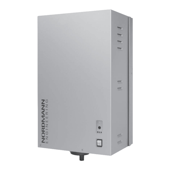
- Page 1 NORDMANN E N G I N E E R I N G Nordmann ES4 Steam air humidifier INSTALLATION- AND OPERATING INSTRUCTIONS 2559439 EN 1310...
-
Page 3: Table Of Contents
Common steam and condensate line errors 5.4.7 Inspecting the steam installation Water installation 5.5.1 Overview water installation 5.5.2 Notes on water installation 5.5.3 Inspecting the water installation Electric installation 5.6.1 Wiring diagram Nordmann ES4 5.6.2 Notes on electric installation 5.6.3 Unit configuration 5.6.4 Inspecting the electrical installation... -
Page 4: Introduction
The steam humidifier Nordmann ES4 incorporates the latest technical ad van ces and meets all recognized safety standards. Nevertheless, improper use of the Nordmann ES4 may result in danger to the user or third parties and/or impairment of material assets. - Page 5 If the equipment changes hands, the documentation should be passed on to the new operator. If the documentation gets mislaid, please contact your Nordmann supplier. Language versions The present installation and operating instructions are available in various languages.
-
Page 6: For Your Safety
It is assumed that all persons working with the Nordmann ES4 are familiar and comply with the appropriate regulations on work safety and the preven- tion of accidents. - Page 7 Touching live parts may cause severe injury or danger to life. Prevention: Before carrying out any work set the Nordmann ES4 out of operation as described in chapter 6.5 (switch off the unit, disconnect it from the mains and stop the water supply) and secure the unit against inadvertent powerup.
-
Page 8: Product Overview
Product Overview Models overview Steam air humidifiers Nordmann ES4 are available with different heating voltages and steam capacities ranging from 5 kg/h up to a max. of 65 kg/h. Heating voltage ** Max. steam capacity Model Unit size in kg/h... -
Page 9: Identification Of The Unit
3.2 Identification of the unit The identification of the unit is found on the type plate: type designation Serial number (7 digits) Month/Year Nordmann Engineering AG, CH-8808 Pfäffikon Heating voltage Type: ES4 4564 Ser.Nr.: XXXXXXX 02.10 Heating voltage: 400V / 3~ / 50...60Hz Power: 33.8 kW... -
Page 10: Steam Humidifier Construction
Terminals heating voltage (option) Water supply connector Remote operating and fault drain connector indication board (option) Cable openings, bottom side Control board with ES4 Card Type plate Steam cylinder Power supply unit 24 V (option) drain/info key Level sensor operation status indicators... -
Page 11: Functional Description
Functional description The steam humidifier Nordmann ES4 is a pressureless steam generator that utilizes an electrode heating. The steam humidifier Nordmann ES4 is designed for air humidification via a steam distributor (steam distribution pipe, fan unit or steam distribution system MultiPipe). - Page 12 Upon reaching the requested steam capacity, the inlet valve closes. If the steam generation decreases below a certain percentage of the required capacity, due to lowering of the water level (e.g. because of the evapora- tion process or drainage), the inlet valve opens until the required capacity is available again.
-
Page 13: Humidification System Overview
3.5 Humidification system overview System overview duct humidification MultiPipe DV41 DV71 DS22 DS35 KS10 Z261 125...1250 µS/cm 1...10 bar 1...40 °C 1 Steam humidifier 9 Water drain hose (included in the delivery) 2 Steam connector 10 Service switch control voltage supply (building side) 3 Water drain connector 11 Service switch heating voltage supply (building side) 4 Water supply connector 12 Steam hose (accessory “DS..”) 5 Water connection hose G 3/4"- G 3/8" 13 Condensate hose (accessory “KS10”) (included in the delivery) 14 Steam distribution pipe (accessory “DV41-..”/“DV71-..”) 6 Filter valve (accessory “Z261”) 15 Steam distribution system (accessory “MultiPipe”) 7 Manometer (installation recommended) 16 Humidity controller 0-10V or Humidistat... - Page 14 System overview room humidification FAN4 N S W FAN4 N M W FAN4 N L W DS80 KS10 Z261 125...1250 µs/cm 1...10 bar 1...40 °c Steam humidifier Water drain hose (included in the delivery) steam connector Service switch control voltage supply (building side) Water drain connector Service switch heating voltage supply (building side) Water supply connector...
-
Page 15: Options
The SC pump keeps the solved minerals in the water of the steam cylinder in motion, in order to discharge them with the automatic drain cycles. 24 VDC power supply 1x24VDC 24 VDC power supply for the external humidity sensor Nordmann ES4... (400 V/3~/50...60 Hz) 1534 2364 3264 4564 6564 Steam cylinder for low water conductivity from 80 to 125 µS/cm... -
Page 16: Accessories
Accessories 3.7.1 Accessories overview Accessories for water installation Nordmann ES4... 1532 2362 3262 4564 6564 1534 2364 3264 Filter valve Z261 (1 pcs. per system) Accessories for steam installation Nordmann ES4... 1532 2362 3262 4564 6564 1534 2364 3264 Steam distribution pipe 1xDV41-... -
Page 17: Accessory Details
Note: If the humidification distance (see chapter 5.4.2) has to be reduced for technical reasons, the amount of steam per basic unit must be divided between two steam distribution pipes or the steam distribution system MultiPipe must be used. If this is the case, contact your Nordmann supplier. - Page 18 3.7.2.2 MultiPipe steam distribution system the MultiPipe steam distribution system is used in ventilation ducts with a short humidification distance (for the calculation of the humidification dis- tance refer to chapter 5.4.2). When ordering an MultiPipe system the duct dimension must be specified. Please consult the data in the following table. MultiPipe Number of steam Max.
- Page 19 Fan units FAN4 N... The fan units FAN4 N... – in combination with the steam humidifiers Nor- dmann ES4 – are used for direct room humidification. they are mounted above the unit to the wall. the type of fan unit is dependent on the steam capacity and on the type of the humidifier and can be gathered from the table in chapter 3.7.1.
-
Page 20: Standard Delivery
Packaging Keep the original packaging of the Nordmann ES4 for later use. In case you wish to dispose of the packaging, observe the local regulations on waste disposal. Never dispose of the packaging to the environment. -
Page 21: Notes For The Planning Engineer
The total amount of losses depends on the entire system and must be taken into consideration when calculating the required steam capac- ity. If you have any questions regarding the calculation of the steam capacity please contact your Nordmann supplier. – For systems where the max. required steam capacity varies extensively (e.g. -
Page 22: Selecting The Unit
4.1.2 Selecting the unit Nordmann ES4 4564 400V3 Model Unit size Heating voltage ** Max. steam capacity Nordmann ES4 .. in kg/h Unit small Unit large 1534 400V3 2364 (400 V/3~/50...60 Hz) 3264 4564 6564 400V2 (400 V/2~/50...60 Hz) 230V3 1532 (230 V/3~/50...60 Hz) -
Page 23: Selecting The Control System
1 is suited for direct room humidification and air condition- ing systems with mainly recirculated air. the humidity sensor or humidistat respectively is preferably located in the room itself or in the exhaust air duct. nordmann humidity sensor ventilation interlock airflow monitor... - Page 24 — system 3 Direct room humidification system 1 — Please contact your Nordmann supplier, if your application meets the following conditions: – Humidification of small rooms up to 200 m – Air conditioning systems with a high number of air exchanges –...
-
Page 25: Mounting And Installation Work
Mounting and installation work Important notes for mounting and installation work Qualification of personnel All mounting and installation work must be carried out only by well quali- fied personnel authorised by the owner. It is the owner’s responsibility to verify proper qualification of the personnel. General note Strictly observe and comply with all information given in the present instal- lation and operating instructions regarding the location of the unit and the... -
Page 26: Installation Overviews
Installation overviews Installation overview duct humidification External safety chain L1 N SC1SC2 A1 / A2 ext. max. Continuous control 0-10V On/Off-Control DV41 On/Off Mode On/Off Mode CONT.SIGN CONT.SIGN DV71 V+ IN GND V+ IN GND ext. ext. Pmax 1500 Pa min. - Page 27 Installation overview room humidification External safety chain L1 N SC1SC2 ext. max. Continuous control 0-10V On/Off-Control On/Off Mode On/Off Mode CONT.SIGN CONT.SIGN FAN4 N S W V+ IN GND V+ IN GND Steam installation FAN4 N M W see chapter 5.4 ext.
-
Page 28: Mounting The Unit
60...70 °C 1 ... 40 °C max. 75 %rh IP20 1532 2362 3262 4564 6564 1534 2364 3264 Nordmann ES4 ... dimensions Housing (XxYxZ) in mm 377x279x612 492x351x670 Weights Net weight in kg Operating weight in kg... - Page 29 CAUTION! If for some reason the Nordmann ES4 must be installed in a location without floor drain, it is mandatory to provide a leakage monitoring device to safely interrupt the water supply in case of leakage.
-
Page 30: Mounting The Humidifier
5.3.2 Mounting the humidifier Dimension Housing size small large 189 mm 246 mm 61 mm 52 mm 490 mm 547 mm 120 mm 180 mm 120 mm 180 mm Procedure 1. Mark the attachment point “A” on the wall. 2. Drill hole for attachment point “A” (diameter: 8 mm, depth: 40 mm). 3. -
Page 31: Inspecting The Installed Unit
5.3.3 Inspecting the installed unit Check the following points: Is the unit installed in the correct place (see chapter 5.3.1)? Is the supporting surface stable enough? Is the unit correctly aligned, vertically and horizontally? Is the unit properly secured (see chapter 5.3.2)? Has the front panel of the unit been relocated and correctly fixed with the two screws? -
Page 32: Steam Installation
Steam installation 5.4.1 Overview steam installation DV41 DV71 Pmax 1500 Pa min. 5 % – Pmin -800 Pa DS22 DS35 min. 20 % min. 20 % – KS10 FAN4 N S W FAN4 N M W FAN4 N L W min. -
Page 33: Positioning And Mounting Of The Steam Distribution Pipes
5.4.2 Positioning and mounting of the steam distribution pipes The location for the steam distribution pipes should be determined at the time of dimensioning the air conditioning system. Please note the following instructions to ensure proper humidification of the duct air. Calculating the humidification distance The water vapour, emitting from the steam distribution pipes, requires a certain distance to be absorbed by the ambient air so that it is no longer... - Page 34 MultiPipe must be used. If this is the case, contact your Nordmann supplier. Minimum distances to be observed To prevent the water vapour, that is emitting from the steam distribution pipe,...
- Page 35 before diffuser before control sensor before/after filter/register before/after fan, zone exit 1 . 5 * 2,5 x B before aerosol filter Installation notes and dimensions The steam distribution pipes are designed for either horizontal installation (on the duct wall) or, with accessories, for vertical installation (in the duct floor).
- Page 36 – Steam distribution pipes must not be mounted to round ducts. If you have questions relating to the dimensioning of ventilation ducts in combination with steam humidifiers Nordmann ES4, contact your Nordmann supplier.
-
Page 37: Installing The Steam Distributors
5.4.3 Installing the steam distributors Detailed information on the installation of steam distribution pipes DV41 .., DV71... and MultiPipe steam distribution system can be found in the separate mounting instructions for these products. -
Page 38: Positioning And Mounting Of The Fan Units Fan4 N
Fan4 n..If you have questions concerning the direct room humidification, please contact your Nordmann supplier. Further information is provided in the separate installation and operating instructions for the fan unit. -
Page 39: Installing The Steam Hose
5.4.5 Installing the steam hose Important! Use original steam and condesate hose from your Nordmann supplier exclusively. Other types of hoses can cause undesired operational malfunctions. Instructions for the hose layout The hose layout depends on the position of the steam distribution pipe: –... - Page 40 – Steam distribution pipe is mounted less than 500 mm above the top edge of the humidifier: min. 5 % – min. 20 % min. 20 % – Obstacle min. 20 % min. 20 % min. 5 % – min. 20 % min.
- Page 41 100 Pa) per meter steam hose. Note: If your particular installation exceeds the maximum steam hose length of 4 m contact your Nordmann representative. In any case, steam hoses longer than 4 m must be insulated in their entire length (e.g.
- Page 42 Steam line with fixed piping For steam lines with fixed piping, the same instructions apply to the laying of the piping as already described. min. 20 % min. 20 % – Ømin. 200 mm The following additional notes should be observed: –...
-
Page 43: Common Steam And Condensate Line Errors
5.4.6 Common steam and condensate line errors 1. Steam hose not led at least 300 mm perpendicularly upwards before first bend. 2. Minimum bend radius of steam hose of 300 mm not maintained (forming of condesate). 3. Siphon of the condensate hose not at least 300 mm below the steam distribution pipe. -
Page 44: Inspecting The Steam Installation
5.4.7 Inspecting the steam installation Use the following check list to ascertain that the steam installation was performed correctly: – Steam distribution pipe Steam distributors (steam distribution pipe or MultiPipe steam distri- bution system) correctly positioned and secured (screws tightened)? Are the outlet orifices at right angles to the air flow direction? –... -
Page 45: Water Installation
Water installation 5.5.1 Overview water installation G 3/4" ø 30 mm G 3/4" ø 30 mm G 3/4" ø14/7 mm ø14/7 mm G 1/2" ø 40/31 mm G 3/8" G 3/8" Z261 125...1250 µS/cm ≥ 40 mm 1...10 bar 1...40 °C... -
Page 46: Notes On Water Installation
– If the Nordmann ES4 shall be operated with softened or partly sof- tened water, please contact your Nordmann supplier. – The connection material must be pressure-proof and certified for use in drinking water systems. -
Page 47: Inspecting The Water Installation
5.5.3 Inspecting the water installation Check the following topics: – Water supply Has filter valve (accessory “Z261”) or shutoff valve and 5 µm water filter respectively been installed in supply line? Have admissible water pressure (1 – 10 bar) and admissible tem- perature (1 –... -
Page 48: Electric Installation
Electric installation 5.6.1 Wiring diagram Nordmann ES4 Control board Power board Driver board L1 L2 L3 ES4 Card CURRENT SENSOR LEV.SENSOR Drain Factor L1 L2 L3 Cylinder Power Limit ext. Settings CPU BOARD Manual Drain Low Conduct. (6.3 AT) Standby Drain... -
Page 49: Notes On Electric Installation
Before connecting, ensure that the mains voltage corresponds with the heating voltage for the unit (see type plate). The Nordmann ES4 is to be connected to the mains supply in accordance with the wiring diagram, via a service switch “Q2” (disconnecting device with a minimum contact opening of 3 mm is an essential requirement) and an fuse group “F2”... - Page 50 Control voltage supply CAUTION! – Before connecting, ensure that the mains voltage corresponds with the control voltage of the unit (230 V/1 50…60 Hz). – The humidifier must only be connected to a mains supply with a protective conductor. the connection to the control voltage is made in accordance with the wir- ing diagram, to the terminal “X3”...
- Page 51 Remote operating and fault indication H1 (Option “RFI”) The optional remote operating and fault indication PCB is to be connected to the control board via the terminal “J1”. The optional remote operating and fault indication PCB contains four potentialfree relay contacts for the connection of the following operating and fault indications: –...
-
Page 52: Unit Configuration
(setting range: 30...100%, factory setting: 100%). General settings (“Settings”) With the DIP switches “Settings” you can set different unit parameters. The unit parameters are preset in the factory and may only be modified by the client after consulting the Nordmann representative. Switch Factory setting Description ON: low water conductivity <125 µS/cm... -
Page 53: Inspecting The Electrical Installation
Do the supply voltages for heating and control comply with the relevant voltages given in the wiring diagram? Is the correct ES4 Card inserted? Are the voltage supplies (heating and control voltage) correctly fused? Is the service switch “Q..” installed in the supply line for to the heating... -
Page 54: Operation
Operation Function of the display and operating elements Drain/Info key press key shortly: Opens and closes the drain valve (manual drain- – ing). Note: the drain valve is automatically closed after 10 minutes. press key for a extended period of time (>3 sec.): activating the –... -
Page 55: Commissioning
LED lights up and after a few minutes (approx. 5–10 minutes, depending on the conductivity of the water) steam is produced. Note: If the Nordmann ES4 is operated with water of low conductivity it may happen that the maximum steam capacity is not reached in the first few hours of operation. -
Page 56: Notes On Operation
Notes on operation 6.3.1 Function of the LED's in info mode The info mode is activated by pressing the drain/info key for an extended period of time (> 3 seconds). After activating the info mode: – first, the green LED flashes. The number of flashes indicates the current steam output in % of the maximum steam capacity. -
Page 57: Carrying Out Manual Draining
If the inspection reveals any irregularities (e.g. leakage, error indication) or any damaged components take the nordmann es4 out of operation as described in chapter 6.5. Then, contact your Nordmann representative. Carrying out manual draining Proceed as follows to drain the unit manually: 1. -
Page 58: Maintenance
Prevention: Before carrying out any maintenance work set the Nordmann ES4 out of operation as described in chapter 6.5 (switch off the unit, dis- connect it from the mains and stop the water supply) and secure the unit against inadvertent powerup. -
Page 59: Maintenance List
Maintenance list To maintain operational safety the Nordmann ES4 steam humidifier must be maintained at regular intervals. This is differentiated between the first maintenance after approx. 500 operating hours (I), steam cylinder re- placement after the yellow LED lights (II) and annual maintenance (III). -
Page 60: Removing And Installing Parts For Maintenance
Removing and installing parts for maintenance 7.3.1 Removal and installation of the steam cylinder 1. Undo the two screws fixing the front panel to the unit using a screwdriver, then remove the front panel. 2. Release the hose clamp on the steam hose using a screwdriver, then detach the steam hose from the steam outlet connection of the steam cylinder. - Page 61 5. Carefully lift steam cylinder away from the cylinder receptacle, then remove it to the front. CAUTION! Put steam cylinder down carefully to avoid damage to the lower con- nection piece! 6. Carefully pull the drain screen out of the drain outlet of the steam cylinder. Note: this step must only be carried out if the drain screen is clogged (see chapter 8.2.2 “Unit faults”) and the steam cylinder can still be used.
- Page 62 Installation of the steam cylinder follows the reverse sequence. Observe the following: – Before installing the steam cylinder in the unit, check the Oring of the cylinder receptacle for damage and replace if necessary. – Moisten the Oring of the cylinder receptacle with water (do not use grease or oil), then insert steam cylinder into the receptacle and push it down to the stop.
- Page 63 7.3.2 Removal and installation of the drain cup 1. Release the hose clamp, then remove water drain hose from the con- nector on the water cup. 2. Undo the three screws fixing the drain cup to the unit using a screwdriver, then remove the drain cup downwards.
-
Page 64: Removal And Installation Of The Water Cup And The Water Hoses
7.3.3 Removal and installation of the water cup and the water hoses For removing the water cup and the water hoses the steam cylinder must be removed first (see chapter 7.3.1). 1. Release hose clamps using pliers, then disconnect all hoses from the corresponding connectors and remove the hoses. -
Page 65: Removal And Installation Of The Drain Valve
7.3.4 Removal and installation of the drain valve For removing the drain valve the steam cylinder must be removed first (see chapter 7.3.1). 1. Detach electric cables (polarity of the cables must not be observed). 2. Release hose clamp and remove the hose from the connector. 3. -
Page 66: Removal And Installation Of The Inlet Valve
7.3.5 Removal and installation of the inlet valve For removing the inlet valve the steam cylinder must be removed first (see chapter 7.3.1). 1. Detach electric cables (polarity of the cables must not be observed). 2. Release hose clamp and remove the hose from the connector. 3. -
Page 67: Notes On Cleaning The Unit Components
Notes on cleaning the unit components Unit component What to clean and how to clean Water hoses • Remove any limescale by slightly knocking on the tubes using a rubber hammer. Then, rinse the tubes well with hot tap water. Inlet valve •... -
Page 68: Notes On Cleaning Agents
Unit component What to clean and how to clean Drain cup • Use a brush to remove any limscale from the drain cup and the receptacle on the bottom side of the unit (do not use a wire brush). If the drain cup is heavily calcified, place it in an 8% formic acid solution (observe safety notes in chapter 7.5), until the limescale comes off. -
Page 69: Fault Elimination
Fault elimination Important! Most operational malfunctions are not caused by faulty equipment but rather by improper installation or disregarding of planning guidelines. Therefore, a complete fault diagnosis always involves a thorough examina- tion of the entire system. Often, the steam hose connection has not been properly executed, or the fault lies with the humidity control system. -
Page 70: Malfunction Lists
Warning Error Cause Remedy Code Malfunction Code Malfunction ES4 Card missing No ES4 Card installed on the con- Install ES4 Card or start test run. trol board. ––– ––– ES4 Card is empty no data stored on the es4 card. - Page 71 Warning Error Cause Remedy Code Malfunction Code Malfunction No electrode current No electrode cur- Phase failure heating voltage. Inspect/turn on service switch of for more than 20 rent for more than the mains supply line. Inspect the minutes 4 hours fuses of the mains supply, replace if necessary.
-
Page 72: Notes On Fault Elimination
The elimination of faults must be carried out by qualified and well trained professionals only. Malfunctions relating to the electrical installation (e.g. replacement of fuses) must be repaired by authorized personnel or by your Nordmann representa- tive’s service technician only. Repair work and the replacement of faulty components must be carried out by your Nordmann representative’s service technician only! -
Page 73: Taking Out Of Service/Disposal
Taking out of service/Disposal Taking out of service If the Nordmann ES4 must be replaced or if the humidification system is not needed any more, proceed as follows: 1. Take the unit out of operation as described in chapter 6.5. -
Page 74: Product Specifications
Product specifications 10.1 Technical data Steam capacity in kg/h Capacity range in kg/h 1...5 1.6...8 3...15 4,6...23 6,4...32 9...45 13...65 Nominal power in kW 11,3 17,3 24,0 33,8 48,8 Heating voltage 230V/1~/50..60Hz * Unit model Nominal current in A 16,3 26,1 Steam cylinder type ** 522A 822A Heating voltage 400V/2~/50..60Hz *... -
Page 75: Unit Dimensions
10.2 Unit dimensions Nordmann ES4 5/8/15 (dimensions in mm) 120 120 ø30... - Page 76 Nordmann ES4 23/32/45/65 (Dimensions in mm) ø30...
- Page 77 Notes...
- Page 78 Notes...
- Page 79 © Nordmann Engineering Ltd., Printed in Switzerland Technical modifications reserved...
- Page 80 Dampfluftbefeuchter E N G I N E E R I Reg.No. 40002-2 Manufacturer: Nordmann Engineering Ltd. NORDMANN Talstrasse 35-37, 8808 Pfäffikon, Switzerland Ph. +41 55 416 66 06, Fax +41 55 416 62 46 E N G I N E E R I N G...
Need help?
Do you have a question about the ES4 and is the answer not in the manual?
Questions and answers