Table of Contents
Advertisement
Advertisement
Table of Contents

Related Manuals for Nordmann AT 3000 series


Summary of Contents for Nordmann AT 3000 series
-
Page 1: Operating Instructions
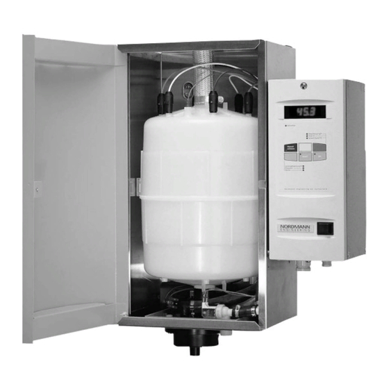
Operating instructions NORDMANN Steam humidifiers of the AT 3000 series ● Installation ● Connecting the water and the electrics E N G I N E E R I N G ● Putting into operation ● Servicing and system signals ●... -
Page 2: Table Of Contents
Introduction You have purchased a NORDMANN steam humidifier which, provided you observe the operating instructions, will ensure fully automatic operation and reliable, low-maintenance service. Therefore, read these operating instructions carefully and pay particular attention to the safety instructions and warnings. -
Page 3: Installation
The user shall bear the risk. Alterations to the humidifier Without NORDMANN’s written approval, no alterations may be made to the humidifier itself, the components or the accessories. The use of non-original spare parts may lead to our refusal to accept responsibility for any damage arising therefrom. - Page 4 Tiefe Breite Fig. 1 Fig. 2 Fixing holes for type 64, 90 130 kg/h (mm) Fixing holes for type 4-65 kg/h Type (mm) (mm) 4 - 8 kg 15-23 kg 32-65 kg 4 holes required for humidifiers of 15 kg and above 3 holes required for humidifiers of 4 and 8 kg/h...
- Page 5 Fig. 5 Fig. 6 Dimensions of the Fig. Type 4-23 kg/h steam blowers 4 - 8 kg/h Ø 22 Ø 8 15-23 kg/h Ø 35 Ø 8 Dimensions of the 4-23 kg/h steam blowers Fixing holes for 4-23 kg/h Type 4-8 kg/h Type 15-23 kg/h steam blowers Type...
-
Page 6: Steam Nozzle
An adhesive template is supplied with each steam-distribution pipe to facilitate installation in, for instance, an air duct. NORDMANN’s steam-distribution pipes are designed so that, if fitted straight, there is automatically a slight decline of 3% which ensures that any condensate flows back again. - Page 7 Guidelines on fitting the steam-distribution pipes min 300 Fig. 14 Various fitting methods Fig. 15 A = min. 200 Fig. 16 A = min. 250 Fig. 17 A > 300 B = min. 150 B = 0.5 A Fig. 18 A >...
-
Page 8: Fitting The Steam Blowers
1.5 Fitting the steam blowers All installation work must be performed by trained personnel. The customer himself is responsible for verifying their qualifications. The steam blower for distributing the steam in the room can be fitted either directly onto the humidifier itself (excepting types 32 to 130 kg/h) or onto a wall. -
Page 9: Laying The Steam Hose
Installation material If a hose is used for the steam line, it must be the original one supplied by NORDMANN. If other hoses are utilised, NORDMANN cannot be held responsible for any damage that may occur. A hose clamp should be used to link the hose to the steam-distribution pipe. -
Page 10: Laying The Condensate Hose
1°DH = 17.9 mg/l CaCO 3 (ppm) NORDMANN’s electrode steam humidifiers allow you to use water ranging from soft to very hard, without the need for prior treatment. However, for fairly hard water and above, we recommend the use of the SC-System (NORDMANN’s self-cleaning system), since this greatly reduces the amount of maintenance required for the cylinder. -
Page 11: Electrical Connections
The installation must be fitted with a device which disconnects the unit (with a contact opening of at least 3 mm) on all phases from the mains power supply. NORDMANN humidifiers are designed to be connected to the earth lead and are categorised as belonging to Protection class 1 for electrical equipment. -
Page 12: Proportional Adaptor (Option)
The use of fuzzy logic technology improves the controllability. The microcontroller of the AT 3000 series works with fuzzy-logic algorithms. This regulates the conductivity or mineral concentration in the steam cylinder and achieves ideal operating conditions while, at the same time, maximising the operational reliability. -
Page 13: The Steam Cylinder And The Sc-System
We recommend that you keep a spare cylinder in stock for each unit. NORDMANN’s steam cylinders are so economical that it is usually cheaper to replace the cylinder than to clean it. To clean the cylinder, it should first be emptied (by pressing the button for manual draining) and then removed. -
Page 14: Putting The Humidifier Into Operation
4.5 Programming level The humidifiers of the AT 3000 series have a programming level which has a large array of functions, allowing the unit’s characteristics to be matched to a wide variety of conditions or tailored exactly to the customer’s particular requirements. -
Page 15: Information From The Display
4.7 Information from the display The large-scale, four-digit, LED display allows numbers and letters to be indicated. Its size and clarity mean that it can be read easily even when the light is poor. Function Allows the steam cylinder to be manually drained. Pressing T1 once causes the drainage valve to open. -
Page 16: Servicing And System Messages
4.8 Servicing and system messages The newly-developed electronic controls unit with microcontroller continuously monitors the operations of the AT 3000 humidifiers. Any deviations from the operating condition (U codes) are shown on the display. Code U1 Servicing signal The steam cylinder can no longer attain the nominal output and needs, therefore, to be cleaned or perhaps replaced. A visual inspection of the inside of the cylinder is necessary to be able to decide whether it needs replacing. -
Page 17: Drainage Strainer In The Steam Cylinder
Fig. 35 5.2 Drainage strainer in the steam cylinder All NORDMANN steam cylinders are fitted with a removable drainage strainer which can be extracted easily for cleaning. The drainage strainer and the cylinder can then be put back into place and the humidifier put back into operation. -
Page 18: Regular Servicing
5.5 Regular servicing Regular servicing helps to maintain the operability and reliability of the humidifier. All work must be carried out by qualified personnel only. The customer is responsible for verifying the qualifications of the technicians concerned. Before commencing work, all power to the humidifier must be switched off. The following checks should be carried out on a regular basis: •... - Page 19 Starting the service program ☞ • Key T4 Select the servicing level ☞ • Key T5 (SELECT) To select the checking operations ☞ • Key T6 (SET) To select either 1 (active) or 0 (inactive), or to switch components on or off N.B.: On double units (two cylinders), first choose the appropriate cylinder by pressing key 2.
-
Page 20: Integrated Humidity Controller
5.7 Integrated Humidity Controller 5.7.1 Function The integrated humidity controller is a new feature for all AT 3000 units with software version XP 16B or higher. This newly designed and programmable function enables the humidity in the duct or in the ambient to be controlled. For connecting a humidity sensor to the integrated humidity controller the proportional adaptor (Art. -
Page 21: Rectifying Faults
5.7.4 Maximum Level Hygrostat (safety device) Basically a simple on/off hygrostat is used as a maximum hygrostat. As usual it is connected to the safety circuit (terminals L1 + H). Please also refer to the wiring diagram of the AT 3000 unit. 5.7.5 Humidity sensors with double units The two cylinders of a double unit either can be run together (in parallel) or controlled separately from each other. -
Page 22: Spare Parts List
7. Spare parts list Detailed drawings of spare parts with their article number are available from your NORDMANN representative. 8. List of options All options can be fitted either at the factory or subsequently. Remote indication Three selective remote-indication relays with potential-free change-over contacts, max. 250 V, 2 A. -
Page 23: Technical Specifications
9. Technical specifications Type mark Type 1534 2364 3264 4564 6464 6564 9064 13064 Heating voltage 400 V, 50/60 Hz Number of phases Heating current 15.2 16.5 25.2 35.1 49.4 2 x 35.1 71.3 2 x 49.4 2 x 71.3 External fuses p. - Page 24 Manufacturer: Nordmann Engineering AG P.O. Box, CH-4143 Dornach 1 / Switzerland Bruggfeldweg 11, CH-4147 Aesch / Switzerland Tel. +41 61 467 76 66 Fax +41 61 467 76 77 E-mail: info@nordmann-engineering.com Internet: www.nordmann-engineering.com NORDMANN E N G I N E E R I N G...
Need help?
Do you have a question about the AT 3000 series and is the answer not in the manual?
Questions and answers