
Related Manuals for HYBREX GDS-600


Summary of Contents for HYBREX GDS-600
- Page 1 The Business Telephone Specialists GDS-600 Digital Telephone System ISDN Digital Telephone System Installation Manual V4.1.1...
-
Page 2: Notification
Notification Notification is hereby given that Auto Telecom Company Ltd. reserves the right to modify, change, update or revise this document from time to time as required without the prior obligation to notify any person, company or organization. Further, Auto Telecom makes no warranty or representation, either express or implied, with respect to merchantability, or fitness of its products for a particular purpose. -
Page 3: Important Safety Instructions
4. Use caution when installing or modifying telephone lines. The HYBREX GDS-600 utilizes a 3 pin grounding power supply cord. This cord is not to be attached to any building surfaces. When using your telephone equipment, basic safety precautions should always be followed to reduce the risk of fire, electric shock and injury to persons, including the following: 1. -
Page 4: Table Of Contents
ERMINAL QUIPMENT ............................1 ADIO REQUENCY NTERFERENCE CTR 21 (98/482/EC) DECLARATION NETWORK COMPATIBILITY ................1 ISDN INSTALLATION ................................1 KEY HIGHLIGHTS OF THE GDS-600 SERIES INCLUDE: .................... 3 ..............................3 CONOMY AND FFICIENCY ................................3 NSTALLATION ................................3 AINTENANCE ..........................3... - Page 5 G2-MBU – 40 ................................16 PORTS G2-MBU - 64 P ................................17 ORTS G2-MBU – 80 P ................................18 ORTS G2-MPU2 ....................................19 G2-MPUN2 ..................................... 20 G2-MPU4 ....................................21 G2-MXU4 ....................................22 G2-MPUN4 ..................................... 23 G2-MXUN4 .................................... 24 G2-MPU8 ....................................25 G2-MXU8 ....................................
- Page 6 ................................64 PERATIONAL ESTS SPECIAL IMMUNITY PROTECTION FOR SYSTEM AND TERMINALS..............64 GDS-600 POWER CONSUMPTION CALCULATION FOR EMERGENCY BATTERY BACKUP ......66 APPENDIX A ..................................68 MPU SOFTWARE UPGRADE ............................68 APPENDIX B ..................................74 PC UPGRADE PROCESS FOR GDS IPU ......................... 74...
-
Page 7: General Description - Introduction
In the event of problem, you should contact your equipment supplier in the first instance.’ ISDN Installation For the ISDN unit (G2-SIU), GDS-600 only offers ISDN S/T interface connection behind an NT1 device. It can not be connected to a “U” interface directly. - Page 8 Description The GDS-600 is an advanced ISDN Digital hybrid telephone system employing a microprocessor stored program and digitally controlled solid state Time-division switching. The GDS-600 system is specifically designed for small business as well as residential applications. At the forefront of the system design is a universal concept to adapting and connecting with a variety of communications devices.
-
Page 9: Key Highlights Of The Gds-600 Series Include
This allows a wide variety of applications for the system to work effectively. Easy Installation “Factory Ready” - All GDS-600 Telephone systems are "ready to go" right out of the box. A well thought out default database is factory installed on each system which meets the needs for most installations. This alleviates hours of on site time, minimizing installation costs for both dealer and customer. -
Page 10: Full Isdn Features
Full ISDN features The GDS 600 system allows you to access different outside line types (PSTN, VOIP & ISDN BRI, PRI, T1, E1, …) in one box and enjoy Full ISDN Features when accessing an ISDN Line - such as: Call Charge Metering Information Caller Identification Direct Inward Dialing... - Page 11 GDS-600 - General Description HYBREX Telephone Models DK1-21/DK1-31 (Obsolete) ACP Plastic (obsolete) ACP Steel DK-DPU1 (Obsolete) ACP40 ACP30 DK2-21 DK2-21 + DK2-DSS DK3-33 DK3-21...
- Page 12 DK6-21 DK6-31 DK6-33 DK7-21 IP-38-61 DK9-25 DK9-15 DK9-DSS Issue 4.1.1 - October 2014...
-
Page 13: Mechanical Specifications - Key Service Unit - Single Cabinet
GDS-600 - General Description MAXIMUM LOOP RESISTANCE/IMPEDANCE Key Telephone 26 AWG / 200 m 24 AWG / 300 m Single Line telephone 26 AWG / 1000 m 22 AWG / 3000 m Doorphone Less than 40 ohms Music Source Input Impedance... -
Page 14: Features
Features System Features Account Code Capability ISDN Attendant Console Assignment Call Charge Metering Information Attendant Overflow Caller Identification Automatic Line Access Direct Inward Dialing Automatic Line Search Call Forward Internal / External Automatic Ringdown Call Waiting Automatic Wake-up MSN (Multiple Subscriber Number) Battery Charger Sub-addressing Behind PABX Operation... -
Page 15: Station Features
GDS-600 - General Description Station Features On Hook Dialing Prime Line Select Advisory Messages Privacy System Privacy Release Personal Private Line Access to System Programming Pulse/Tone Conversion Account Code Capability Ring Frequency Selection Auto Hold Ringing Line Preference Auto Hold Recall... -
Page 16: Parts & Peripherals
Parts & Peripherals System Modules Model Description G2-MMD160 Master Device 80 port Cabinet for 160 ports including: 80 port cabinet x 1, MBU, PWU, MPU2, IPU, MSU, IXU G2-MMD320 Master Device 80 port Cabinet for 320 ports including: 80 port cabinet x 1, MBU, PWU, MPU4, MXU4, IPU, MSU, IXU G2-MMD640 Master Device 80 port Cabinet for 640 ports including: 80 port cabinet x 1, MBU, PWU, MPU8, MXU8, IPU, MSU, IXU... -
Page 17: Optional Interface Cards
GDS-600 – System Installation Optional Interface Cards Model Description G2-VMU Voice Mail Unit (4 Channels) / Auto Attendant / Wake-up / Message Waiting Caller ID Card for G2-TKU – Dual Mode (FSK/DTMF) G2-CIC Caller ID Card for G2-TKU – FSK Mode... -
Page 18: System Installation - Introduction
G2-CIC Card (Caller ID Card - four port circuits) Voice Mail Unit (G2-VMU) Metering Card (G1-MDC) NOTE: Please follow the directions step by step. The GDS-600 system should be installed in strict accordance with this manual. Issue 4.1.1 - October 2014... -
Page 19: Site Requirements
GDS-600 – System Installation Site Requirements Location Choosing the Right Environment System should be installed in a clean, dry, secure location. This location must have adequate ventilation, and a temperature from 0 ℃ to 45℃ (32℉ to 113℉), with 10% to 95% non-condensing relative humidity. DO NOT install the equipment near sources of static electricity, excessive vibration, or water. -
Page 20: Installing The Equipment
Installation Caution 1. This system should be installed by qualified service personnel. 2. Do not install the Power Supply unless you have read the following instructions and completed all the installation and wiring. 3. STATIC SENSITIVE DEVICES! Please handle with care. Installing the Equipment Backboard Be sure to plan and allow enough space to mount and... -
Page 21: Installing Expansion And Optional Cards
GDS-600 – System Installation Installing expansion and optional cards In this step you will be installing printed circuit cards on to slots of the main board in the basic cabinet. Take your time and extra care to assure the printed circuit cards are properly aligned. After installing each option and expansion card, perform a visual inspection to assure the printed circuit card is installed properly. -
Page 22: Card Introduction
Card Introduction G2-MBU – 40 ports 1.) Power socket to connect to the main power unit (G1-PWU) 2.) Fan power input (3-PIN) 3.) G2-MPU2/G2-MPU4/G2-MPU8 slot 4.) LED1: Power LED of system (Steady on when power is ON) 5.) JP1: Reset jumper for flash memory 6.) VMU slot 7.) TKU Slot 2/3 setting Jumper 8.) MSU slot... -
Page 23: G2-Mbu - 64 Ports
GDS-600 – System Installation G2-MBU - 64 Ports 1.) CN1: Power socket to connect to the main power unit (G2-PWU) 2.) Fan Input power 3.) Fan power output 4.) MPU slot 5.) Reset jumper for flash memory 6.) Cabinet position selection 7.) Power LED Solid red when power on... -
Page 24: G2-Mbu - 80 Ports
G2-MBU – 80 Ports 1.) Power socket to connect to the main power unit (G2-PWU) 2.) Fan Power Input 3.) Fan power output x 2 (3 Pin) 4.) MPU slot 5.) JP1: Reset jumper for flash memory 6.) SW1: Cabinet position selection 7.) LED 1 Power LED of system. -
Page 25: G2-Mpu2
GDS-600 – System Installation Installing CPU and option cards (continued) G2-MPU2 1. Expansion connector 1 for G2-IPU2 in the first cabinet 2. Expansion connector 2 for G2-IPU2 in the second cabinet 3. RS232 port 4. TCP/IP LAN port 5. Factory Test connector 6. -
Page 26: G2-Mpun2
G2-MPUN2 Card description of G2-MPUN2 1. Expansion connector 1 for G2-IXU/G2-IPU2 in the first cabinet 2. Expansion connector 2 for G2-IXU in the second cabinet 3. TCP/IP LAN port 4. RS232 port 5. Reset button 6. LED: Heart Bead LED4: Main Loop, normally a green light flashes slowly LED3: Heartbeat status, normally a red light flashes slowly... -
Page 27: G2-Mpu4
GDS-600 – System Installation G2-MPU4 1. TCP/IP LAN port 2. Expansion connector 1 for G2-IPU2 in the 2 cabinet 3. Expansion connector 2 for G2-IPU2 in the 3 cabinet 4. Expansion connector 3 for G2-IPU2 in the 4 cabinet 5. RS232 port 6. -
Page 28: G2-Mxu4
G2-MXU4 1. Expansion connector 1 for G2-IXU in the 1 cabinet 2. Expansion connector 2 for G2-IXU in the 2 cabinet 3. Expansion connector 3 for G2-IXU in the 3 cabinet 4. Expansion connector 4 for G2-IXU in the 4 cabinet 5. -
Page 29: G2-Mpun4
GDS-600 – System Installation G2-MPUN4 Card description of G2-MPUN4 1. TCP/IP LAN port 2. Expansion connector 1 for G2-IPU2 in the 2 cabinet 3. Expansion connector 2 for G2-IPU2 in the 3 cabinet 4. Expansion connector 3 for G2-IPU2 in the 4 cabinet 5. -
Page 30: G2-Mxun4
G2-MXUN4 1. Expansion connector 1 for G2-IXU in the 1 cabinet 2. Expansion connector 2 for G2-IXU in the 2 cabinet 3. Expansion connector 3 for G2-IXU in the 3 cabinet 4. Expansion connector 4 for G2-IXU in the 4 cabinet 8. -
Page 31: G2-Mpu8
GDS-600 – System Installation G2-MPU8 1. TCP/IP LAN port 2. Expansion connector 1 for G2-IPU2 in the 2 cabinet 3. Expansion connector 2 for G2-IPU2 in the 3 cabinet 4. Expansion connector 3 for G2-IPU2 in the 4 cabinet 5. Expansion connector 4 for G2-IPU2 in the 5 cabinet 6. -
Page 32: G2-Mxu8
G2-MXU8 1. Expansion connector 1 for G2-IXU in the 1 cabinet 2. Expansion connector 2 for G2-IXU in the 2 cabinet 3. Expansion connector 3 for G2-IXU in the 3 cabinet 4. Expansion connector 4 for G2-IXU in the 4 cabinet 5. -
Page 33: G2-Mpun8
GDS-600 – System Installation G2-MPUN8 G2-MPUN8 Card Diagram TCP/IP LAN port Expansion connector 1 for G2-IPU2 in the 2 cabinet Expansion connector 2 for G2-IPU2 in the 3 cabinet Expansion connector 3 for G2-IPU2 in the 4 cabinet Expansion connector 4 for G2-IPU2 in the 5... -
Page 34: G2-Mxun8
G2-MXUN8 Expansion connector 1 for G2-IXU in the 1 cabinet Expansion connector 2 for G2-IXU in the 2 cabinet Expansion connector 3 for G2-IXU in the 3 cabinet Expansion connector 4 for G2-IXU in the 4 cabinet Expansion connector 5 for G2-IXU in the 5 cabinet Expansion connector 6 for G2-IXU in the 6 cabinet... -
Page 35: G2-Ipu2 Intermediate Processing Unit
GDS-600 – System Installation G2-IPU2 Intermediate Processing Unit 1.) SW1: Reset button 2.) JP2: Terminators – Keep it at ‘Off’ position always(Default) 3.) HDLC controller for bus expansion of multi-cabinet. 4.) LED1: Heart beat LED 5.) CN6: connector for expanding cabinet 6.) CN5: connector for expanding cabinet 64 port only... -
Page 36: Hardware Installation
Hardware Installation A. 64 ports (16x48) + 80 ports (G2-EMD80) 1. Assume system is powered off. 2. Adjust SW1 on G2-MBU for both cabinets. For the 1 cabinet For the 2 cabinet 3. Install G2-MPU2 in the MPU/LMU slot of the 1 cabinet. - Page 37 GDS-600 – System Installation 7. Connect the expansion cable (long red one) between the G2-MPU2 and the G2-IXU in the 2 cabinet 8. Connect the expanding cable (long blue one) between the G2-IPU2 in each cabinet 9. Install all other interface cards in cabinets.
-
Page 38: Gds600 160 Ports - 80 Ports (G2-Mmd160) + 80 Ports (G2-Emd80)
B. GDS600 160 ports - 80 Ports (G2-MMD160) + 80 ports (G2-EMD80) 1. Assume system is powered off. 2. Adjust SW1 on G2-MBU for both cabinets. For the 1 cabinet For the 2 cabinet 3. Install the G2-MPU2 in the MPU/LMU slot of the 1 cabinet. - Page 39 GDS-600 – System Installation 7. Connect the expansion cable (long red one) between the G2-MPU2 and the G2-IXU in the 2 cabinet 8. Connect the expansion cable (long blue one) between the G2-IPU2s in each cabinet 9. Install all other interface cards in cabinets.
-
Page 40: Gds600 320 Ports - 80 Ports (G2-Mmd320) + 80 Ports (G2-Emd80)
C. GDS600 320 ports - 80 ports (G2-MMD320) + 80 ports (G2-EMD80) 1. Assume system is powered off. 2. Adjust SW1 on G2-MBU for all cabinets. For the 1 cabinet the 2 cabinet For the 3rd cabinet For the 4th cabinet 3. - Page 41 GDS-600 – System Installation 7. Install a G2-IXU in the IXU slot of each cabinet (G2-MMD320 and G2-EMD80). 8. Connect the expansion cable (short red 1) from the G2-MXU4 and the G2-IXU in the 1 cabinet as below. Connect the expansion cable (long red 2) from the G2-MXU4 and the G2-IXU in the 2nd cabinet as below.
-
Page 42: Gds600 640 Ports - 80 Ports (G2-Mmd640) + 80 Ports (G2-Emd80)
D. GDS600 640 ports - 80 ports (G2-MMD640) + 80 ports (G2-EMD80) 1. Assume system is powered off. 2. Adjust SW1 on G2-MBU for all cabinets. For the 1 cabinet For the 2 cabinet For the 3rd cabinet For the 4th cabinet For the 5 cabinet For the 6... - Page 43 GDS-600 – System Installation 6. Install the G2-IPU2 (HDLC chip on U17) in the IPU slot of each cabinet. Note: The G2-IPU2 is for multi-cabinet use. The G2-IPU is only for single cabinet use. 7. Install the G2-IXU in the IXU slot of each cabinet (G2-MMD640 and G2-EMD80).
- Page 44 9. Connect the expansion cable (long blue ‘2’) from the G2-MPU8 to the G2-IPU2 in the 2 cabinet. Connect the expansion cable (long blue ‘3’) from the G2-MPU8 to the G2-IPU2 in the 3 cabinet. ……………. Connect the expansion cable (long blue ‘8’) from the G2-MPU8 to the G2-IPU2 in the 4 cabinet.
-
Page 45: G2-Msu- Multi Service Card
GDS-600 – System Installation G2-MSU- Multi Service Card JP1: Grounding Jumper for specific external paging devices This is unlikely to be needed for most equipment. 1.) Grounding Jumper 2.) MODEM connector for the external MODEM connection to the system 3.) RS232 connector 4.) Relay / Sensor / External Paging connector... -
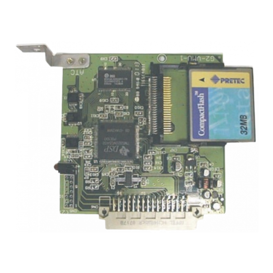
Page 46: G2-Vmu- Voice Mail Service Card
G2-VMU- Voice Mail Service Card Install the G2-VMU card in the VMU1 or VMU2 slot of the G2-MBU. G2-STU Digital Station Card Install the G2-STU card in STU1, STU/SLU2, …, STU/SLU5 slot of the G2-MBU. The STU card has 4 digital ... -
Page 47: G2-Slu Analog Station Card
Install the G2-HSU-44 card in STU/SLU2, …, STU/SLU5, SLU6 slot of the G2-MBU. G2-ASU 8 Analogue Keyphone Interface Card The G2-ASU 44 card has 8 circuits for connecting Analogue KeyPhones from the Hybrex BX range of telephone systems. The Minimum software level is G3-E050H and Wobg ... -
Page 48: G2-Tku- 4 Port Co Line Card And G2-Cic- Caller Id Card
G2-TKU- 4 Port CO Line Card and G2-CIC- Caller ID Card Install the G1-CIC card or G1-MDC card on the G2-TKU (optional). Install the G2-TKU card in TKU1/TKU2/TKU3/TKU4/(TKU5) slot of the G2-MBU. Adjust JP1 of G1-CIC card for G2 use. Install the G1-CIC card on CN6/CN7 of G2-TKU card. Mis-alignment could damage both cards or the system. -
Page 49: G2-Viu Voice Over Ip Card (Superseded)
GDS-600 – System Installation G2-VIU Voice Over IP Card (superseded) Install the G2-TKU card in the TKU1/TKU2/TKU3/TKU4/(TKU5) slots of the G2-MBU. VIU cards can be either SIP or MGCP depending on the firmware installed. G2-VMU Voice Mail Unit ... -
Page 50: G2-Ams Advanced Messaging System
G2-AMS Advanced Messaging System Legend: (1) UART pin header: Used for updating the software of the AMS card via the RS-232 port. (2) G2-ITC pin header: Used for connecting the DSP daughterboard that increases the channel-capacity. (3) Reset Button: Pressing this button will restart the AMS card. (4) WAN Port: Connection to a Switch or a Hub (5) LAN Port (6) Attached Memory Card... -
Page 51: G2-Itu Voip Sip Trunk Card
GDS-600 – System Installation G2-ITU VOIP SIP Trunk Card • The G2-ITU card is a SIP protocol (VoIP) Trunk Card • The G2-ITU card is available in 4, 8, or 16 channel versions. • It installs in any slot in a GDS system that has an extension slot connector. -
Page 52: G2-Isu Ip Extension Card
G2-ISU IP Extension Card: • The G2-ISU card is a SIP protocol (VoIP) Extension Card • The G2-ISU card is available in 4, and 8 channel versions initially. • It installs in any slot in a GDS system that has an extension slot connector. The G2-ISU8 has a daughterboard that provides more DSP processors for the extra Codec channels. -
Page 53: G2-Siu Isdn S/T Interface Card
GDS-600 – System Installation G2-SIU ISDN S/T Interface Card: Install the G2-SIU card in TKU1/SIU1 or TKU2/SIU2 slots of the G2-MBU. JP3(A,B,C): DC feeding jumper. Default is no DC output. If the internal ISDN device does not offer local power and needs DC feeding to work. -
Page 54: G2-Piu Isdn Pri / T1 / E1 Interface Card
G2-PIU ISDN PRI / T1 / E1 Interface Card Install the G2-PIU card in the TKU1/SIU1 slot of the G2-MBU. The slot immediately after the G2-PIU card must be left vacant. If the PIU card has 30 channels connected in a 64 port cabinet then the STU/SLU 1 slot must be left vacant. Which limits the Extension capacity of the 64 port cabinet to 40. - Page 55 GDS-600 – System Installation Voltage Selection Check Check to ensure the power supply jumper setting is for the proper voltage. When complete, place the power supply cover back on the power supply. Replace Fuses of Power Supply Replace Cover With the expansion and option cards installed and the battery insulator removed, replace the cover and install the 4 screws removed earlier.
- Page 56 Preparing the External Battery Backup The Key Service Unit can have two battery backup devices BBOX1 connected for emergency power when a power failure takes place. If you are installing an optional Battery Backup (BBOX1), make certain that there is adequate room for its installation.
- Page 57 GDS-600 – System Installation Charging the Battery The rechargeable batteries are automatically charged when the KSU is plugged in. When System is in a full-load condition (eight CO Trunks and twenty-four Extensions all in use), the batteries provide a minimum of 1 hour's consecutive use. Change the batteries every two years.
-
Page 58: System Ground
Connecting Stations The station cabling for the GDS-600 should be a home run from the jack to the telephone room. The termination should be at conventional 66 type connecting blocks or Krone or directly to the provided station connectors. One pair twisted wiring is required for each station location. -
Page 59: Digital Key Telephone - Dk1-21/Dk2-21/Dk3-31/Dk6-21 On Stu Card
GDS-600 – System Installation Digital Key Telephone – DK1-21/DK2-21/DK3-31/DK6-21 on STU card Terminate the station wires with the connectors that are provided. The stations will connect to the G2-STU of KSU. Connect Tip terminal with GRN terminal (screws) of the modular jack, Ring with RED. -
Page 60: Digital Key Telephone - Dk1-21/Dk2-21/Dk3-31/Dk6-21 On Stu2 Card
Digital Key Telephone – DK1-21/DK2-21/DK3-31/DK6-21 on STU2 card Digital phones must not be paralleled on an STU2 card Each phone must be a home run back to either the inner or outer pair of each DDK connector All Digital phones must be set to be “A” phones ... -
Page 61: G2-Asu Connection Diagram
GDS-600 – System Installation G2-ASU Connection Diagram Terminate the station wires on RJ45 connectors Each RJ45 connector connects 2 Analogue KeyPhones The Data pair of each connection is polarity conscious Loop resistance of each extension must not exceed 40 Ohms. Analogue KeyPhones will not work at a... -
Page 62: Access Control Telephone - Acp
Access Control Telephone – ACP Terminate the station wires with the connectors that are provided. The stations will connect to the G2-STU of the KSU. Connect Tip/Ring terminals from KSU(G2-STU) to the ACP connector (6 contacts). There is no polarity requirement on Tip and Ring. ... -
Page 63: Incorrect Wiring For Digital Phones
GDS-600 – System Installation Incorrect wiring for Digital Phones Do not use incorrect wiring as shown below as it will disturb the digital signal of digital telephones. -
Page 64: Single Line Telephone (Connected To G2-Slu)
Single Line Telephone (connected to G2-SLU) Terminate the station wires with the connectors that are provided. The stations will connect to the KSU through the G2-SLU. Connect Tip terminal with GRN terminal (screws) of the modular jack, Ring with RED. ... -
Page 65: Co/Pabx Connections
GDS-600 – System Installation CO/PABX Connections Make your CO line connection to the telephone company on this connector. Pins 3 and 4 of the connector are for the CO line. RJ-11C (2 wire) modular connector is required. ... - Page 66 T-Interface Connection: If the user has programmed the ISDN interface of SIU to a T-Interface, the wiring should be as follows: S-Interface Connection: If the user has programmed the ISDN interface of SIU to a S-Interface, the wiring should be as the following: Issue 4.1.1 - October 2014...
- Page 67 GDS-600 – System Installation Bus Configurations on the S/T Interface: Point to Point: d1: 750m ~ 1000m; Length limitation by attenuation of 6dB at 96kHz. Short Passive Bus: d2: 100m ~ 200m; Length limitation by round trip delay 10us to 14us, not by attenuation.
-
Page 68: Optional Cabling
Connect the door switch to pins 1 and 6 of the RJ-11 connector. Sensor Connection The Sensor connector on GDS-600 may be used for the External Sensor input. The sensor may be configured for normally open or normally closed operation. -
Page 69: Rs232 Port Connection
GDS-600 – System Installation RS232 Port Connection Use the RJ-11 connector to terminate the RS232 cable. Then connect the RJ-11 to the KSU with a 6 conductor line cord. Insert the line cord into the connector labeled RS-232. Notice: Maximum recommended length of the RS232 cable is 15 metres. -
Page 70: Power On And Operational Test
Power On and Operational Test Before connecting the G2-PWU to AC power: Verify that input voltage and input voltage selection jumper on G2-PWU are correct before you power up the system. Recheck the cabling for incorrect connections, loose wires and wiring fragments that may cause short- circuits. - Page 71 GDS-600 – System Installation...
-
Page 72: Gds-600 Power Consumption Calculation For Emergency Battery Backup
GDS-600 Power Consumption Calculation for Emergency Battery Backup Issue: V 1.1 For reference only 1. The unit power consumption of GDS 600 Item Description Average power consumption W(-40V) GDS-64 main cabinet with G2-IPU and G2-MSU 3.02 GDS-160 main cabinet with G2-MPU2, G2-IPU and G2-MSU 4.49... - Page 73 GDS-600 – System Installation GDS-600 UPS Battery Backup Time Issue: V 1.0 For reference only UPS Brand: Blazer Models: Blazer 800 V.S. Blazer 1000 Model Blazer 800 Blazer 1000 Compare Item Capacity 800VA/480W 1000VA/600W Battery 12V/9AH x 1 pc 12V/7AH x 2 pcs...
-
Page 74: Mpu Software Upgrade
Appendix A MPU Software Upgrade For MPUN procedure refer to the MPUN manual. G2-MPU2 1. The factory default TCP/IP address is 10.10.10.5 2. Use straight Ethernet cable to connect the TCP/IP LAN port of the MPU2 to a LAN or use a cross- over Ethernet cable to connect the G2-MPU2 to a PC LAN card direct. - Page 75 Use right button of mouse to click [LAN]. And then click [Properties]. Click Internet Protocol (TCP/IP)
- Page 76 Click [OK] to complete the setting. If necessary, restart the PC to let new IP work properly. 4. Use an FTP program like WS-FTP to connect to GDS600 FTP server. Name Profile Name Configure Host Address to IP: 10.10.10.5 Configure Host Type: FTP TCP/IP 3.0 Type in user ID – “hybrex” and password “dddddddd”...
- Page 77 5. Configure FTP transfer not to use the “Passive transfer” 6. Click OK to make the connection and you will see the same information for the Remote Site as below.
- Page 78 7. Click FlashRom folder and it will get the failed message as below. Click [Close] and [Connect] button again. 8. Login GDS 600 FTP server again and it will get the correct folder as below. 9. If you receive the following screen with only 3 files shown in the remote site then it is likely that you will need to upgrade the loader before proceeding.
- Page 79 10. Click the folder in the local system for the upgrade software “rom.bin” of G2-MPU2. 11. Select “rom.bin” and click -> to transfer the software to G2-MPU2. 12. After the download is completed. System will restart automatically. DO NOT CLOSE WS-FTP OR SHUT DOWN THE GDS SYSTEM UNTIL IT RESTARTS AUTOMATICALLY.
-
Page 80: Pc Upgrade Process For Gds Ipu
Appendix B PC Upgrade process for GDS IPU Procedures for upgrading GDS software via PC: – Hardware requirements 1. Personal Computer 2. 6 Wire Line cord and RJ to DB9 Adapter – Software requirements 1. Winloader.EXE (G1-Programming Software – Windows Version) Start Winloader. - Page 81 Open Winloader and Check settings are correct for Com Port and 56000 Baud Rate If Baud rate or Com port are incorrect press configure and Communications.
- Page 82 Select 56000 baud rate and select the COM port. Press [OK]. the display will show:...
- Page 83 Select [File]->[Open] to load the upgrade software version from disk. Select the address of software. (Use default; there is no need to change these settings). The system will select automatically. Click OK...
- Page 84 Power on system or if system is on press the reset button on the IPU Select [Download] to start the upgrade. Upgrade Successful, press [Finish] to exit Winloader.exe and disconnect the cable. If you leave the cable connected and the program open the GDS will not restart if for some reason you turn it off and back on again.
- Page 85 6F, 1, LANE 16, SEC. 2, SHIH CHUAN ROAD PAN CHIAO CITY, TAIPEI, TAIWAN http://www.hybrex.com AUTO TELECOM (AUSTRALIA) PTY.LTD. Unit 7, 3 Gibbes Street, Chatswood, NSW 2067 All data and specifications are subject to change without notice. P/N:...
Need help?
Do you have a question about the GDS-600 and is the answer not in the manual?
Questions and answers