Table of Contents
Advertisement
Quick Links
Advertisement
Table of Contents

Related Manuals for Watlow D8 Series


Summary of Contents for Watlow D8 Series
- Page 1 D8 Series User’s Guide...
- Page 2 D8 Series User’s Guide Safety Warnings, Cautions, and Notes Avertissements, Attentions et Remarques WARNING! The controller may fail in a 0% or 100% power AVERTISSEMENT! Le régulateur peut s’avérer défaillant avec output state. To prevent death, personal injury, equipment un régime de puissance de sortie à 0 % ou à 100 %. Pour éviter damage or property damage, install external safety shutdown tout risque de décès, blessure personnelle, endommagements...
- Page 3 Material Authorization (RMA) number before returning any failed product to Watlow. If you do not know why the product This product is warranted by Watlow for a period of 36 months in failed, contact an Application Engineer. All RMA’s require: accordance with the terms and conditions set forth on Watlow’s...
-
Page 4: Table Of Contents
Table of Contents Input Wiring Recommendations 33 Chapter 1: System Overview 13 Thermocouple Connections 33 Manual Contents 13 RTD Input Connections 34 Getting Started 14 Voltage Input Connections 34 Current Input Connections 35 Safety Symbols 14 Initial Inspection 14 Wiring Control and Digital I/O 35 Product Features 14 Output Wiring Recommendations 35 Cable Tie Wraps 35... - Page 5 D8 Series User’s Guide Master/Slave Connections 47 Sensor 71 Addressing 47 Autotuning 72 Data Types 47 How Does Autotuning Work? 72 DeviceNet Objects 48 Prerequisites 72 Identity Object 48 How to Autotune a Loop 73 Message Router Object 48 Setting Up Alarms 73...
- Page 6 D8 Series User’s Guide General PID Constants by Application 92 Input Low Signal 111 Input Filter 112 Proportional Band Only (P) 92 Proportional with Integral (PI) 92 Control Menu 112 Proportional and Integral with Derivative Heat/Cool Proportional Band 113 (PID) 92...
- Page 7 D8 Series User’s Guide Cascade High Set Point 129 Replacing the EPROM 145 Ratio Menu 129 Removing or Replacing the Battery 147 Ratio Master Loop 129 Scaling Resistors 148 Ratio Low Set Point 130 Input Circuit 148 Ratio High Set Point 130...
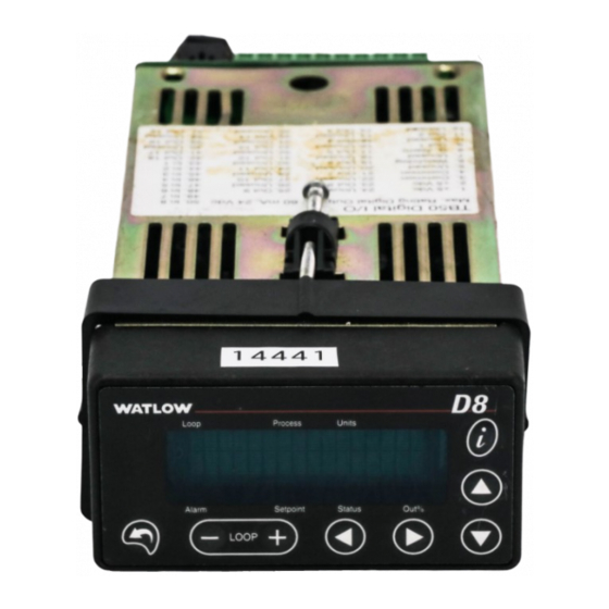
- Page 8 List of Figures Chapter 1: System Overview 13 Figure 1.1 – D8 Rear Views 17 Figure 1.2 – D8 Front Panel 18 Figure 1.3 – TB50 18 Chapter 2: Installation 20 Figure 2.1 – D8 System Components 21 Figure 2.2 – Clearance with DB25 and SCSI Cable 22 Figure 2.3 –...
- Page 9 D8 Series User’s Guide Chapter 4: Operation and Setup 61 Figure 4.1 – General Navigation Map 61 Figure 4.2 – Keypad Navigation 62 Figure 4.3 – Loop Display 62 Figure 4.4 – Loop Display with Alarm Code 63 Figure 4.5 – Display for Failed Sensor Alarm 64 Figure 4.6 –...
- Page 10 List of Tables Chapter 1: System Overview 13 Table 1.1 — Ordering Options 16 Chapter 2: Installation 20 Table 2.1 Cable Recommendations 26 – Table 2.2 Power Connections 29 – Table 2.3 — Analog Input Connections Mass Termination Option 32 Table 2.4 —...
- Page 11 D8 Series User’s Guide Table 3.24 – Control Instance Attributes (Instances 1 to 4 or 8) 55 Table 3.25 – Alarm Class and Services 56 Table 3.26 – Alarm Class Attributes (Instance 0) 56 Table 3.27 – Alarm Instance Attributes (Instances 1 to 4 or 8) 56 Table 3.28 –...
- Page 12 D8 Series User’s Guide Table 6.13 – Heat and Cool Output Types 116 Table 6.14 – Alarm Functions 122 Table 6.15 – Values for Alarm Hysteresis 126 Table 6.16 – Bit Positions for Alarm Enable and Alarm Function 133 Table 6.17 – Bit Positions for Alarm Status and Alarm Acknowledge 134 Table 6.18 –...
-
Page 13: Chapter 1: System Overview
System Overview Manual Contents This manual describes how to install, set up, and operate a D8 series controller. Each chapter covers a different aspect of your control system and may apply to different users: • Chapter 1: System Overview provides a component list and summary of features for the D8 series controllers. -
Page 14: Getting Started
Enter two points, and all input values are automatically scaled. Special inputs must be installed. • Dual Outputs: The D8 series includes both heat and cool control outputs for each loop. Independent control parameters are provided for each output. - Page 15 D8 Series User’s Guide Chapter 1: System Overview • Boost Output Function: Set digital outputs to function as boost on/off control in association with any alarm. • Flexible Alarms: Independently set high and low alarms and high and low deviation alarms for each loop.
-
Page 16: D8 Parts List
You may have received one or more of the following components. See Table 1.1 below for configuration information. • D8 series controller with mounting collar and brackets • TB50 with 50-pin SCSI cable • Special input resistors (installed in D8) Table 1.1 —... -
Page 17: Technical Description
Chapter 1: System Overview Technical Description This section contains a technical description of each component of the D8 series controller. The D8 is housed in a 1/8-DIN panel mount package. It contains the central processing unit (CPU), random access memory (RAM) with a built-in battery, flash memory, communications, digital I/O, analog inputs, display and touch keypad. -
Page 18: Tb50
Watlow provides optional cables to support installing the D8. A 50-pin SCSI cable connects the TB50 to the CLS200. Safety Watlow has made every effort to ensure the reliability and safety of this product. In addition, we have provided recommendations that will allow you to safely install and maintain this controller. External Safety Devices The D8 controller may fail full-on (100 percent output power) or full-off (0 percent output power), or may remain full-on if an undetected sensor failure occurs.v h... -
Page 19: Power-Fail Protection
Design your system to be safe even if the controller sends a 0 percent or 100 percent output power signal at any time. Install independent, external safety devices such as the Watlow TLM-8 that will shut down the system if a failure occurs. -
Page 20: Chapter 2: Installation
Chapter 2: Installation This chapter describes how to install the D8 series controller and its peripherals. Installation of the controller involves the following procedures: • Determining the best location for the controller • Mounting the controller and TB50 • Power connection •... -
Page 21: Mounting Controller Components
D8 Series User’s Guide Chapter 2: Installation D8 with SCSI Digital I/O D8 with Mass Termination TB50 Accessory Board Sensor Inputs DB25 Sensor Inputs SCSI Cable SCSI Connector SCSI Connector TB50 allows connection to... 19 Outputs for Control & Alarms... -
Page 22: Mounting The Controller
D8 Series User’s Guide Chapter 2: Installation Mounting the Controller Mount the controller before you mount the terminal block, or do any wiring. The controller’s placement affects placement and wiring considerations for the other components of your system. Ensure that there is enough clearance for mounting brackets, terminal blocks, and cable and wire connections. -
Page 23: Figure 2.5 - Mounting Bracket Clearance
D8 Series User’s Guide Chapter 2: Installation 4.02 in. (102 mm) Figure 2.5 – Mounting Bracket Clearance 1.80 ± 0.020 in. (45.7 ± 0.5 mm) 3.63 ± 0.020 in. (92.2 ± 0.5 mm) Figure 2.6 – Panel Thickness and Cutout Size We recommend you mount the controller in a panel not more than 0.2 in. -
Page 24: Mounting The Tb50
D8 Series User’s Guide Chapter 2: Installation Mounting the TB50 There are two ways you can mount the TB50: use the preinstalled DIN rail mounting brackets or use the plastic standoffs. Follow the corresponding procedure to mount the board. DIN Rail Mount Standoffs Figure 2.7 —... -
Page 25: Mounting The Power Supply
D8 Series User’s Guide Chapter 2: Installation Mounting with Standoffs 1. Remove the DIN rail mounting brackets from the TB50. 2. Select a location with enough clearance to remove the TB50, its SCSI cable and the controller itself. 3. Mark the four mounting holes. -
Page 26: Wiring Recommendations
D8 Series User’s Guide Chapter 2: Installation CAUTION! Do not wire bundles of low-voltage signal and control circuits next to bundles of high voltage ac wiring. High voltage may be inductively coupled onto the low- voltage circuits, which may damage the controller or induce noise and cause poor control. -
Page 27: Ground Loops
D8 series equipment. • If you must use electromechanical relays and you must place them in a panel with D8 series equipment, use a 0.01 microfarad capacitor rated at 1000VAC (or higher) in series with a 47Ω, 0.5 watt resistor across the normally open contacts of the relay load. -
Page 28: Power Connections
D8 Series User’s Guide Chapter 2: Installation The best way to avoid ground loops is to minimize unnecessary connections to ground. Do not connect any of the following terminals to each other or to earth ground: • Power supply dc common •... -
Page 29: Table 2.2 - Power Connections
D8 Series User’s Guide Chapter 2: Installation Table 2.2 Power Connections – FUNCTION POWER SUPPLY D8 J2 D8 TB2 DC Power (Controller) +12 to 24VDC J2-1 DC Common 12 to 24VDC Common J2-2 – Earth Ground Ground J2-3 1. Connect the dc common terminal on the power supply to the dc common (-) terminal on D8 TB2 or pin 2 on J2. -
Page 30: Connecting Tb50 To The D8
D8 Series User’s Guide Chapter 2: Installation solid-state relay (ssr) add jumper 5V COM +15V common 15V COM ground 1 2 3 4 -15V Serial Controller Ground digital-to-analog green converter AC Line black 120/240VAC AC Neutral white Figure 2.13 – Power Connections with the D8 Power Supply Connecting TB50 to the D8 1. -
Page 31: Digital Input Test
The controller can accept any mix of available input types. Some input types require that special scaling resistors be installed (done by Watlow before the controller is delivered). Sensors connect via a DB25 cable to J1 on units with the mass termination option for analog inputs and at screw terminals TB1 on units with at the screw termination option. -
Page 32: Table 2.3 - Analog Input Connections Mass Termination Option
D8 Series User’s Guide Chapter 2: Installation Table 2.3 — Analog Input Connections Mass Termination Option J1 (DB25) PIN NUMBER NAME IN FIGURES FUNCTION +CH1 Channel 1 positive input -CH1 Channel 1 negative input Analog common +CH2 Channel 2 positive input... -
Page 33: Input Wiring Recommendations
Terminals 11 to 18 are not used with a 4-loop controller. Input Wiring Recommendations Use multicolored stranded shielded cable for analog inputs. Watlow recommends that you use 20 AWG wire (0.5 mm ). If the sensor manufacturer requires it, you can also use 24 or 22 AWG wiring (0.2 mm... -
Page 34: Rtd Input Connections
Voltage Input Connections Voltage inputs with ranges greater than -10 to 60mV require accessory resistors. Special input resistors installed at Watlow divide analog input voltages such that the controller sees a -10 to 60mV signal on the loop. CH IN+... -
Page 35: Current Input Connections
Figure 2.17 – Current Signal Connections Wiring Control and Digital I/O This section describes how to wire and configure the control outputs for the D8 series controller. The D8 provides dual control outputs for each loop. These outputs can be enabled or disabled, and are connected through a TB50 or TB18. -
Page 36: Figure 2.18 - Digital Output Wiring
D8 Series User’s Guide Chapter 2: Installation All digital outputs sink current to controller common when on. The load may powered by the 5VDC supplied by the controller at the TB50, or by an external power supply. When using an external power supply, bear in mind: •... -
Page 37: Figure 2.19 - Sample Heat, Cool And Alarm Output Connections
D8 Series User’s Guide Chapter 2: Installation Control and Alarm Output Connections Typically control and alarm outputs use external optically-isolated solid state relays (SSRs). SSRs accept a 3 to 32VDC input for control, and some can switch up to 100 Amps at 480VAC. For larger currents, use silicon control rectifier (SCR) power controllers up to 1000 Amps at 120 to 600VAC. -
Page 38: Digital Inputs
D8 Series User’s Guide Chapter 2: Installation TB50 + 5VDC (Terminal 1) Watchdog Timer (Terminal 6) Figure 2.21 – TB50 Watchdog Timer Output TB18 + 5VDC (Terminal 1) Watchdog Timer (Terminal 3) Figure 2.22 – TB18 Watchdog Timer Output Digital Inputs All digital inputs are transistor-transistor logic (TTL) level inputs referenced to controller common and the internal +5V power supply of the D8. -
Page 39: Tb18 Connections
D8 Series User’s Guide Chapter 2: Installation External TB50 Switching Input Device Control Com Figure 2.23 – Wiring Digital Inputs Functions Activated by Digital Inputs Use digital inputs to activate the following functions: • Load a job that is stored in controller memory. See BCD Job Load on page 100. -
Page 40: Tb50 Connections
If you install a Watlow Serial DAC, the D8 series controller uses digital output 18 (terminal 15) for a clock line. You cannot use output 18 for anything else if a Serial DAC is installed. -
Page 41: Analog Outputs
A Dual DAC module includes two identical circuits. Each can convert a distributed zero cross (DZC) signal from the controller to a voltage or current signal. Watlow strongly recommends using a power supply separate from the controller supply to power the Dual DAC. Using a separate power supply isolates the controller’s digital logic circuits and analog measurement circuits from the frequently... -
Page 42: Connector Pinout
D8 Series User’s Guide Chapter 2: Installation Connector Pinout Figure 2.25 – J4 DeviceNet™ Connector Pinout Table 2.9 DeviceNet™ Connector – SIGNAL FUNCTION Shield Shield interconnect DeviceNet™ power DeviceNet™ power return CAN+ Positive side of the DeviceNet™ bus CAN- Negative side of the DeviceNet™ bus Network Length The network speed is limited by the end-to-end network distance. -
Page 43: Node Address (Mac Id)
D8 Series User’s Guide Chapter 2: Installation baud rate switch was changed to 250k baud before the network power had been restored, the controller will attempt to come back on the network at 250k baud. NOTE! When changing the baud rate via the software or by manually changing the switch position, you will need to cycle power on the network for the change to take effect. -
Page 44: Table 2.11 - Module Status Indicator Light
D8 Series User’s Guide Chapter 2: Installation Table 2.11 Module Status Indicator Light – INDICATOR LIGHT DESCRIPTION No power is applied to the device. Flashing Green-Red The device is performing a Self-Test. Green The device is operating normally. The device has detected an unrecoverable fault. -
Page 45: Chapter 3: Communicating By Devicenet
The EDS file allows for faster and easier configuration with the network software, but it is not required to make the device work. EDS files for the D8 are available on the Watlow web site and upon request from Watlow technical support. -
Page 46: Bit-Wise Values
D8 Series User’s Guide Chapter 3: Communicating by DeviceNet Bit-Wise Values Some settings, such as those that enable alarms, are stored as bits within words. To examine the value of just one bit, you can “and” the value with a mask word to extract the particular bit in which you are interested. -
Page 47: Master/Slave Connections
D8 Series User’s Guide Chapter 3: Communicating by DeviceNet Master/Slave Connections The D8 supports the Predefined Master/Slave Connection Set, which calls for the utilization of an Explicit Messaging Connection to manually create and configure Connection Objects within each connection end-point. These Connections are referred to collectively as the Predefined Master/Slave Connection Set. -
Page 48: Devicenet Objects
5 (5 hex) Status WORD Summary status of device 6 (6 hex) Serial Number UDINT Serial number of device Human readable ID “WATLOW D88” ( SHORT_ 7 (7 hex) Product Name 8-loop model or “WATLOW D84” STRING 4-loop model) Message Router Object The Message Router object provides a messaging connection point through which a client may address a service to any object class or instance residing in the physical device. -
Page 49: Devicenet Object
D8 Series User’s Guide Chapter 3: Communicating by DeviceNet Table 3.7 Message Router Instance Attributes – ATTRIBUTE ACCESS NAME TYPE DESCRIPTION Maximum number of connections Number 2 (2 hex) UINT supported. The D8 supports up to 3 Available connections. Number... -
Page 50: Table 3.11 - Assembly Class And Services
D8 Series User’s Guide Chapter 3: Communicating by DeviceNet Table 3.11 – Assembly Class and Services Class Code 04 hex Class Services None 0E hex Get Attribute Single Instance Services 10 hex Set Attribute Single Table 3.12 Assembly Instance Attributes –... -
Page 51: Figure 3.1 - Four-Loop Produced Static Input
D8 Series User’s Guide Chapter 3: Communicating by DeviceNet Byte Byte Byte Byte Byte Byte Byte Byte Exception Status 1 byte Loop 1 Process Variable Loop 2 Process Variable Loop 3 Process Variable Loop 4 Process Variable INT (2 bytes) -
Page 52: Connection Object
D8 Series User’s Guide Chapter 3: Communicating by DeviceNet Byte Byte Byte Byte Byte Byte Byte Byte Loop 1 Set Point Loop 2 Set Point Loop 3 Set Point Loop 4 Set Point INT (2 bytes) INT (2 bytes) INT (2 bytes) -
Page 53: Input Object
D8 Series User’s Guide Chapter 3: Communicating by DeviceNet ATTRIBUTE ACCESS NAME TYPE DESCRIPTION Specifies the Application Object(s) Produced 14 (E hex) EPATH whose data is to be produced by this Connection Path Connection Object. Consumed Number of bytes in the Consumed... -
Page 54: Output Object
D8 Series User’s Guide Chapter 3: Communicating by DeviceNet NOTE! All successful explicit message responses from a Set service will contain no data. The response will be a two-byte message containing the requester’s node address and service code (with R/R bit set). -
Page 55: Control Object
D8 Series User’s Guide Chapter 3: Communicating by DeviceNet ATTRIBUTE ACCESS NAME TYPE DESCRIPTION 118 (76 hex) Get/Set Heat SDAC Signal BOOL See page 117. 119 (77 hex) Get/Set Cool SDAC Signal BOOL See page 117. 120 (78 hex) Get/Set... -
Page 56: Alarm Object
D8 Series User’s Guide Chapter 3: Communicating by DeviceNet ATTRIBUTE ACCESS NAME TYPE DESCRIPTION 108 (6C hex) Get/Set Heat Filter USINT See page 114. 109 (6D hex) Get/Set Cool Filter USINT See page 114. 110 (6E hex) Get/Set Hysteresis UINT See page 115. -
Page 57: Pv Retransmit Object
D8 Series User’s Guide Chapter 3: Communicating by DeviceNet ATTRIBUTE ACCESS NAME TYPE DESCRIPTION 111 (6F hex) Get/Set Alarm Enable UINT See page 133. 112 (70 hex) Get/Set Alarm Function UINT See page 134. 113 (71 hex) Get/Set Alarm Acknowledge UINT See page 133. -
Page 58: Ratio Object
D8 Series User’s Guide Chapter 3: Communicating by DeviceNet Ratio Object The Ratio Object provides read/write access to all ratio parameters. Instance 0 of this object contains the class attributes listed in Table 3.32. The four-loop controller has four additional instances, and the eight-loop controller has eight additional instances, each containing the attributes listed in Table 3.33. -
Page 59: Global Object
D8 Series User’s Guide Chapter 3: Communicating by DeviceNet Table 3.35 – Cascade Class Attributes (Instance 0) ATTRIBUTE ACCESS NAME TYPE DESCRIPTION 1 (1 hex) Revision UINT Revision of this object 2 (2 hex) Max instance UINT Maximum instances of this object (8) - Page 60 D8 Series User’s Guide Chapter 3: Communicating by DeviceNet ATTRIBUTE ACCESS NAME TYPE DESCRIPTION 106 (6A hex) Get/Set Power Up Alarm Delay USINT See page 103. 107 (6B hex) Get/Set Power Up Loop Mode BOOL See page 103. 108 (6C hex)
-
Page 61: Chapter 4: Operation And Setup
Chapter 4: Operation and Setup This chapter explains how to use the keypad and display to operate the controller. This chapter also explains the basic concepts that you need to understand to set up and operate the controller. General Navigation Map The normal display on the D8 is the loop display. -
Page 62: Keypad
D8 Series User’s Guide Chapter 4: Operation and Setup Keypad l01 Set point 1000˚C Description Access the setup menus (press and hold for 3 seconds). Cancel a change without saving. Escape from a parameter to a top-level setup menu. Escape from a setup menu to the loop display or job display. -
Page 63: Alarm Displays
D8 Series User’s Guide Chapter 4: Operation and Setup The control modes are described in Table 4.1 Table 4.1 – Control Modes CONTROL MODE DESCRIPTION The loop is set to off. One or both outputs are enabled but both outputs are at 0%. -
Page 64: Figure 4.5 - Display For Failed Sensor Alarm
D8 Series User’s Guide Chapter 4: Operation and Setup For more information about alarms, see Setting Up Alarms on page 73 and Process Alarms on page 75. Failed Sensor Alarm Messages If the alarm is for a failed sensor, an alarm message appears in the first line of the loop display, as shown in Figure 4.5. -
Page 65: Job Display
D8 Series User’s Guide Chapter 4: Operation and Setup The keypad and display will not work for anything else until you acknowledge each alarm. The alarm code or message persists as long as the alarm condition exists. System Alarm Messages If a system alarm occurs, the alarm message replaces the entire display. -
Page 66: Changing The Set Point
D8 Series User’s Guide Chapter 4: Operation and Setup Changing the Set Point How to Manually Change the Set Point Start at the loop display and follow these steps: 1. Press to choose the appropriate loop. 2. Press . The Set point parameter should appear. If nothing happens, the keypad may be locked;... -
Page 67: Accessing And Navigating The Setup Menus
D8 Series User’s Guide Chapter 4: Operation and Setup To change the control mode and output power level, start at the loop display and do the following: 1. Press to choose the appropriate loop. 2. Press twice. The Mode parameter should appear. (If nothing happens, the keypad may be locked;... -
Page 68: Setting Up Closed-Loop Control
D8 Series User’s Guide Chapter 4: Operation and Setup 5. To edit a parameter: – Press to choose a value. < > – Press to save the new value and go to the next parameter. – Press to cancel a change without saving. -
Page 69: How To Set Up Closed-Loop Control
D8 Series User’s Guide Chapter 4: Operation and Setup How to Set Up Closed-Loop Control To set up closed-loop control: • Use the Input menu to specify the type of input signal and, if necessary, how to scale that signal. -
Page 70: Input Scaling Example: 4 To 20Ma Sensor
D8 Series User’s Guide Chapter 4: Operation and Setup Input Signal Figure 4.6 – Input Scaling The range for set points and alarms is bound by the process variables that correspond to the 0 percent and 100 percent input signals. Bear in mind that the range for set points and alarms is not bound by the low and high process variable ranges that you enter in the scaling parameters. -
Page 71: Input Scaling Example: 0 To 5Vdc
D8 Series User’s Guide Chapter 4: Operation and Setup Table 4.4 – Input Readings PROCESS VARIABLE READING IN PERCENT SENSOR INPUT DISPLAYED OF FULL SCALE 50.0 PSI 20mA 100% .0 PSI 100% x (4mA/20mA) = 20% Table 4.5 – Scaling Values... -
Page 72: Autotuning
D8 Series User’s Guide Chapter 4: Operation and Setup Table 4.7 – Scaling Values PARAMETER VALUE Input range high 65 GPM Input high signal 95.0% Input range low 3 GPM Input low signal 10.0% Autotuning Autotuning is a process by which a controller calculates the correct PID parameters for optimum control. -
Page 73: How To Autotune A Loop
D8 Series User’s Guide Chapter 4: Operation and Setup How to Autotune a Loop NOTE! The loop must be stable at a temperature well below the set point in order to successfully autotune. The controller will not complete tuning if the temperature exceeds 80 percent of set point before the new parameters are found. - Page 74 D8 Series User’s Guide Chapter 4: Operation and Setup What Happens if a Failed Sensor Alarm Occurs? If a failed sensor alarm occurs: • The controller switches to manual mode at the output power indicated by the Sensor fail heat output and Sensor fail cool output parameters in the Output menu.
-
Page 75: Process Alarms
D8 Series User’s Guide Chapter 4: Operation and Setup The RTD alarms are enabled on any loop with Input Type set to RTD. Restore Automatic Control After a Sensor Failure This feature returns a loop to automatic control after a failed sensor is repaired. To enable this feature: •... -
Page 76: Global Alarm
D8 Series User’s Guide Chapter 4: Operation and Setup Alarm High and Alarm Low An alarm high occurs if the process variable rises above a user-specified value. An alarm low occurs if the process variable drops below a separate user-specified value. See Figure 4.7 below. -
Page 77: Setting Up Process Variable Retransmit
D8 Series User’s Guide Chapter 4: Operation and Setup • A process alarm occurs and is unacknowledged. The global alarm occurs only if the alarm function is set to standard in the Alarms menu. (The global alarm does not occur if the alarm function is set to boost.) -
Page 78: Figure 4.8 - Application Using Process Variable Retransmit
D8 Series User’s Guide Chapter 4: Operation and Setup Loop 1 Input Process Variable Loop 1 PID Output Loop 2 PID Output Furnace Heater Serial Power Controller To Data Logger Figure 4.8 – Application Using Process Variable Retransmit Table 4.8 shows the parameter setup for this example. -
Page 79: Setting Up Cascade Control
D8 Series User’s Guide Chapter 4: Operation and Setup Setting Up Cascade Control Cascade control is used to control thermal systems with long lag times, which cannot be as accurately controlled with a single control loop. The output of the first (primary) loop is used to adjust the set point of the second (secondary) loop. -
Page 80: Proportional-Only Control On The Primary Loop
D8 Series User’s Guide Chapter 4: Operation and Setup High Set Point Low Set Point 100% Output of Primary Loop (Percent of Full Scale) Figure 4.10 – Secondary Set Point When Primary Loop Has Heat Output Only Proportional-Only Control on the Primary Loop The PID parameters of the primary loop must be tuned to produce the desired effect on the set point of the secondary loop. -
Page 81: Figure 4.11 - Example Application Using Cascade Control
D8 Series User’s Guide Chapter 4: Operation and Setup Using cascade control, the outer thermocouple is used on the primary loop (in this example, loop 1), and the inner thermocouple is used on the secondary loop (loop 2). The heater is controlled by loop 2. -
Page 82: Setting Up Ratio Control
D8 Series User’s Guide Chapter 4: Operation and Setup As the temperature in the middle of the tank (loop 1) drops, the output goes up proportionally and the set point of loop 2 goes up proportionally. Thus heat is added to the system at the element even though the temperature near the element may have been at the desired temperature. -
Page 83: How To Set Up Ratio Control
D8 Series User’s Guide Chapter 4: Operation and Setup High SP Low SP SP Differential Input Range Input Range High Master Loop Process Variable SP = Set Point PV = Process Variable Figure 4.13 – Relationship Between the Process Variable on the Master Loop and the Set Point of the Ratio Loop NOTE! Ratio control cannot be used on the same control loop as cascade control. -
Page 84: Setting Up Differential Control
D8 Series User’s Guide Chapter 4: Operation and Setup Loop 1: Water Flow Control Loop KOH Input Water Input Loop 2: KOH Flow Control Loop Loop 1 Input Loop 1 PID Output Process Variable Flow Transducer Loop 2 Input Process Variable... -
Page 85: Differential Control Example: Thermoforming
D8 Series User’s Guide Chapter 4: Operation and Setup Differential Control Example: Thermoforming A thermal forming application requires that the outer heaters run 50ºF hotter than the center heaters. The center heaters use infrared (IR) sensors for temperature feedback. The outer heaters use thermocouples for feedback. -
Page 86: Remote Analog Set Point Example: Changing A Set Point With A Plc
D8 Series User’s Guide Chapter 4: Operation and Setup Remote Analog Set Point Example: Changing a Set Point with a PLC A PLC provides a 0 to 5VDC signal representing 0 to 300°F as a remote set point input to the D8. -
Page 87: Chapter 5: Tuning And Control
Chapter 5: Tuning and Control This chapter describes the different methods of control available with the D8. This chapter covers control algorithms, control methods, PID control, starting PID values and tuning instructions to help appropriately set control parameters in the D8 system. Control Algorithms This section explains the algorithms available for controlling a loop. -
Page 88: Proportional Control (P)
D8 Series User’s Guide Chapter 5: Tuning and Control Heat Off Heat Off Set Point Process Heat On ˚ 1000 Variable Set Point - Hysteresis Output ˚ Figure 5.1 – On/Off Control Proportional Control (P) Proportional control eliminates cycling by increasing or decreasing the output proportionally with the process variable’s deviation from the set point. -
Page 89: Proportional And Integral Control (Pi)
D8 Series User’s Guide Chapter 5: Tuning and Control Proportional and Integral Control (PI) With proportional and integral control, the integral term corrects for offset by repeating the proportional band’s error correction until there is no error. For example, if a process tends to settle about 5°F below the set point, appropriate integral control brings it to the desired setting by... -
Page 90: Heat And Cool Outputs
D8 Series User’s Guide Chapter 5: Tuning and Control Heat and Cool Outputs Each loop may have one or two outputs. Often a heater is controlled according to the feedback from a thermocouple, in which case only one output is needed. -
Page 91: Integral Settings
D8 Series User’s Guide Chapter 5: Tuning and Control Integral Settings The controller’s integral parameter is set in seconds per repeat. Some other products use an integral term called reset, in units of repeats per minute. Table 5.2 shows integral settings versus reset settings. -
Page 92: General Pid Constants By Application
D8 Series User’s Guide Chapter 5: Tuning and Control General PID Constants by Application This section gives PID values for many applications. They are useful as control values or as starting points for PID tuning. Proportional Band Only (P) • Set the proportional band to seven percent of the set point. -
Page 93: Control Outputs
D8 Series User’s Guide Chapter 5: Tuning and Control Control Outputs The controller provides open collector outputs for control. These outputs normally control the process using solid state relays. Open collector outputs can be configured to drive a serial digital-to-analog converter (Serial DAC) which, in turn, can provide 0 to 5VDC, 0 to 10VDC or 4 to 20mA control signals to operate field output devices. -
Page 94: Output Filter
D8 Series User’s Guide Chapter 5: Tuning and Control The combination of DZC output and a solid state relay can inexpensively approach the effect of analog, phase-angle fired control. Note, however, DZC switching does not limit the current and voltage applied to the heater as phase-angle firing does. -
Page 95: Chapter 6: Menu And Parameter Reference
Chapter 6: Menu and Parameter Reference The D8 has operator and setup parameters that let you change the configuration of the controller. This section contains the following information for each operator and setup parameter: • Description • Values • Default value •... -
Page 96: Mode
D8 Series User’s Guide Chapter 6: Menu and Parameter Reference Values: For thermocouples and RTD inputs, same as the input range (see Table 6.7). For process inputs, any value between the Input range low and Input range high parameters in the Input menu. -
Page 97: Process Variable
D8 Series User’s Guide Chapter 6: Menu and Parameter Reference Process Variable 925 ˚F 1000man Indicates the value measured by the sensor after filtering and scaling. This parameter is read-only. Values: For thermocouples and RTD inputs, same as the input range (Table 6.7 – Input Types and Ranges on page 107). -
Page 98: Figure 6.2 - Setup Menus And Parameters
D8 Series User’s Guide Chapter 6: Menu and Parameter Reference Global setup Navigation for the Setup Menus Load setup from job Access the setup menus (press and hold for 3 seconds) Save setup as job Cancel a change without saving. -
Page 99: Global Setup Menu
D8 Series User’s Guide Chapter 6: Menu and Parameter Reference Global Setup Menu Global setup Other menus Use the Global setup menu to set parameters that affect all loops. Load Setup From Job Load setup from job none Load one of the jobs stored in battery-backed RAM. The following parameters are loaded for each loop as part of a job: •... -
Page 100: Save Setup As Job
D8 Series User’s Guide Chapter 6: Menu and Parameter Reference Save Setup As Job Save setup as none Save the current settings as one of eight jobs in the batterybacked RAM. The following parameters are saved for each loop as part of a job: •... -
Page 101: Bcd Job Load Logic
D8 Series User’s Guide Chapter 6: Menu and Parameter Reference Table 6.3 – Values for BCD Job Load DISPLAY DeviceNet™ DESCRIPTION VALUE VALUE Use digital input 1 for remote selection of jobs 1 and 2. use D/I 1 Use digital inputs 1 and 2 for remote selection of jobs 1 to 4. -
Page 102: Mode Override
D8 Series User’s Guide Chapter 6: Menu and Parameter Reference Mode Override Mode override disabled Choose the digital input to use for the mode override feature. When the input is activated, the controller sets all loops to manual mode at the output levels specified at the Sensor fail heat output and Sensor fail cool output parameters in the Output menu. -
Page 103: Power Up Alarm Delay
D8 Series User’s Guide Chapter 6: Menu and Parameter Reference Power Up Alarm Delay Power up alarm delay 0 min Specify how long to delay high, low and deviation alarms on all loops during powerup. This feature does not delay failed sensor alarms. -
Page 104: Keypad Lock
D8 Series User’s Guide Chapter 6: Menu and Parameter Reference Keypad Lock Keypad lock Set this parameter to on to disable the key on the keypad. This restricts access to the operator parameters from the controller keypad. Values: on (1) or off (0). Values in parentheses are for communications, and are stored as the second bit of the system command word, so set or read only that bit. -
Page 105: Digital Output Alarm Polarity
D8 Series User’s Guide Chapter 6: Menu and Parameter Reference Digital Output Alarm Polarity D/O alarm polarity Choose the polarity of all digital outputs used for alarms. This setting does not apply to the global alarm output or the CPU watchdog output. -
Page 106: Module Led
D8 Series User’s Guide Chapter 6: Menu and Parameter Reference Module LED <Module LED green Indicates the status of the Module LED. Values: off, green, red, flashing red, flashing green. Table 2.11 – Module Status Indicator Light on page 44 DeviceNet™... -
Page 107: Input Menu
D8 Series User’s Guide Chapter 6: Menu and Parameter Reference Input Menu 01 Input Other menus Use the Input menu to configure the process input: • Input type • Engineering units • Scaling, calibration and filtering. Input Type 01 Input type J t/c Choose the type of sensor that is connected to the analog input. -
Page 108: Loop Name
D8 Series User’s Guide Chapter 6: Menu and Parameter Reference Loop Name 01 Loop name Enter a two-character name for the loop. This name is shown on the controller display in place of the loop number. Values: See Table 6.8. -
Page 109: Calibration Offset
D8 Series User’s Guide Chapter 6: Menu and Parameter Reference Calibration Offset 01 Calibration offset 0 ˚F For a thermocouple or RTD input, enter the offset to correct for signal inaccuracy. A positive value increases the reading and a negative value decreases it. Use an independent sensor or your own calibration equipment to find the offset for your system. -
Page 110: Display Format
D8 Series User’s Guide Chapter 6: Menu and Parameter Reference Display Format 01 Disp format -999to 3000 For a process input, choose the range and the number of decimal places for the process variable and related parameters. Choose a precision appropriate for the range and accuracy of the sensor. -
Page 111: Input High Signal
D8 Series User’s Guide Chapter 6: Menu and Parameter Reference Input High Signal 01 Input high signal 100.0% For a process input, enter the input signal level that corresponds to the value for the Input range high parameter. The high signal is a percentage of the full scale input range. -
Page 112: Input Filter
D8 Series User’s Guide Chapter 6: Menu and Parameter Reference Decimal Placement for DeviceNet™: Decimal Placement for Percentage Values on page 46 DeviceNet™ Object: Input (64 hex) Input Filter 01 Input filter 3scans Choose the amount of filtering to apply to the process variable before the value is displayed or used in the control calculation. -
Page 113: Heat/Cool Proportional Band
D8 Series User’s Guide Chapter 6: Menu and Parameter Reference Heat/Cool Proportional Band 01 Heat prop band 40 ˚F Enter the proportional band. A larger value yields less proportional action for a given deviation from set point. Values: For a thermocouple or RTD input, see Table 6.11. For a process input, 1 to the span of the input range (Input range high - Input range low). -
Page 114: Heat/Cool Derivative
D8 Series User’s Guide Chapter 6: Menu and Parameter Reference Heat/Cool Derivative 01 Heat de- rivative 0 sec Enter the derivative constant. A larger value yields greater derivative action. Values: 0 to 255 seconds Default: 0 DeviceNet™ Object: Control (66 hex) -
Page 115: 01 Hysteresis
D8 Series User’s Guide Chapter 6: Menu and Parameter Reference Hysteresis 01 Hysteresis 5 ˚C Specify how much the process variable must deviate from set point before the output can switch between on and off (for on/off control) or switch between heating and cooling (for heat/cool control). -
Page 116: Output Menu
D8 Series User’s Guide Chapter 6: Menu and Parameter Reference Output Menu 01 Output Other menus Use the Output menu to enable and configure heat and cool outputs. Heat/Cool Output Type 01 Heat output type Choose the output type, or disable the heat or cool output. For more information about each output type, Chapter 5: Tuning and Control on page 87 (If an output is used for process variable retransmit, the disabled option is not available. -
Page 117: Heat/Cool Cycle Time
D8 Series User’s Guide Chapter 6: Menu and Parameter Reference Heat/Cool Cycle Time 01 Heat cycle time 10sec For a time-proportioning output, enter the cycle time in seconds. For more information about cycle time, Time Proportioning (TP) on page 93... -
Page 118: Heat/Cool Sdac High Signal
D8 Series User’s Guide Chapter 6: Menu and Parameter Reference Heat/Cool SDAC High Signal 01 Ht SDAC hi signal 10.00vdc For a Serial DAC output, enter the high output signal level for the Serial DAC. The Serial DAC converts 100 percent output from the controller to the value set here. -
Page 119: Heat/Cool Power Limit Time
D8 Series User’s Guide Chapter 6: Menu and Parameter Reference Decimal Placement for DeviceNet™: Decimal Placement for Percentage Values on page 46 DeviceNet™ Object: Output (65 hex) Heat/Cool Power Limit Time 01 HtPwr limit time continuous Enter the duration of the power limit set at the previous parameter, or choose continuous to keep the limit in effect at all times. -
Page 120: Open Thermocouple Heat/Cool Output Average
D8 Series User’s Guide Chapter 6: Menu and Parameter Reference Open Thermocouple Heat/Cool Output Average 01 Open T/C ht out average If you set this parameter to on and a thermocouple open alarm occurs, a loop set to automatic control mode will switch to manual mode at the average output prior to the alarm. -
Page 121: Alarms Menu
D8 Series User’s Guide Chapter 6: Menu and Parameter Reference Alarms Menu 01 Alarms Other menus Use the Alarms menu to configure high alarms, low alarms, and deviation alarms, including: • Alarm set points • Alarm outputs • Alarm behavior •... -
Page 122: Alarm High Output
D8 Series User’s Guide Chapter 6: Menu and Parameter Reference Table 6.14 – Alarm Functions VALUE DESCRIPTION No alarm function. Alarm is indicated and logged. Latching global alarm is activated. standard Alarm must be acknowledged to clear. Optional non-latching alarm output is activated. -
Page 123: High Deviation Function
D8 Series User’s Guide Chapter 6: Menu and Parameter Reference High Deviation Function 01 HiDeviation func Choose whether the alarm functions as an alarm or as a boost output, or disable the alarm. Values: Table 6.14 – Alarm Functions on page 122 Default: off DeviceNet™... -
Page 124: Low Deviation Function
D8 Series User’s Guide Chapter 6: Menu and Parameter Reference Low Deviation Function 01 LoDeviation func Choose whether the alarm functions as an alarm or as a boost output, or disable the alarm. Values: Table 6.14 – Alarm Functions on page 122. -
Page 125: Alarm Low Function
D8 Series User’s Guide Chapter 6: Menu and Parameter Reference Alarm Low Function 01 Alarm low func Choose whether the alarm functions as an alarm or as a boost output, or disable the alarm. Values: See Table 6.14 . Default: off DeviceNet™... -
Page 126: 01 Alarm Delay
D8 Series User’s Guide Chapter 6: Menu and Parameter Reference Table 6.15 – Values for Alarm Hysteresis VALUES VIA INPUT TYPE DISPLAY FORMAT VALUES DEFAULT COMMUNICATIONS Thermocouple 0 to 500 0 to 5000 0 to 500.0 0 to 5000 -999 to 3000... -
Page 127: Heat/Cool Output Retransmit
D8 Series User’s Guide Chapter 6: Menu and Parameter Reference Heat/Cool Output Retransmit 01 Heat output retrans PV Choose the loop that provides the process variable to be retransmitted. For example, in the sample display above, the heat output from loop 1 (01) will retransmit the process variable from loop 2. -
Page 128: Cascade Menu
D8 Series User’s Guide Chapter 6: Menu and Parameter Reference Cascade Menu 01 Cascade Other menus Use the cascade menu to configure cascade control. Use cascade control to calculate the set point of the current loop (the secondary, or outer, loop) based upon the output of another loop (the primary, or inner, loop). -
Page 129: Cascade High Set Point
D8 Series User’s Guide Chapter 6: Menu and Parameter Reference Cascade High Set Point 01 Cascade hi 25 ˚C Enter the set point to use for the current loop when the output of primary loop is at its maximum value. The set point will never exceed this value. -
Page 130: Ratio Low Set Point
D8 Series User’s Guide Chapter 6: Menu and Parameter Reference Default: none (0) DeviceNet™ Object: Ratio (69 hex) Ratio Low Set Point 01 Ratio low 25 ˚C Enter the lowest allowable set point for the current loop. The set point will never drop below this value, regardless of the result of the ratio calculation. -
Page 131: Ratio Set Point Differential
D8 Series User’s Guide Chapter 6: Menu and Parameter Reference Values: .1 to 999.9 (1 to 9999). Values in parentheses are for communications (values are in tenths). Default: 1.0 (10) for a thermocouple, RTD or process input. DeviceNet™ Object: Ratio (69 hex) -
Page 132: Keypad Test
D8 Series User’s Guide Chapter 6: Menu and Parameter Reference Keypad Test Keypad test press to begin To test the keypad, press . This screen will appear: < Ends test key pressed= To test a key, press it. If the key is working properly, an icon for that key appears. -
Page 133: Parameters Only Available Via Communications
D8 Series User’s Guide Chapter 6: Menu and Parameter Reference NOTE! When you exit the I/O tests menu, all outputs that were forced on are turned off. Parameters Only Available via Communications These parameters are available only via communications. They are not accessible through the controller keypad. -
Page 134: Alarm Function
D8 Series User’s Guide Chapter 6: Menu and Parameter Reference Alarm Function Choose whether an alarm behaves as a standard alarm or as a boost output. For descriptions of the standard and boost functions. See Table 6.14 – Alarm Functions on page 122. Table 6.16 – Bit Positions for Alarm Enable and Alarm Function on page 133 shows the bit to read for each alarm. -
Page 135: Heat/Cool Output Action For Watchdog Inactivity Fault
D8 Series User’s Guide Chapter 6: Menu and Parameter Reference Table 6.18 – System Status Bits DeviceNet™ PARAMETER DESCRIPTION VALUES OBJECT Indicates whether the values in RAM 0: No corruption detected Battery Status have been corrupted while the power Global (6) 1: Data corrupted has been off. -
Page 136: Chapter 7: Troubleshooting And Reconfiguring
If the troubleshooting procedures in this chapter do not solve your system’s problems, call Application Engineering for additional troubleshooting help. If you need to return the unit to Watlow for testing and repair, Customer Service will issue you an RMA number. See Return Material Authorization (RMA) on page 3. -
Page 137: Process Alarms
D8 Series User’s Guide Chapter 7: Troubleshooting and Reconfiguring Process Alarms When a process alarm occurs, the controller switches to the single-loop display for the loop with the alarm and displays the alarm code (see Alarm Displays on page 63). -
Page 138: Ambient Warning
D8 Series User’s Guide Chapter 7: Troubleshooting and Reconfiguring Ambient Warning The Ambient Warning indicates that the controller is within 5°C of its operating temperature limits. If an Ambient Warning occurs, the alarm code AW (flashing) is displayed, and the global alarm output is turned on. -
Page 139: Reading The Devicenet Indicator Lights
D8 Series User’s Guide Chapter 7: Troubleshooting and Reconfiguring SYMPTOM POSSIBLE CAUSES RECOMMENDED ACTION Keypad locked See Keys Do Not Work on page 142. An alarm condition exists and has not been D8 display is lit, but Unacknowledged alarm acknowledged. See How to Acknowledge an Alarm on keys do not work page 64. -
Page 140: Corrective And Diagnostic Procedures
D8 Series User’s Guide Chapter 7: Troubleshooting and Reconfiguring Table 7.4 – Network Status Indicator Light INDICATOR LIGHT DESCRIPTION The device is not online. The device has not completed the duplicate MAC ID test yet. The device may not be powered. Look at Table 2.10, Module Status Indicator Light. -
Page 141: H/W Error: Gain Or Offset
D8 Series User’s Guide Chapter 7: Troubleshooting and Reconfiguring NOTE! The controller retains its settings when powered. The battery is required to keep the settings in memory only while the controller is not powered. To replace the battery: 1. Contact your supplier to obtain a replacement battery. -
Page 142: Keys Do Not Work
D8 Series User’s Guide Chapter 7: Troubleshooting and Reconfiguring a. Switch off power to the controller. b. Remove the board assembly from the D8 housing. See Replacing the EPROM on page 145, steps 2 to 5. c. Reseat the board assembly and reassemble the controller. Reverse the steps refered to above to reseat. -
Page 143: Earth Grounding
D8 Series User’s Guide Chapter 7: Troubleshooting and Reconfiguring 4. Verify the sensors: • For thermocouples, remove the thermocouple leads and use a digital voltmeter to measure the resistance between the positive and negative thermocouple leads. A value of 2 to 20Ω is normal. Readings in excess of 20Ω indicate a problem with the sensor. -
Page 144: Testing Control Output Devices
D8 Series User’s Guide Chapter 7: Troubleshooting and Reconfiguring Testing Control Output Devices Connect the solid-state relay (SSR) control terminals to the D8 control output and connect a light bulb (or other load that can easily be verified) to be switched by the SSR’s outputs. Put the loop in manual mode and set the output to 100 percent. -
Page 145: Clearing The Ram
D8 Series User’s Guide Chapter 7: Troubleshooting and Reconfiguring Clearing the RAM Clearing the random access memory (RAM) returns all controller settings to their defaults. All stored jobs are also cleared from controller memory. To clear the RAM: 1. Make a record of all controller settings. -
Page 146: Figure 7.2 - Disconnect Keypad Ribbon Cable From Processor Board
D8 Series User’s Guide Chapter 7: Troubleshooting and Reconfiguring 5. Unplug the front panel overlay ribbon cable from the connector on the processor board (the bottom one in the stack of two boards). Figure 7.2 — Disconnect Keypad Ribbon Cable from Processor Board 6. -
Page 147: Removing Or Replacing The Battery
D8 Series User’s Guide Chapter 7: Troubleshooting and Reconfiguring Figure 7.5 — EPROM Location 9. Remove the existing EPROM from its socket with an IC extraction tool or a jeweler’s flathead screwdriver. Figure 7.6 — Remove EPROM 10. Carefully insert the new EPROM into the socket. Make sure that the chip is oriented so that its notch fits in the corresponding corner of the socket. -
Page 148: Scaling Resistors
D8 Series User’s Guide Chapter 7: Troubleshooting and Reconfiguring Figure 7.7 — Battery-Backed RAM Module on the Processor Board To replace the battery, if desired: 1. Align the contact springs on the battery holder with the contacts on the RAM module. -
Page 149: Current Inputs
D8 Series User’s Guide Chapter 7: Troubleshooting and Reconfiguring RC (Voltage) Internal +5VDC To D8 Reference Analog Circuitry Input Terminal RC (RTD) Figure 7.8 – Input Circuit Current Inputs Each current input has a 3.0Ω resistor in the resistor pack (RP) location for the input. Note the resistor pack locations have three through-holes. -
Page 150: Rtd Inputs
D8 Series User’s Guide Chapter 7: Troubleshooting and Reconfiguring RESISTOR VALUES INPUT RANGE 0 to 5VDC 39.2kΩ 475.0Ω 0 to 10VDC 49.9kΩ 301.0Ω Resistor tolerance: ±0.1% Table 7.8 – Resistor Locations for Voltage Inputs RESISTOR LOCATIONS LOOP RTD Inputs Each RTD input has three scaling resistors installed: one each at RA, RB and RC for the input. RA and RB are a matched pair of resistors installed in the resistor pack (RP) location as shown in the illustration below. -
Page 151: Scaling And Calibration
D8 Series User’s Guide Chapter 7: Troubleshooting and Reconfiguring RESISTOR LOCATIONS LOOP RA/RB Scaling and Calibration The controller provides offset calibration for thermocouple, RTD, and other fixed ranges, and offset and span (gain) calibration for process inputs. In order to scale the input signal, you must: 1. - Page 152 D8 Series User’s Guide Chapter 7: Troubleshooting and Reconfiguring...
-
Page 153: Chapter 8: Specifications
Chapter 8: Specifications This chapter contains specifications for the D8 series controllers, TB50 terminal board, Dual DAC module, Serial DAC module and the D8 power supply. System Specifications This section contains D8 series controller specifications for environmental specifications and physical dimensions, inputs, outputs, the serial interface and system power requirements. -
Page 154: Figure 8.1 - D8 Module Dimensions Without Cables
D8 Series User’s Guide Chapter 8: Specifications 3.80 in. (96 mm) 1.98 in. (50 mm) 1.76 in. (45 mm) 6.12 in. (155 mm) 8.40 in. (213 mm) 7.40 in. (188 mm) 3.55 in. (90 mm) Figure 8.1 – D8 Module Dimensions Without Cables Table 8.3 –... -
Page 155: Figure 8.3 - Clearance With Terminal Blocks (Tb1 & Tb18)
D8 Series User’s Guide Chapter 8: Specifications 2.44 in. (62 mm) 1.98 in. (50 mm) 1.00 in. (25 mm) 8.40 in. (213 mm) Figure 8.3 – Clearance with Terminal Blocks (TB1 & TB18) 2.44 in. (62 mm) 1.98 in. (50 mm) 1.00 in. -
Page 156: Figure 8.5 - Tb50 Dimensions
D8 Series User’s Guide Chapter 8: Specifications Table 8.5 – TB50 Physical Dimensions Weight 0.32 lb. 0.15kg Length 4.1 inches 104 mm Width 4.0 inches 102 mm Height 1.5 inches 37 mm Height Off Panel 0.92 inches 23 mm (DIN Brackets Removed) 4.1 in. -
Page 157: Inputs
D8 Series User’s Guide Chapter 8: Specifications 6.4 in. (163 mm) 1.5 in. (37 mm) 4.0 in. (102 mm) Figure 8.6 – TB50 Dimensions with SCSI Cable Inputs The controller accepts analog sensor inputs which are measured and may be used as feedback for control loops. -
Page 158: Table 8.9 - Thermocouple Range And Resolution
D8 Series User’s Guide Chapter 8: Specifications Calibration Automatic zero and full scale Analog Ground to Frame Ground Maximum DC Common to Frame Ground Maximum Potential Open Thermocouple Detection Pulse type for upscale break detection Table 8.9 – Thermocouple Range and Resolution... -
Page 159: Outputs
An open-collector CPU watchdog output is also provided so that an external device can monitor the CPU state. Analog Outputs Contact your supplier or Watlow for more information on these accessory products. Contact your supplier or Watlow for more information on these accessory products. Digital Outputs Table 8.13 –... -
Page 160: Table 8.14 - 5Vdc Output (Power To Operate Solid-State Relays)
D8 Series User’s Guide Chapter 8: Specifications Table 8.14 – 5VDC Output (Power to Operate Solid-State Relays) Voltage 5VDC Maximum Current 350mA Table 8.15 – Communications Minimum Time Between 20ms Polled I/O Requests Table 8.16 – D8 Power Requirements Voltage... -
Page 161: Glossary
Glossary Ambient Temperature The temperature of the air or other medium that surrounds the components of a thermal system. See Alternating Current. American Wire Gauge (AWG) AC Line Frequency A standard of the dimensional characteristics The frequency of the ac line power measured in of wire used to conduct electrical current or Hertz (Hz), usually 50 or 60Hz. - Page 162 D8 Series User’s Guide Closed Loop See American Wire Gauge. A control system that uses a sensor to measure a process variable and makes decisions based on that feedback. Cold Junction Baud Rate Connection point between thermocouple metals The rate of information transfer in serial and the electronic instrument.
- Page 163 D8 Series User’s Guide Default Parameters Distributed Zero Crossing (DZC) The programmed instructions that are A form of digital output control in which the permanently stored in the microprocessor output on/off state is calculated for every ac software. line cycle. Power is switched at the zero cross, which reduces electrical noise.
- Page 164 High Power Digital Filter — A filter that slows the (As defined by Watlow) Any voltage above response of a system when inputs change 24VAC or VDC and any current level above unrealistically or too fast. Equivalent to a 50mA AC or mA DC.
- Page 165 D8 Series User’s Guide Process Hysteresis — In heat/cool applications, the +/- difference between heat Keypad Lock and cool. Also known as process deadband A feature that prevents operation of the keypad by unauthorized people. Input Analog Input — An input that accepts process variable information.
- Page 166 D8 Series User’s Guide DAC or analog. Also the description of the electrical hardware that makes up the output. Noise Unwanted electrical signals that usually produce Overshoot signal interference in sensors and sensor The amount by which a process variable circuits.
- Page 167 D8 Series User’s Guide Ramp Serial Communications A programmed change in the temperature of a A method of transmitting information between set point system. devices by sending all bits serially over a single communication channel. Range The area between two limits in which a quantity Set Point (SP) or value is measured.
- Page 168 D8 Series User’s Guide Thermocouple Extension Wire A grade of wire used between the measuring Volt (V) junction and the reference junction of The unit of measure for electrical potential, a thermocouple. Extension wire and voltage or electromotive force (EMF). See also thermocouple wire have similar properties, but Voltage.
-
Page 169: Index
Index Application Objects 46 Assembly Object 49 AC Line Frequency 60, 104 attribute 45, 47 Address, see also Node Address 47 automatic mode agency compliance 153 Mode parameter 96 AH alarm code 64 restoring after failed sensor repair 75 AL alarm code 64 setting 66 Alarm Acknowledge 57, 133 auto message on loop display 63... - Page 170 D8 Series User’s Guide characteristics 16 Cool Filter 56, 114 checksum 30, 106 Cool Integral 55, 113 class 47 Cool Manual Reset 55, 114 Clearing the RAM 145 cool message on loop display 63 closed-loop control 68 Cool Output Action for Watchdog 55...
- Page 171 D8 Series User’s Guide remote job selection 100 Fahrenheit 108 restoring automatic control after sensor failed sensor alarms failure 115 behavior of 138 specifications 159 codes 63, 64 technical information 38 messages 63, 64 testing 31, 131 output power if sensor alarm occurs 119...
- Page 172 D8 Series User’s Guide Heat Retransmit High Process Variable 57, location 21 overview 20 Heat Retransmit Low Process Variable 57, panel hole dimensions 23 power supply 25, 28 Heat SDAC High Signal 55, 118 sensor input wiring 31 Heat SDAC Low Signal 55, 117...
- Page 173 D8 Series User’s Guide loops status indicator 106 closed-loop control 68 Network Length 42 display information 62 Network Status Indicator 41, 44, 106, 140 naming 108 Node Address 49, 105 number available 157 switch 43, 49, 105 tuning 90 noise...
- Page 174 D8 Series User’s Guide ratio control 129 PV Retransmit Object 57 restoring all default settings 145 Serial DAC 117 parts list 16 clearing 145 settings for various applications 92 erasure of during flash memory settings from other controllers 91 replacement 145...
- Page 175 D8 Series User’s Guide SCSI cable 17, 18 TB18 clearance 22, 154 alarm outputs 37 installing 30 connections 39 Sensor Fail Cool Output 54, 119 CPU watchdog timer output 37 and failed sensor alarm 73 digital output wiring 36 mode override 102...
- Page 176 D8 Series User’s Guide TO alarm code 64 TR alarm code 64 troubleshooting 136 alarms 137 all loops are set to manual 0% 139 Battery Dead alarm 140 check these things first 136 control mode switches unexpectedly 139 control outputs 144...
-
Page 177: Menu Structure
D8 Series User’s Guide Menu Structure GLOBAL SETUP OUTPUT PV RETRANS Load Setup from job Heat output Heat output retrans PV Save setup as job Heat cycle time Ht retrans LowPV BCD job load Heat SDAC signal Ht retrans HighPV... -
Page 178: Declaration Of Conformity
D8 Series User’s Guide Declaration of Conformity... -
Page 179: How To Reach Us
电子邮件: info-cn@watlow.com Website: www.watlow.co.jp 网站: www.watlow.com Watlow Korea Co., Ltd. Watlow Electric Manufacturing Company (Shanghai) Co. Ltd. #2208, Hyundia KIC Building B, 70 Doosan-ro Greenland International Plaza Room 1306 Geumcheon-gu, Seoul 275-8 East Guoding Road, Yangpu District Republic of Korea...
Need help?
Do you have a question about the D8 Series and is the answer not in the manual?
Questions and answers