Table of Contents
Advertisement
Quick Links
Advertisement
Table of Contents
Troubleshooting

Related Manuals for Watlow CLS200


Summary of Contents for Watlow CLS200
- Page 1 CLS200 User’s Guide...
- Page 2 AVERTISSEMENT! Risques de choc électrique. Coupez le WARNING! To reduce the risk of fire or electric shock, install courant de votre processus tout entier avant de commencer à the CLS200 in a controlled environment, relatively free of installer le régulateur. contaminants.
- Page 3 Material Authorization (RMA) number before returning any failed product to Watlow. If you do not know why the product This product is warranted by Watlow for a period of 36 months in failed, contact an Application Engineer. All RMA’s require: accordance with the terms and conditions set forth on Watlow’s...
-
Page 4: Table Of Contents
Using Alarms 59 Power Connections 29 Alarm Delay 59 Wiring the Power Supply 29 Failed Sensor Alarms 59 Connecting TB50 to CLS200 31 Process Alarms 61 Testing Your System 31 Global Alarm 63 TB50 or TB18 Test 31 Ramp/Soak 63... - Page 5 CLS200 Series User’s Guide Power Up Output Status 71 Digital Output Number 94 Process Power Digital Input 71 Keypad Test 95 Controller Address 72 Display Test 95 Communications Baud Rate 72 Chapter 5: Enhanced Features—96 Communications Protocol 72 Communications Error Checking 72...
- Page 6 PI with Derivative (PID) 138 Chapter 10: Specifications—162 Chapter 8: Troubleshooting and CLS200 System Specifications 162 Reconfiguring—139 CLS200 Processor Physical Specifications 162 When There is a Problem 139 TB50 Physical Specifications 164 Troubleshooting Controllers 140 Inputs 166 Process and Deviation Alarms 140...
- Page 7 Figure 2.23 — TB18 Watchdog Timer Output 40 Figure 2.24 — Wiring Digital Inputs 41 Figure 2.25 — Connecting One CLS200 to a Computer Using EIA/TIA-232 45 Figure 2.26 — EIA/TIA-485 Wiring 46 Figure 2.27 — Recommended System Connections 47 Chapter 3: Using CLS200—48...
- Page 8 Figure 8.10 — Single-Ended Input Circuit in Sixteen-Loop Controllers 157 Chapter 10: Specifications—162 Figure 10.1 — CLS200 Processor Module Dimensions 163 Figure 10.2 — CLS200 Clearances with Straight SCSI Cable 163 Figure 10.3 — CLS200 Clearances with Right-Angle SCSI Cable 164 Figure 10.4 — TB50 Dimensions 165 Figure 10.5 —...
- Page 9 — Table 4.4 Firmware Option Codes 74 — Table 4.5 Setup Loop Input 74 — Table 4.6 CLS200 Input Types and Ranges 75 — Input Character Sets 76 Table 4.7 — Table 4.8 Input Reading Offset 77 — Table 4.9 Display Formats 79 —...
- Page 10 CLS200 Series User’s Guide Application Example: Setting Up Remote Setpoint 112 Table 5.4 — Table 5.5 Application Example: Setting Up Differential Control 114 — Chapter 6: Ramp/Soak—115 Table 6.1 Ramp/Soak Specifications 116 — Table 6.2 Trigger Latch Logic 123 —...
- Page 11 CLS200 Series User’s Guide Pulse Inputs 167 Table 10.12 — Table 10.13 Thermocouple Range and Resolution 167 — Table 10.14 RTD Range and Resolution 168 — Table 10.15 Input Resistance for Voltage Inputs 168 — Table 10.16 Digital Inputs 168 —...
-
Page 12: Chapter 1: System Overview-12
System Overview Manual Contents This manual describes how to install, set up, and operate CLS200 controllers. Each chapter covers a different aspect of your control system and may apply to different users: • Chapter 1: System Overview provides a component list and summary of features for the CLS200 series controllers. -
Page 13: Getting Started
Pay very close attention to all warnings that apply to your application. Initial Inspection Accessories may or may not be shipped in the same container as the CLS200, depending upon their size. Check the shipping invoice carefully against the contents received in all boxes. Product Features The CLS200 series controllers provide 4, 8 or 16 fully independent control loops. - Page 14 • CPU Watchdog: The CLS200 series CPU watchdog timer output notifies you of system failure. Use it to hold a relay closed while the controller is running, so you are notified if the microprocessor shuts down.
-
Page 15: Cls200 Parts List
• CLS200 series controller • Controller mounting kit • TB50 with 50-pin SCSI cable • EIA/TIA-232 or EIA/TIA-485 communications cable • Special input resistors (installed in CLS200) Table 1.1 — Ordering Options CHARACTERISTIC OPTIONS DESCRIPTION The number of analog inputs and control... -
Page 16: Cls200
This section contains a technical description of each component of your CLS200 series controller. CLS200 The CLS200 is housed in an 1/8-DIN panel mount package. It contains the CPU, RAM with a built-in battery, EPROM, serial communications, digital I/O, analog inputs, the screen and touch keypad. -
Page 17: Tb50
TB50 The TB50 is an optional screw-terminal interface for control wiring which allows you to connect relays, encoders and discrete I/O devices to the CLS200. The screw terminal blocks accept wires as large as 18 AWG (0.75 mm ). A 50-pin SCSI cable connects the TB50 to the CLS200. -
Page 18: Cls200 Cabling
DB9 connector for the computer and bare wires for connecting to the CLS200. Safety Watlow has made every effort to ensure the reliability and safety of this product. In addition, we have provided recommendations that will allow you to safely install and maintain this controller. -
Page 19: Chapter 2: Installation-19
Chapter 2: Installation This chapter describes how to install the CLS200 series controller and its peripherals. Installation of the controller involves the following procedures: • Determining the best location for the controller • Mounting the controller and TB50 • Power connection •... -
Page 20: Mounting Controller Components
Electromagnetic and radio frequency interference can induce noise on sensor wiring. Select locations for the CLS200 and TB50 such that wiring can be routed clear of sources of interference such as high voltage wires, power switching devices and motors. -
Page 21: Mounting The Controller
CLS200 Series User’s Guide Chapter 2: Installation You will also need these tools: • Phillips head screwdriver • 1/8 in. (3 mm) flathead screwdriver for wiring • Multimeter Mounting the Controller Mount the controller before you mount the terminal block or do any wiring. The controller’s placement affects placement and wiring considerations for the other components of your system. -
Page 22: Figure 2.3A - Clearance With Right-Angle Scsi Cable
CLS200 Series User’s Guide Chapter 2: Installation 2.44 in. (62 mm) 1.98 in. (50 mm) 1.00 in. (25 mm) 9.00 in. (229 mm) Figure 2.3a — Clearance with Right-Angle SCSI Cable 4.02 in. (102 mm) Figure 2.4 —Mounting Bracket Clearance 1.80 ±... -
Page 23: Mounting The Tb50
CLS200 Series User’s Guide Chapter 2: Installation We recommend you mount the controller in a panel not more than 0.2 in. (5 mm) thick. 1. Choose a panel location free from excessive heat (below 50°C [122°F]), dust, and unauthorized handling. (Make sure there is adequate clearance for the mounting hardware, terminal blocks, and cables. -
Page 24: Figure 2.7 - Tb50 Mounted On A Din Rail (Front)
CLS200 Series User’s Guide Chapter 2: Installation DIN Rail Mounting Snap the TB50 on to the DIN rail by placing the hook side on the rail first, then pushing the snap latch side in place. (See Figure 2.7.) Figure 2.7 — TB50 Mounted on a DIN Rail (Front) To remove the TB50 from the rail, use a flathead screwdriver to unsnap the bracket from the rail. -
Page 25: Mounting The Power Supply
High voltage may be inductively coupled onto the low-voltage circuits, which may damage the controller or induce noise and cause poor control. Physically separate high-voltage circuits from low-voltage circuits and from CLS200 hardware. If possible, install high-voltage ac power circuits in a separate panel. -
Page 26: Wiring Recommendations
6,000 ft. (1,829 m) Noise Suppression The CLS200’s outputs are typically used to drive solid state relays. These relays may in turn operate more inductive types of loads such as electromechanical relays, alarm horns and motor starters. Such devices may generate electromagnetic interference (EMI or noise). If the controller is placed close to sources of EMI, it may not function correctly. - Page 27 This circuitry requires proper grounding. • Separate the 120 or 240VAC power leads from the low-level input and output leads connected to the CLS200 series controller. Do not run the digital I/O or control output leads in bundles with ac wires.
-
Page 28: Ground Loops
CLS200 Series User’s Guide Chapter 2: Installation Ground Loops Ground loops occur when current passes from the process through the controller to ground. This can cause instrument errors or malfunctions. A ground loop may follow one of these paths, among others: •... -
Page 29: Power Connections
CLS200 Series User’s Guide Chapter 2: Installation Power Connections This section covers making the power connections to the CLS200 and connecting the TB50. Sensor Inputs Serial Communication Power Input TB18 Digital Inputs Digital Outputs Pulse Input Figure 2.10 — CLS200 Series Controller with TB18... -
Page 30: Figure 2.12 - Power Connections
NOTE! When making screw terminal connections, tighten to 4.5 to 5.4 inch-pound (0.5 to 0.6 Nm). CAUTION! Without proper grounding, the CLS200 may not operate properly or may be damaged. CAUTION! To prevent damage from incorrect connections, do not turn on the ac power before testing the connections as explained in Testing Your System on page 31. -
Page 31: Connecting Tb50 To Cls200
Use this procedure to verify that the TB50 or TB18 is properly connected and supplied with power: 1. Turn on power to the CLS200. The display should read CALCULATING CHECKSUM then show the bar graph display. (See Figure 3.3.) If you do not see these displays, disconnect power and check wiring and power supply output. -
Page 32: Sensor Wiring
The controller can accept any mix of available input types. Some input types require that special scaling resistors be installed (done by Watlow before the controller is delivered). All inputs are connected to the terminals on TB1 on the back of the controller. The tables below list the connector locations. -
Page 33: Input Wiring Recommendations
Input Wiring Recommendations Use multicolored stranded shielded cable for analog inputs. Watlow recommends that you use 20 AWG wire (0.5 mm ). If the sensor manufacturer requires it, you can also use 24 or 22 AWG wiring (0.2 mm... -
Page 34: Rtd Input Connections
• Connect the earth ground terminal on TB2 to a good earth ground, but do not connect the analog common to earth ground. The CLS200 uses a floating analog common for sensor measurements. The noise protection circuits on the sensor inputs function correctly only when the controller is correctly installed. -
Page 35: Current Input Connections
IN+ and Com terminals on TB1. Pulse Input Connections The CLS200 can accept a pulse input of up to 2000Hz from a device such as an encoder. The frequency of this input is scaled with user-set parameters. See Setup Loop Input Menu on page 74 and Example 3: A Pulse Encoder on page 161. -
Page 36: Wiring Control And Digital I/O
If you expect grounding problems, use isolated solid state relays and isolate the control device inputs. The CLS200 provides dual PID control outputs for each loop. These outputs can be enabled or disabled, and are connected via TB50 or TB18. -
Page 37: Cable Tie Wraps
Then wrap the cable tie wrap around the wires attached to that terminal block. Digital Outputs The CLS200 series provides dual control outputs for up to 16 loops. The controller’s default configuration has all heat outputs enabled and all cool outputs disabled. Disabling a heat output makes that output available to be used as a control or an alarm output. -
Page 38: Figure 2.19 - Digital Output Wiring
You can also use SCRs and a Serial DAC for phase-angle fired control. The 34 control and alarm outputs are open collector outputs referenced to the CLS200’s common. Each output sinks up to 60mA DC to the controller common when on. -
Page 39: Figure 2.20 - S Ample Heat, Cool And Alarm Output Connections
CLS200 Series User’s Guide Chapter 2: Installation NOTE! Control outputs are SINK outputs. They are Low when the output is ON. Connect the negative side of solid state relays. them to Figure 2.20 shows sample heat, cool and alarm output connections. -
Page 40: Digital Inputs
Digital Inputs All digital inputs are transistor-transistor logic (TTL) level inputs referenced to control common and the internal +5V power supply of the CLS200. When an input is connected to the controller common, the input is considered on. Otherwise, the input is considered off. -
Page 41: Tb18 Connections
For Watlow Serial DAC, the CLS200 series controller uses digital output 34 for a clock line. You cannot use output 34 for anything else when you have a control output configured for the SDAC. -
Page 42: Tb50 Connections
For Watlow Serial DAC, the controller uses digital output 34 (terminal 10) for a clock line. You cannot use output 34 for anything else when you have a control output configured for the SDAC. -
Page 43: Table 2.9 - Tb50 Connections For Sixteen-Loop Controllers
For Watlow Serial DAC, the controller uses digital output 34 (terminal 10) for a clock line. You cannot use output 34 for anything else when you have a control output configured or the SDAC. -
Page 44: Analog Outputs
A Dual DAC module includes two identical circuits. Each can convert a distributed zero-cross (DZC) signal from the controller to a voltage or current signal. Watlow strongly recommends using a power supply separate from the controller supply to power the Dual DAC. Using a separate power supply isolates the controller’s digital logic circuits and analog measurement circuits from the frequently... -
Page 45: Figure 2.25 - Connecting One Cls200 To A Computer Using Eia/Tia-232
Data Terminal Ready (DTR). The CLS200 is not configured to receive or transmit these signals. To use such software with the CLS200, jumper the RTS to the CTS and the DTR to the DSR in the DB connector. Table 2.11 lists the standard pin assignments for DB-9 and DB-25 connectors. -
Page 46: Eia/Tia-485 Interface
Watlow recommends that you use a single daisy chain configuration rather than spurs. Run a twisted-pair cable from the host or the converter to the first CLS200, and from that point run a second cable to the next CLS200, and so on. (See Figure 2.27.) -
Page 47: Eia/Tia-485 Converters And Laptop Computers
Use a terminating resistor on the receive lines on the last controller on the 485 line. Set JU1 inside the CLS200 in position B to connect a 200Ω resistor across the receive lines. Refer to Changing Communications on page 153. -
Page 48: Chapter 3: Using Cls200-48
Chapter 3: Using CLS200 This chapter explains how to use the keypad and display to operate the controller. Figure 3.1 shows the operator menus and displays accessible from the front panel. To change global parameters, loop inputs, control parameters, outputs, and alarms using the setup menus, see Chapter 4: Setup. -
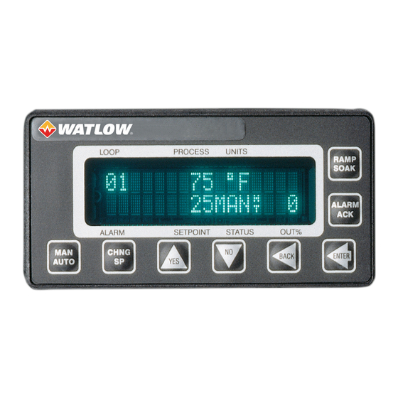
Page 49: Front Panel
CLS200 Series User’s Guide Chapter 3: Using CLS200 Front Panel The CLS200 front panel provides a convenient interface with the controller. You can use the front panel keys to program and operate the CLS200. RAMP SOAK • Assigns and monitors profiles ALARM ACK •... - Page 50 CLS200 Series User’s Guide Chapter 3: Using CLS200 NOTE! Pressing the NO key on power up performs a NO-key reset. This procedure clears the RAM and sets the controller’s parameters to their default values. See NO-Key Reset on page 150.
-
Page 51: Displays
CLS200 Series User’s Guide Chapter 3: Using CLS200 Displays This section discusses the controller’s main displays: bar graph, single loop and job. Bar Graph Display On power up, the controller displays general symbolic information for up to eight loops. This screen is called the bar graph display. -
Page 52: Single Loop Display
CLS200 Series User’s Guide Chapter 3: Using CLS200 Table 3.2 explains the control status symbols on the bottom line of bar graph display. Additional symbols may appear with the ramp/soak option. (See Bar Graph Display on page 126.) Table 3.2 Control Status Symbols on the Bar Graph and Single Loop Displays —... -
Page 53: Alarm Displays
CLS200 Series User’s Guide Chapter 3: Using CLS200 Process Variable Engineering Units Loop Number or Name Cool Output Percentage 160˚F 180HEAT100 Heat Output ALARM Percentage Setpoint Control Status Figure 3.5 — Single Loop Display, Heat and Cool Outputs Enabled Navigating the Single Loop Display In the single loop display: •... -
Page 54: Figure 3.7 - Failed Sensor Alarm In The Single Loop Display
CLS200 Series User’s Guide Chapter 3: Using CLS200 T/C BREAK Failed Sensor 25MAN Description ALARM Alarm Code Figure 3.7 — Failed Sensor Alarm in the Single Loop Display Alarms that still exist but have been acknowledged are displayed on the Bar Graph display. A letter or symbol indicates the alarm condition. -
Page 55: System Alarms
When a system alarm occurs, the global alarm output turns on and an alarm message appears on the display. The message continues to be displayed until the error condition is removed and the alarm is acknowledged. The CLS200 can display the following system alarms: • BATTERY DEAD See Battery Dead on page 143. -
Page 56: Changing The Setpoint
CLS200 Series User’s Guide Chapter 3: Using CLS200 If the job was loaded using digital inputs, the display shows: JOB 3 RUNNING REMOTELY LOADED ALARM Changing the Setpoint Select the single loop display for the loop you want to change. Press CHNG SP. This display... -
Page 57: Manual And Automatic Control
5. Press BACK at any time to discard your changes and return to single loop display. Autotuning a Loop Autotuning is a process by which a controller determines the correct PID parameters for optimum control. This section explains how to autotune the CLS200. - Page 58 CLS200 Series User’s Guide Chapter 3: Using CLS200 Prerequisites Before autotuning the controller, it must be installed with control and sensor circuitry and the thermal load in place. It must be safe to operate the thermal system, and the approximate desired operating temperature (setpoint) must be known.
-
Page 59: Using Alarms
When tuning is completed the control status indicator changes to AUTO. 9. Adjust the setpoint to the desired temperature. 10. Restore the INPUT FILTER parameter to its original value. Using Alarms The CLS200 has three main types of alarms: • Failed sensor alarms • Process alarms • System alarms Alarm Delay You can set the controller to delay normal alarm detection and alarm reporting. - Page 60 CLS200 Series User’s Guide Chapter 3: Using CLS200 What Happens if a Failed Sensor Alarm Occurs? If a failed sensor alarm occurs: • The controller switches to manual mode at the output power set with the SENSOR FAIL HT OUTPUT and SENSOR FAIL CL OUTPUT parameters in the SETUP LOOP OUTPUTS menu.
-
Page 61: Process Alarms
CONTROL PARAMS menu. • Connect the digital input to the dc common terminal on the controller. Process Alarms The CLS200 has four process alarms, each of which you can configure separately for each loop: • Low process alarm • High process alarm •... -
Page 62: Figure 3.9 - Activation And Deactivation Of Process Alarms
CLS200 Series User’s Guide Chapter 3: Using CLS200 Alarm Type: Control or Alarm You can configure each process alarm as either a control or alarm. • Alarm configuration provides traditional alarm functionality: The operator must acknowledge the alarm message on the controller display, a latching global alarm is activated, and the alarm can activate a user-specified, non-latching alarm output. -
Page 63: Global Alarm
CLS200 Series User’s Guide Chapter 3: Using CLS200 Global Alarm The CLS200 comes equipped with a global alarm output. The global output is activated if one or more of the following conditions occurs: • A system alarm occurs, or • A failed sensor alarm occurs and is unacknowledged, or •... -
Page 64: Chapter 4: Setup-64
• Description of controller parameters If you have not set up a CLS200 series controller before, or if you do not know what values to enter, please read Chapter 7: Tuning and Control, which contains PID tuning constants and useful starting values. - Page 65 CLS200 Series User’s Guide Chapter 4: Setup 3. To select the appropriate menu: a. Press NO to move from one menu to the next. The menus wrap around; pressing NO continuously advances through the top level menus. b. Press YES to enter the displayed menu.
-
Page 66: Standard Menus
ERR CHECK? INPUT FILTER? COOL OUTPUT AC LINE FREQ? LIMIT? DIG OUT POLARITY COOL OUTPUT ON ALARM? LIMIT TIME? CLS 200 SENSOR FAIL [FIRMWARE INFO] CL OUTPUT? COOL T/C BRK OUT AVG? COOL OUTPUT? Figure 4.1 — CLS200 Menu Tree... -
Page 67: Setup Global Parameters Menu
CLS200 Series User’s Guide Chapter 4: Setup Setup Global Parameters Menu SETUP GLOBAL PARAMETERS ALARM Table 4.1 shows the parameters available in this menu. Table 4.1 Global Parameters — PARAMETER DEFAULT VALUE LOAD SETUP FROM JOB? SAVE SETUP TO JOB? -
Page 68: Save Setup To Job
CLS200 Series User’s Guide Chapter 4: Setup LOAD SETUP FROM JOB? 1 ALARM Selectable values: 1 to 8 The following parameters are loaded for each loop as part of a job: • PID constants, filter settings, setpoints and spread values. -
Page 69: Job Select Digital Inputs Active
CLS200 Series User’s Guide Chapter 4: Setup JOB SELECT DIG INPUTS? NONE ALARM Selectable values: 1, 2 or 3 inputs, or NONE. These choices have the following effect: Table 4.2 Job Select Inputs — SETTING ENABLES Jobs 1-2 Jobs 1-4... -
Page 70: Output Override Digital Input
CLS200 Series User’s Guide Chapter 4: Setup Output Override Digital Input To enable the output override feature, select a digital input. When the specified input is activated, the controller sets all loops to manual mode at the output levels specified at the SENSOR FAIL HT OUTPUT and SENSOR FAIL CL OUTPUT parameters in the SETUP LOOP OUTPUTS menu. -
Page 71: Keyboard Lock Status
CLS200 Series User’s Guide Chapter 4: Setup Keyboard Lock Status Set this parameter to ON to disable the CHNG SP, MAN/AUTO, and RAMP/SOAK keys on the keypad. If the keys are disabled, pressing them has no effect. If you want to use these functions, turn off the keyboard lock. -
Page 72: Controller Address
RTU), ANA (Anafaze), AB (Allen Bradley). ® Communications Error Checking If you selected the ANA or AB communications protocol, set the data check algorithm for CLS200 communications. CRC (Cyclic Redundancy Check) is a more secure error checking algorithm than BCC, but it requires more calculation time and slows communications. -
Page 73: Ac Line Frequency
CLS200 Series User’s Guide Chapter 4: Setup COMMUNICATIONS ERR CHECK ? BCC ALARM Selectable values: BCC or CRC. AC Line Frequency Specify the ac line frequency. Since the controller reduces the effect of power line noise on the analog measurement by integrating the signal over the period of the ac line frequency, the controller must know the frequency of power in use. -
Page 74: Setup Loop Input Menu
CLS200 Series User’s Guide Chapter 4: Setup Table 4.4 Firmware Option Codes — FIRMWARE OPTION DECRIPTION (none) Standard Firmware Enhanced Features Option Ramp/Soak Option NOTE! If the EPROM information does not match this description, the EPROM probably contains a custom program. Custom programs may not work as described in this manual. -
Page 75: Input Type
17 on a sixteen-channel controller). 01 INPUT TYPE ? J T/C ALARM Selectable values: See Table 4.6. Table 4.6 CLS200 Input Types and Ranges — INPUT TYPE INPUT RANGE J T/C -350 to 1,400˚ F (-212 to 760˚ C) K T/C -450 to 2,500˚... -
Page 76: Loop Name
CLS200 Series User’s Guide Chapter 4: Setup Loop Name Assign a two-character name to the loop. This name is shown on the single loop display in place of the loop number. 01 LOOP NAME ? ALARM Selectable values: 0 to 9, A to Z, %, /, ° (degree symbol). -
Page 77: Reversed T/C Detection
CLS200 Series User’s Guide Chapter 4: Setup Table 4.8 Input Reading Offset — OFFSET RANGE TYPE OF SENSOR ˚F ˚C RTD2 -300 to +300 -300 to +300 RTD1 -300.0 to +300.0 -300.0 to +300.0 -300 to +76 -300 to +300... -
Page 78: Figure 4.2 - Two Points Determine Process Variable Conversion
CLS200 Series User’s Guide Chapter 4: Setup The scaling function is defined by two points on a conversion line. This line relates the process variable (PV) to the input signal. The engineering units of the process variable can be any units—the graph in Figure 4.2 shows PSI as an example. -
Page 79: Table 4.9 - Display Formats
CLS200 Series User’s Guide Chapter 4: Setup Display Format Select a display format for a linear or pulse input. Choose a format appropriate for the input range and sensor accuracy. 01 DISP FORMAT ? -999 3000 ALARM Selectable values: The controller has several available display formats, as shown in Table 4.9. The table also shows the maximum and minimum process variable for each display format. -
Page 80: Input Filter
CLS200 Series User’s Guide Chapter 4: Setup Low Process Variable Set a low process variable for input scaling purposes. The low process variable and the low reading (LO RDG) together define one of the points on the linear scaling function’s conversion line. Set LO PV to the value you want displayed when the signal is at the level set for the low reading (LO RDG). -
Page 81: Setup Loop Control Parameters Menu
CLS200 Series User’s Guide Chapter 4: Setup Setup Loop Control Parameters Menu Use the SETUP LOOP CONTROL PARAMS menu to adjust heat and cool control parameters, including: • Proportional band (PB, or gain), integral (TI or reset), and derivative (TD, or rate) settings •... -
Page 82: Heat Or Cool Control Pb
CLS200 Series User’s Guide Chapter 4: Setup Heat or Cool Control PB Set the proportional band (also known as gain). A larger value yields less proportional action for a given deviation from setpoint. 01 HEAT CONTROL ALARM Selectable values: Dependent upon sensor type. -
Page 83: Heat Or Cool Output Filter
CLS200 Series User’s Guide Chapter 4: Setup Heat or Cool Output Filter Dampen the response of the heat or cool output. The output responds to a step change by going to approximately 2/3 of its final value within the number of scans you set here. A larger value results in a slower, or more dampened, response to changes in the process variable. -
Page 84: Setup Loop Outputs Menu
CLS200 Series User’s Guide Chapter 4: Setup Setup Loop Outputs Menu Use the SETUP LOOP OUTPUTS menu to: • Enable or disable outputs • Set output type • Set cycle time for time proportioning outputs • Enter Serial DAC parameters (for Serial DAC outputs) •... -
Page 85: Enable Or Disable Heat Or Cool Outputs
CLS200 Series User’s Guide Chapter 4: Setup Enable or Disable Heat or Cool Outputs Enable or disable the heat or cool output for the loop. If you want the loop to have a control output, you must enable at least one output. You can also disable a heat or cool control output and use the output for something else, such as an alarm. -
Page 86: Heat Or Cool Cycle Time
CLS200 Series User’s Guide Chapter 4: Setup Heat or Cool Cycle Time Set the cycle time for time proportioning outputs. This parameter appears only if the heat or cool output type for the loop is set to time proportioning (TP). -
Page 87: Heat Or Cool Output Action
CLS200 Series User’s Guide Chapter 4: Setup 01 SDAC HI VALUE? 10.00 VDC ALARM Selectable values: 0.10 to 10.00 VDC or 0.10 to 20.00 MA. This value must be greater than the SDAC LO VALUE. Heat or Cool Output Action Select the control action for the output. -
Page 88: Sensor Fail Heat Or Cool Output
CLS200 Series User’s Guide Chapter 4: Setup Sensor Fail Heat or Cool Output When a sensor fail alarm occurs or when the OUTPUT OVERRIDE DIG INPUT becomes active on a loop that is in automatic control, that loop goes to manual control at the percent power output set here. -
Page 89: Setup Loop Alarms Menu
CLS200 Series User’s Guide Chapter 4: Setup Linear Curve 1 Curve 2 PID Calculation Figure 4.4 — Linear and Nonlinear Outputs If curve 1 or 2 is selected, a PID calculation results in a lower actual output level than the linear output requires. -
Page 90: High Process Alarm Setpoint
CLS200 Series User’s Guide Chapter 4: Setup Table 4.13 Setup Loop Alarms — PARAMETER DEFAULT VALUE HI PROC ALARM SETPT? 1000 HI PROC ALARM TYPE? HI PROC ALARM OUTPUT? NONE DEV ALARM VALUE? HI DEV ALARM TYPE? HI DEV ALARM OUTPUT? -
Page 91: Deviation Alarm Value
CLS200 Series User’s Guide Chapter 4: Setup Selectable values: NONE, or any output from 1 to 34 not enabled for closed-loop control or for the Serial DAC clock. Deviation Alarm Value Set the deviation from setpoint at which the high and low deviation alarms occur. -
Page 92: Low Deviation Alarm Output Number
CLS200 Series User’s Guide Chapter 4: Setup Low Deviation Alarm Output Number Choose a digital output to activate when the low deviation alarm occurs, if desired. 01 LO DEV ALARM OUTPUT ? NONE ALARM Selectable values: NONE, or any output from 1 to 34 not enabled for closed-loop control or for the Serial DAC clock. -
Page 93: Alarm Delay
CLS200 Series User’s Guide Chapter 4: Setup 01 ALARM DEAD- BAND ? ALARM Selectable values: 0 to 255, 25.5, 2.55, .255 or .0255, depending on the INPUT TYPE and DISP FORMAT settings. Alarm Delay Set a loop alarm delay. This parameter delays failed sensor, process and deviation alarms until the alarm condition has been continuously present for longer than the alarm delay time. -
Page 94: Digital Inputs
CLS200 Series User’s Guide Chapter 4: Setup Digital Inputs View the logic state of the eight digital inputs as H (high) meaning the input is not pulled low, or L (low) meaning the input is connected to the controller common. -
Page 95: Keypad Test
CLS200 Series User’s Guide Chapter 4: Setup Keypad Test Test the keypad. The test begins automatically when the screen appears. KEYPAD TEST QUIT = "NO"+"NO" ALARM • Press any key to test the keypad. The controller will display the name of the key you have pressed. -
Page 96: Chapter 5: Enhanced Features-96
Chapter 5: Enhanced Features This chapter explains five additional features for the CLS200 controller when enabled with enhanced features option firmware: • Process variable retransmit • Cascade control • Ratio control • Remote analog setpoint • Differential control... -
Page 97: Enhanced Features Menus
CLS200 Series User’s Guide Chapter 5: Enhanced Features Enhanced Features Menus SETUP SETUP SETUP SETUP SETUP SETUP SETUP SETUP MANUAL GLOBAL LOOP LOOP CONTROL LOOP LOOP PV LOOP LOOP RATIO LOOP PARAMETERS INPUTS PARAMETERS OUTPUTS RETRANSMIT CASCADE CONTROL ALARMS TEST... -
Page 98: Process Variable Retransmit
CLS200 Series User’s Guide Chapter 5: Enhanced Features Process Variable Retransmit The process variable retransmit feature retransmits the process signal of one loop (primary) via the control output of another loop (secondary). This signal is linear and proportional to the engineering units of the primary loop input. - Page 99 CLS200 Series User’s Guide Chapter 5: Enhanced Features Minimum Input Enter the lowest value of the process variable to be retransmitted. This value is expressed in the same engineering units as the input loop. If the process variable falls below the minimum, the output will stay at the minimum value.
-
Page 100: Process Variable Retransmit Example: Data Logging
Selectable values: 0 to 100%. Process Variable Retransmit Example: Data Logging The CLS200 controls the temperature of a furnace. The thermocouple in one of the zones is connected to the controller and is used for closed-loop PID control. An analog recorder data logging system is also in place, and a recording of the process temperature is required. -
Page 101: Figure 5.3 - Application Using Process Variable Retransmit
CLS200 Series User’s Guide Chapter 5: Enhanced Features Loop 1 Input Process Loop 1 PID Output Variable Loop 2 PID Output Furnace CLS200 Heater Serial Power Controller To Data Logger Figure 5.3 — Application Using Process Variable Retransmit To set up this application, you would do the following: 1. -
Page 102: Cascade Control
In this example, the data logger requires an analog input of 4 to 20mA. • The CLS200 Series controllers must be used with a Watlow Serial DAC. Consult Chapter 4: Setup for information on setting up the other options of the controller. -
Page 103: Setup Loop Cascade Menu
Some applications, such as aluminum casting, use two-zone cascade control where the primary output is used for the primary heat control and the cascaded output is used for boost heat. The CLS200 allows you to use the primary heat output for both control and for determining the setpoint of the secondary loop. - Page 104 CLS200 Series User’s Guide Chapter 5: Enhanced Features Base Setpoint Enter the setpoint that corresponds to 0% (heat and cool) output from the primary loop (PRIM. LOOP). This value is expressed in the same engineering units as the secondary loop’s process variable.
-
Page 105: Cascade Control Example: Water Tank
CLS200 Series User’s Guide Chapter 5: Enhanced Features Cool Span Enter the multiplier to apply to the primary loop cool out-put percentage. 02 CASCADE CL SPAN? +9999 ALARM Selectable values: -9999 to +9999. Cascade Control Example: Water Tank A tank of water has an inner and outer thermocouple. The outer thermocouple is located in the center of the water. -
Page 106: Table 5.2 - Application Example: Setting Up Cascade Control
CLS200 Series User’s Guide Chapter 5: Enhanced Features Table 5.2 Application Example: Setting Up Cascade Control — DISPLAY USER INPUT SETUP LOOP 02 Press YES to set up the cascade parameters with loop 2 as CASCADE? the secondary loop. ALARM 02 CASCADE Enter 01 for loop 1 process variable. -
Page 107: Figure 5.6 - Secondary Loop Setpoint Related To Primary Loop Output
CLS200 Series User’s Guide Chapter 5: Enhanced Features 4. To complete the cascade setup, both loop 1 and loop 2 must be configured for inputs, outputs, and alarms. In addition, the PID parameters of loop 1 must be tuned to produce the desired effect for the application on the setpoint of loop 2. -
Page 108: Ratio Control
CLS200 Series User’s Guide Chapter 5: Enhanced Features Ratio Control Ratio control allows the process variable of one loop (master loop), multiplied by a ratio, to be the setpoint of another loop (ratio loop). You can assign any process variable to determine the setpoint of a ratio loop. - Page 109 CLS200 Series User’s Guide Chapter 5: Enhanced Features Master Loop Enter the master loop which will provide the output to the internal controller setpoint calculation for the ratio loop setpoint. 02 RATIO CONTROL MSTR LOOP? NONE ALARM Selectable values: Any loop except the loop currently selected (in this case, loop 02). Choose NONE for no ratio control.
-
Page 110: Ratio Control Example: Diluting Koh
O is 10 gallons per second (gps), so the KOH should flow at 5 gps. Separate pipes for each chemical feed a common pipe. The flow rate of each feeder pipe is measured by a CLS200, with H O flow as process variable 1 and KOH flow as process variable 2. -
Page 111: Table 5.3 - Application Example: Setting Up Ratio Control
CLS200 Series User’s Guide Chapter 5: Enhanced Features Table 5.3 Application Example: Setting Up Ratio Control — DISPLAY USER INPUT SETUP LOOP 02 Press YES to set up the ratio control parameters or loop 02. RATIO CONTROL? ALARM 02 RATIO CONTROL Assign loop 01 as the master loop. -
Page 112: Remote Analog Setpoint
For example, a 0 to 5VDC signal representing 0 to 300°F will be used as a remote setpoint input to the CLS200. The input signal will be received on loop 1 with the control being performed on loop 2. Note that proper scaling resistors must be installed on the input of loop 1 to allow it to accept a 0 to 5VDC input. -
Page 113: Differential Control
CLS200 Series User’s Guide Chapter 5: Enhanced Features DISPLAY USER INPUT Enter the maximum ratio loop setpoint. For this example, we 02 RATIO CONTROL will use 300.0˚ F as a maximum. MAX SP? 300.0 Press ENTER. ALARM Enter the control ratio, which is the multiple applied to the 02 RATIO CONTROL master process variable. -
Page 114: Table 5.5 - Application Example: Setting Up Differential Control
CLS200 Series User’s Guide Chapter 5: Enhanced Features To set up this application, you would do the following: 1. Change the display to loop 2, and then enter the setup parameters. Go to the first screen in Table 5.5. 2. Follow the steps in Table 5.5 to configure the process variable retransmit option. -
Page 115: Chapter 6: Ramp/Soak-115
Chapter 6: Ramp/Soak This chapter covers setup and operation of ramp/soak profiles in CLS200 series controllers. These features are available in controllers that have the optional ramp/soak firmware installed. The ramp/soak feature turns your controller into a powerful and flexible batch controller. -
Page 116: Features
• Fast setup for similar profiles: Set up one profile, then copy it and alter it to set up the rest. • External reset: Select a digital input you can use to hold a profile in the “start” state and restart it. Table 6.1 summarizes the ramp/soak features of the CLS200. Table 6.1 Ramp/Soak Specifications —... -
Page 117: Ramp/Soak Menus
CLS200 Series User’s Guide Chapter 6: Ramp/Soak Ramp/Soak Menus The SETUP R/S PROFILES menu appears between the SETUP LOOP ALARMS and MANUAL I/O TEST menus. Figure 6.2 shows the ramp/soak setup menu tree. *See Process Variable Retransmit on page 98. -
Page 118: Setup Global Parameters Menu
CLS200 Series User’s Guide Chapter 6: Ramp/Soak Setup Global Parameters Menu With the Ramp and Soak option, an additional menu appears on the SETUP GLOBAL PARAMETERS menu. Ramp/Soak Time Base The RAMP/SOAK TIME BASE parameter is in the SETUP GLOBAL PARAMETERS menu. -
Page 119: Tolerance Alarm Time
CLS200 Series User’s Guide Chapter 6: Ramp/Soak Tolerance Alarm Time Set a limit on how long the process variable can be outside the tolerance set for the segment before the tolerance alarm occurs.If the process variable does not return within the tolerance, the tolerance alarm will recur after the tolerance alarm time elapses again. -
Page 120: External Reset Input Number
CLS200 Series User’s Guide Chapter 6: Ramp/Soak Ready Event Output Press NO to increment the output number. Press YES to set the event state to ON or OFF. This parameter appears only if you answered YES to READY SEGMENT EDIT EVENTS? -
Page 121: Segment Setpoint
CLS200 Series User’s Guide Chapter 6: Ramp/Soak Segment Setpoint Enter the ending setpoint for the segment you are editing. For a ramp, the setpoint changes steadily over the segment time from the end setpoint of the previous segment to the value set here. For a soak, set the value here equal to the end setpoint of the previous segment. -
Page 122: Edit Segment Triggers
CLS200 Series User’s Guide Chapter 6: Ramp/Soak Segment Events Output States Assign a state to the event. At the end of the segment, the output goes to the state you assign here. This parameter appears only if you answered YES to EDIT SEG EVENTS? -
Page 123: Segment Tolerance
CLS200 Series User’s Guide Chapter 6: Ramp/Soak Trigger Latch Status Choose whether the trigger is latched or unlatched. • A latched trigger is checked once, at the beginning of a segment. • An unlatched trigger is checked constantly while a a segment is running. If an unlatched trigger becomes false, the segment timer stops and the loop goes into trigger wait state. -
Page 124: Last Segment
CLS200 Series User’s Guide Chapter 6: Ramp/Soak Last Segment Specify whether the current segment is the last one in the profile. A SEGMENT 01 LAST SEGMENT? NO ALARM Selectable values: NO or YES. Repeat Cycles Set the number of times you want a profile to repeat or cycle. -
Page 125: Using Ramp/Soak
CLS200 Series User’s Guide Chapter 6: Ramp/Soak Using Ramp/Soak This section explains how to assign a profile to a loop, how to put a profile in RUN or HOLD mode, how to reset a profile, and how to display profile statistics. Figure 6.4 shows the ramp/soak screens. -
Page 126: Table 6.5 - Ramp/Soak Control Status Symbols
CLS200 Series User’s Guide Chapter 6: Ramp/Soak This is the single loop display when a profile is running. If a tolerance alarm occurs, the controller displays a flashing T in the alarm symbol position. Process Variable Engineering Units Loop Number ˚F... -
Page 127: Assigning A Profile To A Loop
CLS200 Series User’s Guide Chapter 6: Ramp/Soak Cycle Number Display From the single loop display, press the RAMP/SOAK key twice. This screen displays the number of times the profile has run out of the total number of cycles. In this example, the ramp/soak profile is on the 10th of 15 cycles to be performed. -
Page 128: Running A Profile
CLS200 Series User’s Guide Chapter 6: Ramp/Soak 3. Press the NO key. You will see the RESET PROFILE parameter. See Resetting a Profile on page 130. 4. Press YES then ENTER to reset the profile. You will see the ASSIGN PROFILE parameter. -
Page 129: Responding To A Tolerance Alarm
CLS200 Series User’s Guide Chapter 6: Ramp/Soak Table 6.6 Ramp/Soak Profile Modes — CURRENT MODE AVAILABLE MODE DESCRIPTION STRT Begin running the assigned profile. Continue from user-selected hold. The profile runs from the point when you put the profile in HOLD mode. -
Page 130: Resetting A Profile
CLS200 Series User’s Guide Chapter 6: Ramp/Soak If the process variable returns within the segment tolerance before the tolerance alarm time elapses, the profile returns to RUN mode and the tolerance alarm timer resets. The following occurs if the profile remains out of tolerance for longer than the tolerance alarm time: •... -
Page 131: Chapter 7: Turning And Control-131
This chapter describes the different methods of control available with the CLS200. This chapter covers control algorithms, control methods, PID control, starting PID values and tuning instructions to help appropriately set control parameters in the CLS200 system. For more information on PID control, consult the Watlow Practical Guide to PID. -
Page 132: Proportional Control
CLS200 Series User’s Guide Chapter 7: Turning and Control Heat Off Heat Off Setpoint Process Heat On ˚ 1,000 Variable Setpoint - Spread Output ˚ Figure 7.1 — On/Off Control Proportional Control Proportional control eliminates cycling by increasing or decreasing the output proportionally with the process variable’s deviation from the setpoint. -
Page 133: Proportional And Integral Control
CLS200 Series User’s Guide Chapter 7: Turning and Control Proportional and Integral Control With proportional and integral control, the integral term corrects for offset by repeating the proportional band’s error correction until there is no error. For example, if a process tends to settle about 5°F below the setpoint, appropriate integral control brings it to the desired setting by gradually... -
Page 134: Heat And Cool Outputs
CLS200 Series User’s Guide Chapter 7: Turning and Control Heat and Cool Outputs Each loop may have one or two outputs. Often a heater is controlled according to the feedback from a thermocouple, in which case only one output is needed. -
Page 135: Output Filter
CLS200 Series User’s Guide Chapter 7: Turning and Control Distributed Zero Crossing (DZC) With DZC outputs, the PID algorithm calculates an output between 0 and 100%, but the output is distributed on a variable time base. For each ac line cycle, the controller decides whether the power should be on or off. -
Page 136: Setting Up And Tuning Pid Loops
CLS200 Series User’s Guide Chapter 7: Turning and Control Setting Up and Tuning PID Loops After installing your control system, tune each control loop and then set the loop to automatic control. When tuning a loop, choose PID parameters that will best control the process. This section gives PID values for a variety of heating and cooling applications. -
Page 137: Derivative Settings
CLS200 Series User’s Guide Chapter 7: Turning and Control Integral Term and Reset Settings Table 7.2 — INTEGRAL RESET INTEGRAL RESET (SECONDS/REPEAT) (REPEATS/MINUTE) (SECONDS/REPEAT) (REPEATS/MINUTE) 0.28 0.25 0.22 0.66 0.20 0.50 0.15 0.40 0.12 0.33 0.10 As a general rule, use 60, 120, 180 or 240 as a starting value for the integral. -
Page 138: General Pid Constants By Application
CLS200 Series User’s Guide Chapter 7: Turning and Control General PID Constants by Application This section gives PID values for many applications. They are useful as control values or as starting points for PID tuning. Proportional Band Only (P) Set the proportional band to 7% of the setpoint. (Example: Setpoint set to 450, proportional band set to 31). -
Page 139: Chapter 8: Troubleshooting And Reconfiguring-139
If the troubleshooting procedures in this chapter do not solve your system’s problems, call Application Engineering for additional troubleshooting help. If you need to return the unit to Watlow for testing and repair, Customer Service will issue you an RMA number. See Return Material Authorization (RMA) on page 3. -
Page 140: Troubleshooting Controllers
CLS200 Series User’s Guide Chapter 8: Troubleshooting and Reconfiguring Troubleshooting Controllers A problem may be indicated by one or more of several types of symptoms: • A process or deviation alarm • A failed sensor alarm • A system alarm •... -
Page 141: Failed Sensor Alarms
CLS200 Series User’s Guide Chapter 8: Troubleshooting and Reconfiguring In a heating application, a high process alarm setpoint or high deviation alarm may indicate one of the following: • The setpoint and high process alarm setpoint have been lowered and the system has not had time to cool to within the new alarm limit. -
Page 142: System Alarms
Replace the EPROM. See Replacing the CLS200 display is not lit No EPROM or bad EPROM EPROM on page 150. Return the CLS200 for repair. See Return CLS200 damaged or failed Material Authorization (RMA) on page 3. Keypad is locked See Keys Do Not Respond on page 145. -
Page 143: Corrective And Diagnostic Procedures
Return Material Authorization (RMA) on page 3. Battery Dead The dead battery alarm indicates that the CLS200 battery is not functioning correctly or has low power or no power. If this alarm occurs, parameters have reset to the factory default settings. -
Page 144: Ambient Warning
Return Material Authorization (RMA) on page 3. H/W Ambient Failure The hardware ambient failure alarm indicates that the ambient sensor in the CLS200 is reporting that the temperature around the controller is outside of the acceptable range of 0 to 50°C. This error can also occur when there is a hardware failure. -
Page 145: H/W Gain Or Offset Failure
Before replacing the controller, troubleshoot for noise and ground loops. Keys Do Not Respond If the CLS200 seems to function but the MAN/AUTO, CHNG SP, ALARM ACK, and RAMP/SOAK keys do not respond when you press them, the keypad is probably locked. Unlock the keypad according to the instructions in Keyboard Lock Status on page 71. -
Page 146: Earth Grounding
Measure from either positive or negative thermocouple lead to ac ground. AC voltage above 2VAC may indicate the ground lead is not connected to the CLS200 TB2 ground terminal. -
Page 147: Checking Control Outputs
Testing Control Output Devices Connect the solid state relay (SSR) control terminals to the CLS200 control output and connect a light bulb (or other load that can easily be verified) to the output terminals on the SSR. Put the loop in manual mode and set the output to 100%. -
Page 148: Testing Digital Inputs
CLS200 Series User’s Guide Chapter 8: Troubleshooting and Reconfiguring 4. Connect the voltmeter’s common lead to the output terminal, and connect the voltmeter’s positive lead to the +5V terminal. 5. Restore power to the controller. 6. If you are testing a PID control output, use the MAN/AUTO key to turn the output on (100%) and off (0%). -
Page 149: Communications
CLS200 Series User’s Guide Chapter 8: Troubleshooting and Reconfiguring • You can also connect an oscilloscope to the transmit or receive line to see whether data is being sent or received. If the serial port does not appear to be working, the software setup may need to be modified or the hardware may need to be repaired or replaced. -
Page 150: No-Key Reset
Chapter 8: Troubleshooting and Reconfiguring User-Written Software You can request a communications specification from Watlow if you want to write your own software. Watlow will answer technical questions that arise during your software development process, but does not otherwise support user-developed or third-party software in any way. -
Page 151: Figure 8.1 - Remove Board Assembly From Case
CLS200 Series User’s Guide Chapter 8: Troubleshooting and Reconfiguring Figure 8.1 — Remove Board Assembly from Case 5. Unplug the front panel overlay ribbon cable from the connector on the processor board (the bottom one in the stack of two boards). -
Page 152: Removing Or Replacing The Battery
CLS200 Series User’s Guide Chapter 8: Troubleshooting and Reconfiguring 8. Locate the EPROM on the processor board. The EPROM is a 32-pin socketed chip that is labeled with the model, version and checksum. Figure 8.5 — EPROM Location 9. Remove the existing EPROM from its socket with an IC extraction tool or a jeweler’s flathead screwdriver. -
Page 153: Changing Communications
CLS200 Series User’s Guide Chapter 8: Troubleshooting and Reconfiguring slot unlatches and the battery holder comes off the module. 5. Remove the battery from the holder. 6. Follow local applicable recycling requirements for Coin Cell Lithium type BR-1632 Battery. Figure 8.7 — Battery-Backed RAM Module on the Processor Board To replace the battery, if desired: 1. -
Page 154: Scaling Resistors
7. Reassemble the controller. Scaling Resistors Resistors are installed for all inputs on the CLS200. Inputs with signal ranges between -10 and +60mV use 0Ω resistors in the RC position only. All other input signals require special input scaling resistors. -
Page 155: Controllers
CLS200 Series User’s Guide Chapter 8: Troubleshooting and Reconfiguring Figure 8.9 shows the input circuit for one differential, analog input. See Current Inputs to Four-Loop and Eight-Loop Controllers on page 155 through RTDs and Thermistor Inputs to Four-Loop and Eight-Loop Controllers on page 156 for resistor values for voltage, current and RTD inputs. -
Page 156: Rtds And Thermistor Inputs To Four-Loop And Eight-Loop Controllers
CLS200 Series User’s Guide Chapter 8: Troubleshooting and Reconfiguring Table 8.9 Resistor Locations for Voltage Inputs to Four-Loop and Eight-Loop Controllers — RESISTOR LOCATIONS LOOP RTDs and Thermistor Inputs to Four-Loop and Eight-Loop Controllers Each RTD or thermistor input has three scaling resistors installed: one each at RA, RB and RC for the input. -
Page 157: Sixteen-Loop Input Circuit
CLS200 Series User’s Guide Chapter 8: Troubleshooting and Reconfiguring Sixteen-Loop Input Circuit Sixteen-loop controllers can accept single-ended thermocouple, mVDC, VDC and mA DC inputs. Unless ordered with special inputs, the controller accepts only signals within the standard range of -10 to 60mVDC. -
Page 158: Voltage Inputs To Sixteen-Loop Controllers
CLS200 Series User’s Guide Chapter 8: Troubleshooting and Reconfiguring Voltage Inputs to Sixteen-Loop Controllers Each voltage input has two scaling resistors installed: one at RC and one at RD for the input. The values of the resistors determines the input range. -
Page 159: Example 1: A 4-To-20Ma Sensor
Chapter 9: Linear Scaling Examples This chapter provides three linear scaling examples. The examples describe: • A pressure sensor generating a 4 to 20mA signal • A flow sensor generating a 0 to 5V signal • A pulse encoder generating 900 pulses per inch of movement Example 1: A 4-to-20mA Sensor Situation A pressure sensor that generates a 4 to 20mA signal is connected to the controller. -
Page 160: Example 2: A 0-To-5Vdc Sensor
CLS200 Series User’s Guide Chapter 9: Linear Scaling Examples Example 2: A 0-to-5VDC Sensor Situation A flow sensor connected to the controller measures the flow in a pipe. The sensor generates a 0 to 5V signal. The sensor’s output depends on its installation. Independent calibration measurements of the flow in the pipe indicate that the sensor generates 0.5V at three gallons per minute (GPM) and... -
Page 161: Example 3: A Pulse Encoder
A DISP FORMAT of -99.99 to 300.00 is appropriate. The input readings are as follows: • At 0Hz, the input reading will be 0.00 FPM. • At the maximum pulse rate of the CLS200 (2000Hz): 2000 pulses 60 seconds 1 inch 1 foot ×... -
Page 162: Chapter 10: Specifications-162
Chapter 10: Specifications This chapter contains specifications for the CLS200 series controllers and the TB50 terminal board. CLS200 System Specifications This section contains CLS200 series controller specifications for environmental specifications and physical dimensions, inputs, outputs, the serial interface and system power requirements. -
Page 163: Figure 10.1 - Cls200 Processor Module Dimensions
2.44 in. (62 mm) 1.98 in. (50 mm) 1.00 in. (25 mm) 10.00 in. (254 mm) Figure 10.2 — CLS200 Clearances with Straight SCSI Cable Table 10.5 Processor with Right Angle SCSI Cable — Length 9.0 inches 229 mm Width 3.80 inches... -
Page 164: Tb50 Physical Specifications
(62 mm) 1.98 in. (50 mm) 1.00 in. (25 mm) 9.00 in. (229 mm) Figure 10.3 — CLS200 Clearances with Right-Angle SCSI Cable Table 10.6 Processor Connections — Power Terminals (TB2) Captive screw cage clamp Power Wire Gauge (TB2 22 to 18 AWG (0.5 to 0.75 mm Power Terminal Torque (TB2) 4.4 to 5.3 in-lb. -
Page 165: Figure 10.4 - Tb50 Dimensions
CLS200 Series User’s Guide Chapter 10: Specifications 4.1 in. (104 mm) 0.92 in. (23 mm) 4.0 in. (102 mm) Figure 10.4 — TB50 Dimensions Table 10.8 TB50 Connections — SCSI Connector on Board SCSI-2 female Output Terminals Captive screw cage clamp Multiconductor cables: 24 AWG (0.2 mm... -
Page 166: Inputs
CLS200 Series User’s Guide Chapter 10: Specifications Table 10.10 TB50 with Right Angle SCSI Cable — Length 5.4 inches 137 mm Width 4.0 inches 102 mm Height DIN Rail Mounted 1.5 inches 37 mm 5.4 in. (137 mm) 4.0 in. -
Page 167: Table 10.12 - Pulse Inputs
CLS200 Series User’s Guide Chapter 10: Specifications PARAMETER DESCRIPTION 0.03% of full scale (60mV) at 25°C Accuracy 0.08% of full scale (60mV) at 0 to 50°C Calibration Automatic zero and full scale DC Common to Frame Ground Maximum Potential Thermocouple Break Detection Pulse type for upscale break detection 0 to 20mA (3Ω... -
Page 168: Outputs
CLS200 Series User’s Guide Chapter 10: Specifications Table 10.14 RTD Range and Resolution — ACCURACY* AT ACCURACY* AT MEASUREMENT 0 TO 50°C RANGE RANGE RESOLUTION 25°C AMBIENT NAME TEMPERATURE AMBIENT IN °F IN °C IN °C IN °C °F °C °F... -
Page 169: Table 10.17 - Digital Outputs Control / Alarm
Chapter 10: Specifications Analog Outputs Analog outputs may be accomplished by using Dual DAC or Serial DAC modules in conjunction with the digital outputs. Contact your supplier or Watlow for more information on these accessory products. Digital Outputs Table 10.17 Digital Outputs Control / Alarm —... -
Page 170: Table 10.20 - Reference Voltage Output (Power To Operate Bridge Circuit Sensors)
CLS200 Series User’s Guide Chapter 10: Specifications Table 10.20 Reference Voltage Output (Power to Operate Bridge Circuit Sensors) — PARAMETER DESCRIPTION Voltage 5VDC Maximum Current 10mA Table 10.21 —Serial Communication PARAMETER DESCRIPTION Type EIA/TIA-232 3-wire or EIA/TIA-485 4-wire Isolation None... - Page 171 Glossary Alarm Delay The lag time before an alarm is activated. See Alternating Current. Alternating Current (AC) An electric current that reverses at regular AC Line Frequency intervals, and alternates positive and negative The frequency of the AC power line measured in values.
- Page 172 CLS200 Series User’s Guide Autotune Closed Loop A feature that automatically sets temperature A control system that uses a sensor to measure control PID values to match a particular thermal a process variable and makes decisions based system. on that feedback.
- Page 173 Default Parameter Settings the risk of electrical shock. The values that the user adjustable parameters EIA/TIA have when a controller ships from Watlow or See Serial Communications. after the user programmed setting are cleared. Electrical Noise Derivative Control (D) See Noise.
- Page 174 Equivalent to a standard resistor-capacitor High Power (RC) filter. (Relative to the CLS200 power.) Any voltage Digital Adaptive Filter above 24VAC or VDC and any current level A filter that rejects high frequency input signal above 50mA AC or mA DC.
- Page 175 CLS200 Series User’s Guide Linearity The deviation in response from an expected or Infrared (IR) theoretical straight line value for instruments and A region of the electromagnetic spectrum transducers, also called linearity error. with wavelengths ranging from one to 1,000 microns.
- Page 176 CLS200 Series User’s Guide Output Type The form of PID control output, such as time NO-Key Reset proportioning, distributed zero crossing, Serial A method for resetting the controller’s memory. DAC or analog. Also the description of the electrical hardware that makes up the output.
- Page 177 CLS200 Series User’s Guide Proportional Control Resistance A control using only the P (proportional) value of Opposition to the flow of electric current, PID control. measured in ohms. Pulse Input Resistance Temperature Detector (RTD) Digital pulse signals from devices, such as A sensor that uses the resistance temperature optical encoders.
- Page 178 CLS200 Series User’s Guide Setpoint (SP) Thermocouple (T/C) The desired value programmed into a controller. A temperature sensing device made by joining For example, the temperature at which a two dissimilar metals. This junction produces an system is to be maintained.
- Page 179 CLS200 Series User’s Guide Zero Cross Action that provides output switching only at or near the zero-voltage crossing points of the ac sine wave.
- Page 180 Index low process alarm settings 92 messages 141, 142 AC LINE FREQ process 140 default value 67 resetting 141 description 73 restoring control after sensor failure 83 location 66 reversed thermocouple 77 AC Line Frequency 73 SCRs 38 A control status symbol 52 sensor fail percent output power 88 agency compliance setting up 61...
- Page 181 CALCULATING CHECKSUM 31 description 72 CANNOT LOAD JOB 68 location 66 CANNOT SAVE JOB 68 computer 148 CASCADE BASE SP Connecting TB50 to CLS200 31 description 104 control algorithms 131 location 97 on/off 131 CASCADE CL SPAN proportional, integral and derivative...
- Page 182 CLS200 Series User’s Guide control status 56 COOL RETRANS MIN OUT% symbols on display 52 description 99, 100 unexpected switches from automatic to location 97 manual 143 COOL T/C BRK OUT AVG COOL 52 description 88 COOL CONTROL FILTER location 66...
- Page 183 CLS200 Series User’s Guide specifications 169 environment testing 31, 94 controller 162 troubleshooting 147 EPROM will not turn on 27 checksum 73 wiring 36 replacing 150 DIG OUT POLARITY ON ALARM error checking 72 default value 67 external bridge circuit 34, 170...
- Page 184 CLS200 Series User’s Guide HEAT CONTROL OUTPUT location 97 default value 84 HEAT RETRANS MIN INP description 85 description 99 location 66 location 97 HEAT CONTROL PB HEAT RETRANS MIN OUT% default value 81 description 99 description 82 location 97...
- Page 185 CLS200 Series User’s Guide scaling resistors 154 wiring 25, 32 specifications 166 integral INPUT SCALING HI PV description 133 default value 74 guidelines for setting 136 description 79 setting a value 82 location 66 settings from other controllers 137 scaling parameters 77...
- Page 186 CLS200 Series User’s Guide display format 79 setting the output level 57 engineering units 76 MANUAL I/O TEST 93 scaling and calibration 158 location 66 scaling examples 159 parameters in menu 93 scaling parameters 77 M control status symbol 52...
- Page 187 CLS200 Series User’s Guide filter 83 high deviation 62 ramp/soak ready state 119 low deviation 62 setup parameters 84 outputs 61 solid state relays 38 setting up 61 specifications 168 PROCESS POWER DIGIN OVERRIDE DIG IN ACTIVE default value 67...
- Page 188 CLS200 Series User’s Guide specifications 116 RESET PROFILE 128 time base 118 RESET WITH DEFAULTS 150 time remaining 126 RestoreAuto parameter 61 tolerance 123 RESTORE PID DIGIN triggers 122 deafult value 81 RAMP/SOAK key 50 description 83 assigning profiles 127...
- Page 189 CLS200 Series User’s Guide SCSI cable 16, 18 and failed sensor alarm 60 clearance 21, 163, 164 SENSOR FAIL HT OUTPUT installing 31 and reversed thermocouple detection 71, 77 SDAC HI VALUE default value 84 default value 84 description 88...
- Page 190 CLS200 Series User’s Guide shutdown devices 18 to power encoders 35 single loop display 52 troubleshooting 147 control status symbols 52 T control status symbol 52 navigating 53 temperature ramp/soak symbols 125 incorrect on display 142, 145 when running ramp/soak proile 125...
- Page 191 CLS200 Series User’s Guide H/W OFFSET FAILURE 145 keypad 95, 142, 145 LOW POWER 143 process variable incorrect on display 142, sensor inputs 145 software 148 TB18 147 TB50 147 tolerance alarms 129 unexpected behavior 143 TUNE 52, 56, 59...
-
Page 192: Menu Structure-192
CLS200 Series User’s Guide Menu Structure SETUP GLOBAL PARAMETERS SETUP LOOP INPUT SETUP LOOP CONTORL PARAMS SETUP LOOP OUTPUTS SETUP LOOP ALARMS MANUAL I/O TEST LOAD SETUP FROM JOB INPUT TYPE HEAT CONTROL PB HEAT CONTROL OUTPUT HI PROC ALARM SETPT... -
Page 193: Declaration Of Conformity-193
CLS200 Series User’s Guide Declaration of Conformity... -
Page 194: How To Reach
电子邮件: info-cn@watlow.com Website: www.watlow.co.jp 网站: www.watlow.com Watlow Korea Co., Ltd. Watlow Electric Manufacturing Company (Shanghai) Co. Ltd. #2208, Hyundia KIC Building B, 70 Doosan-ro Greenland International Plaza Room 1306 Geumcheon-gu, Seoul 275-8 East Guoding Road, Yangpu District Republic of Korea...
Need help?
Do you have a question about the CLS200 and is the answer not in the manual?
Questions and answers