Sign In
Upload
Manuals
Brands
Watlow Manuals
Controller
Controller Series D8
User Manuals: Watlow Controller Series D8 Temperature
Manuals and User Guides for Watlow Controller Series D8 Temperature. We have
2
Watlow Controller Series D8 Temperature manuals available for free PDF download: User Manual, Specifications
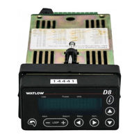
Watlow Controller Series D8 User Manual (179 pages)
Brand:
Watlow
| Category:
Controller
| Size: 13 MB
Table of Contents
Table of Contents
4
Chapter 1: System Overview
13
Manual Contents
13
Getting Started
14
Safety Symbols
14
Initial Inspection
14
Product Features
14
D8 Parts List
16
Table 1.1 - Ordering Options
16
Technical Description
17
Figure 1.1 - D8 Rear Views
17
D8 Cabling
18
Tb50
18
Safety
18
External Safety Devices
18
Figure 1.2 - D8 Front Panel
18
Figure 1.3 - TB50
18
Power-Fail Protection
19
Chapter 2: Installation
20
Typical Installation
20
Mounting Controller Components
21
Recommended Tools
21
Figure 2.1 - D8 System Components
21
Mounting the Controller
22
Figure 2.2 - Clearance with DB25 and SCSI Cable
22
Figure 2.3 - Clearance with Terminal Blocks (TB1 and TB18)
22
Figure 2.4 - Clearance with TB1 and SCSI Cable
22
Figure 2.5 - Mounting Bracket Clearance
23
Figure 2.6 - Panel Thickness and Cutout Size
23
Mounting the TB50
24
Figure 2.7 - Mounting the TB50
24
Figure 2.8 - TB50 Mounted on a DIN Rail (Front)
24
Figure 2.9 - TB50 Mounted on DIN Rail (Side)
24
Mounting the Power Supply
25
System Wiring
25
Figure 2.10 - Mounting a TB50 with Standoffs
25
Noise Suppression
26
Table 2.1 - Cable Recommendations
26
Wiring Recommendations
26
Ground Loops
27
Power Connections
28
Wiring the Power Supply
28
Figure 2.11 - Power Input with Mass Termination Option
28
Figure 2.12 - Power Input with Mass Termination Option
28
Table 2.2 - Power Connections
29
Connecting TB50 to the D8
30
Testing the System
30
TB50 or TB18 Test
30
Digital Output Test
30
Figure 2.13 - Power Connections with the D8 Power Supply
30
Digital Input Test
31
Sensor Wiring
31
Table 2.3 - Analog Input Connections Mass Termination Option
32
Input Wiring Recommendations
33
Table 2.4 - Analog Input Connections Screw Terminal Option
33
Thermocouple Connections
33
Figure 2.14 - Termocouple Connections
34
Figure 2.15 -RTD Connections
34
Figure 2.16 - Voltage Signal Connections
34
RTD Input Connections
34
Voltage Input Connections
34
Current Input Connections
35
Wiring Control and Digital I/O
35
Output Wiring Recommendations
35
Cable Tie Wraps
35
Digital Outputs
35
Figure 2.17 - Current Signal Connections
35
Table 2.5 - Digital Output States and Values Stored in the Controller
35
Figure 2.18 - Digital Output Wiring
36
Figure 2.19 - Sample Heat, Cool and Alarm Output Connections
37
Figure 2.20 - Output Connections Using External Power Supply
37
Digital Inputs
38
Figure 2.21 - TB50 Watchdog Timer Output
38
Figure 2.22 - TB18 Watchdog Timer Output
38
Table 2.6 - Digital Input States and Values Stored in the Controller
38
TB18 Connections
39
Figure 2.23 - Wiring Digital Inputs
39
Table 2.7 - TB18 Connections
39
TB50 Connections
40
Table 2.8 - TB50 Connections
40
Analog Outputs
41
Wiring the Dual DAC
41
Wiring the Serial DAC
41
Connecting the D8 to a Devicenet Network
41
Connector Type
41
Figure 2.24 - Devicenet™ Connector
41
Connector Pinout
42
Network Length
42
Baud Rate (Data Rate)
42
Figure 2.25 - J4 Devicenet™ Connector Pinout
42
Table 2.9 - Devicenet™ Connector
42
Table 2.10 - Maximum Network Speed
42
Node Address (MAC ID)
43
Status Indicators
43
Figure 2.26 - D8 Side with Rotary Switches
43
Table 2.11 - Module Status Indicator Light
44
Table 2.12 - Network Status Indicator Light
44
Chapter 3: Communicating by Devicenet
45
Accessing Data with a Devicenet Master
45
About the Electronic Data Sheet (EDS)
45
Setting Parameters Via Devicenet
45
Non-Numeric Settings
45
Bit-Wise Values
46
Decimal Placement for Numeric Values
46
Decimal Placement for Percentage Values
46
D8 Devicenet Overview
46
Table 3.1 - Implied Decimals by Input Type and Display Format
46
Addressing
47
Data Types
47
Master/Slave Connections
47
Table 3.2 - Address Components
47
Table 3.3 - Elementary Data Types
47
Devicenet Objects
48
Identity Object
48
Message Router Object
48
Table 3.4 - Identity Class and Services
48
Table 3.5 - Identity Instance Attributes
48
Table 3.6 - Message Router Class and Services
48
Devicenet Object
49
Assembly Object
49
Table 3.7 - Message Router Instance Attributes
49
Table 3.8 - Devicenet™ Class and Services
49
Table 3.9 - Devicenet™ Class Attributes
49
Table 3.10 - Devicenet™ Instance Attributes
49
Table 3.11 - Assembly Class and Services
50
Table 3.12 - Assembly Instance Attributes
50
Table 3.13 - Number of Bytes
50
Figure 3.1 - Four-Loop Produced Static Input
51
Figure 3.2 - Four-Loop Consumed Static Output
51
Figure 3.3 - Eight-Loop Produced Static Input
51
Connection Object
52
Figure 3.4 - Eight-Loop Consumed Static Output
52
Table 3.14 - Connection Class and Services
52
Table 3.15 - Connection Instance Attributes
52
Input Object
53
Table 3.16 - Input Class and Services
53
Table 3.17 - Input Class Attributes (Instance 0)
53
Table 3.18 - Input Instance Attributes (Instances 1 to 4 or 8)
53
Output Object
54
Table 3.19 - Output Class and Services
54
Table 3.20 - Output Class Attributes (Instance 0)
54
Table 3.21 - Output Instance Attributes (Instances 1 to 4 or 8)
54
Control Object
55
Table 3.22 - Control Class and Services
55
Table 3.23 - Control Class Attributes (Instance 0)
55
Table 3.24 - Control Instance Attributes (Instances 1 to 4 or 8)
55
Alarm Object
56
Table 3.25 - Alarm Class and Services
56
Table 3.26 - Alarm Class Attributes (Instance 0)
56
Table 3.27 - Alarm Instance Attributes (Instances 1 to 4 or 8)
56
PV Retransmit Object
57
Table 3.28 - PV Retransmit Class and Services
57
Table 3.29 - PV Retransmit Class Attributes (Instance 0)
57
Table 3.30 - PV Retransmit Instance Attributes (Instances 1 to 4 or 8)
57
Ratio Object
58
Cascade Object
58
Table 3.31 - Ratio Class and Services
58
Table 3.32 - Ratio Class Attributes (Instance 0)
58
Table 3.33 - Ratio Instance Attributes (Instances 1 to 4 or 8)
58
Table 3.34 - Cascade Class and Services
58
Global Object
59
Table 3.35 - Cascade Class Attributes (Instance 0)
59
Table 3.36 - Cascade Instance Attributes (Instances 1 to 4 or 8)
59
Table 3.37 - Global Class and Services
59
Table 3.38 - Global Class Attributes (Instance 0)
59
Table 3.39 - Global Instance Attributes (Instance 1)
59
Chapter 4: Operation and Setup
61
General Navigation Map
61
Figure 4.1 - General Navigation Map
61
Keypad
62
Displays
62
Loop Display
62
Figure 4.2 - Keypad Navigation
62
Figure 4.3 - Loop Display
62
Alarm Displays
63
Figure 4.4 - Loop Display with Alarm Code
63
Table 4.1 - Control Modes
63
Figure 4.5 - Display for Failed Sensor Alarm
64
Table 4.2 - Alarm Codes and Messages for Process and Failed Sensor Alarms
64
Job Display
65
Table 4.3 - System Alarm Messages
65
Changing the Set Point
66
How to Manually Change the Set Point
66
Other Methods of Changing the Set Point
66
Changing the Control Mode and Output Power
66
Accessing and Navigating the Setup Menus
67
How to Access the Setup Menus
67
How to Edit a Setup Parameter
67
Setting up Closed-Loop Control
68
Feedback
68
Control Algorithm
68
Control Output Signal Forms
68
Heat and Cool Outputs
68
How to Set up Closed-Loop Control
69
Setting up a Process Input
69
Input Scaling
69
Input Scaling Example: 4 to 20Ma Sensor
70
Figure 4.6 - Input Scaling
70
Input Scaling Example: 0 to 5VDC
71
Sensor
71
Table 4.4 - Input Readings
71
Table 4.5 - Scaling Values
71
Table 4.6 - Input Readings and Calculations
71
Autotuning
72
How Does Autotuning Work
72
Prerequisites
72
Table 4.7 - Scaling Values
72
How to Autotune a Loop
73
Setting up Alarms
73
Failed Sensor Alarms
73
Process Alarms
75
Global Alarm
76
Figure 4.7 - Activation and Deactivation of Process Alarms
76
Setting up Process Variable Retransmit
77
How to Set up Process Variable Retransmit
77
Process Variable Retransmit Example: Data Logging
77
Figure 4.8 - Application Using Process Variable Retransmit
78
Table 4.8 - Parameters Settings for Process Variable Retransmit Example
78
Setting up Cascade Control
79
How the Secondary Set Point Is Determined
79
Figure 4.9 - Secondary Set Point When Primary Loop Has Heat and Cool Outputs
79
Proportional-Only Control on the Primary Loop
80
How to Set up Cascade Control
80
Cascade Control Example: Water Tank
80
Figure 4.10 - Secondary Set Point When Primary Loop Has Heat Output Only
80
Figure 4.11 - Example Application Using Cascade Control
81
Table 4.9 - Parameter Settings for the Primary Loop in the Cascade Example
81
Table 4.10 - Parameter Settings for the Secondary Loop in the Cascade Example
81
Setting up Ratio Control
82
Figure 4.12 - Relationship of Secondary Loop
82
Figure 4.13 - Relationship between the Process Variable on the Master Loop and the Set Point of the Ratio
83
How to Set up Ratio Control
83
Ratio Control Example: Diluting KOH
83
Setting up Differential Control
84
How to Set up Differential Control
84
Figure 4.14 - Application Using Ratio Control
84
Table 4.11 - Ratio Control Settings for the Ratio Loop (Loop 2) in the Example
84
Differential Control Example: Thermoforming
85
Setting up Remote Analog Set Point
85
How to Set up a Remote Analog Set Point
85
Table 4.12 - Parameter Settings for the Ratio Loop (Loop 2) for the Example
85
Remote Analog Set Point Example: Changing a Set Point with a PLC
86
Table 4.13 - Parameters Settings for the Master Loop (Loop 1) in the Example
86
Table 4.14 - Parameter Settings for the Ratio Loop (Loop 2) in the Example
86
Chapter 5: Tuning and Control
87
Control Algorithms
87
On/Off Control
87
Proportional Control (P)
88
Figure 5.1 - On/Off Control
88
Figure 5.2 - Proportional Control
88
Proportional and Integral Control (PI)
89
Proportional, Integral and Derivative Control (PID)
89
Figure 5.3 - Proportional and Integral Control
89
Figure 5.4 - Proportional, Integral and Derivative Control
89
Heat and Cool Outputs
90
Setting up and Tuning PID Loops
90
Proportional Band Settings
90
Table 5.1 - Proportional Band Settings
90
Integral Settings
91
Derivative Settings
91
Table 5.2 - Integral Term and Reset Settings
91
Table 5.3 - Derivative Term Versus Rate
91
General PID Constants by Application
92
Proportional Band Only (P)
92
Proportional with Integral (PI)
92
Proportional and Integral with Derivative (PID)
92
Table 5.4 - General PID Constants
92
Control Outputs
93
Output Control Signals
93
Figure 5.5 - Time Proportioning and Distributed Zero Crossing Waveforms
93
Output Filter
94
Reverse and Direct Action
94
Chapter 6: Menu and Parameter Reference
95
Operator Parameters
95
01 Set Point
95
Figure 6.1 - Operator Parameter Navigation
95
Mode
96
Heat/Cool Output
96
Table 6.1 - Control Modes
96
Process Variable
97
Overview of the Setup Menus
97
Table 6.2 - D8 Setup Menus
97
Figure 6.2 - Setup Menus and Parameters
98
Global Setup Menu
99
Load Setup from Job
99
Save Setup as Job
100
BCD Job Load
100
BCD Job Load Logic
101
Table 6.3 - Values for BCD Job Load
101
Table 6.4 - Digital Input States Required to Load each Job
101
Mode Override
102
Mode Override Digital Input Active
102
Power up Alarm Delay
103
Power up Loop Mode
103
Table 6.5 - Power up Loop Modes
103
Default: 0
103
Values: See Table 6.5
103
Default: off
103
Keypad Lock
104
Thermocouple Short Alarm
104
AC Line Frequency
104
Digital Output Alarm Polarity
105
Mac ID
105
Baud Rate
105
Table 6.6 - Digital Output Alarm Polarity
105
Display Value Value
105
Off
105
Module LED
106
Network LED
106
Bus off Count
106
Model and Firmware Version
106
Input Menu
107
01 Input Type
107
Table 6.7 - Input Types and Ranges
107
Loop Name
108
01 Input Units
108
Table 6.8 - Characters for the Loop Name and Input Units Parameters
108
Calibration Offset
109
Reversed Thermocouple Detection
109
Table 6.9 - Calibration Offset Ranges
109
Display Format
110
Input Range High
110
Table 6.10 - Display Formats
110
Input High Signal
111
Input Range Low
111
Input Low Signal
111
Input Filter
112
Control Menu
112
Heat/Cool Proportional Band
113
Heat/Cool Integral
113
Table 6.11 - Proportional Band Values
113
Heat/Cool Derivative
114
Heat/Cool Manual Reset
114
Heat/Cool Filter
114
01 Hysteresis
115
Restore Automatic Mode
115
Table 6.12 - Values for the Control Hysteresis and Deviation Alarm Parameters
115
Output Menu
116
Heat/Cool Output Type
116
Table 6.13 - Heat and Cool Output Types
116
Heat/Cool Cycle Time
117
Heat/Cool SDAC Signal
117
Heat/Cool SDAC Low Signal
117
Heat/Cool SDAC High Signal
118
Heat/Cool Action
118
Heat/Cool Power Limit
118
Heat/Cool Power Limit Time
119
Sensor Fail Heat/Cool Output
119
Open Thermocouple Heat/Cool Output Average
120
Heat/Cool Output Curve
120
Figure 6.3 - Linear and Nonlinear Outputs
120
Alarms Menu
121
Alarm High Set Point
121
Alarm High Function
121
Alarm High Output
122
High Deviation Value
122
Table 6.14 - Alarm Functions
122
High Deviation Function
123
High Deviation Output
123
Low Deviation Value
123
Low Deviation Function
124
Low Deviation Output
124
Alarm Low Set Point
124
Alarm Low Function
125
Alarm Low Output
125
Alarm Hysteresis
125
01 Alarm Delay
126
Process Variable Retransmit Menu
126
Table 6.15 - Values for Alarm Hysteresis
126
Heat/Cool Output Retransmit
127
Heat/Cool Retransmit High Process Variable
127
Heat/Cool Retransmit Low Process Variable
127
Cascade Menu
128
Cascade Primary Loop
128
Cascade Low Set Point
128
Cascade High Set Point
129
Ratio Menu
129
Ratio Master Loop
129
Ratio Low Set Point
130
Ratio High Set Point
130
Control Ratio
130
Ratio Set Point Differential
131
I/O Tests Menu
131
Digital Inputs
131
Keypad Test
132
Display Test
132
Test Digital Output 1
132
Parameters Only Available Via Communications
133
Alarm Acknowledge
133
Alarm Enable
133
Table 6.16 - Bit Positions for Alarm Enable and Alarm Function
133
Alarm Function
134
Alarm Status
134
Ambient Sensor Reading
134
Table 6.17 - Bit Positions for Alarm Status and Alarm Acknowledge
134
Heat/Cool Output Action for Watchdog Inactivity Fault
135
Table 6.18 - System Status Bits
135
Table 6.19 - Devicenet™ Value for Watchdog Inactivity Fault
135
Chapter 7: Troubleshooting and Reconfiguring
136
When There Is a Problem
136
Troubleshooting the Controller
136
Process Alarms
137
Table 7.1 - Operator Response to Process Alarms
137
Ambient Warning
138
Failed Sensor Alarms
138
System Alarms
138
Other Behaviors
138
Table 7.2 - Other Symptoms
138
Reading the Devicenet Indicator Lights
139
Table 7.3 - Module Status Indicator States and Descriptions
139
Corrective and Diagnostic Procedures
140
Low Power
140
Battery Dead
140
Table 7.4 - Network Status Indicator Light
140
H/W Error: Gain or Offset
141
H/W Error: Ambient
141
Keys Do Not Work
142
Checking Analog Inputs
142
Earth Grounding
143
Testing Control Output Devices
144
Testing the TB18 and TB50
144
Testing Control and Digital Outputs
144
Testing Digital Inputs
144
Clearing the RAM
145
Replacing the EPROM
145
Figure 7.1 - Remove Board Assembly from Case
145
Figure 7.2 - Disconnect Keypad Ribbon Cable from Processor Board
146
Figure 7.3 - Unlatch Boards from Carrier
146
Figure 7.4 - Remove the Standoffs
146
Removing or Replacing the Battery
147
Figure 7.5 - EPROM Location
147
Figure 7.6 - Remove EPROM
147
Scaling Resistors
148
Input Circuit
148
Figure 7.7 - Battery-Backed RAM Module on the Processor Board
148
Current Inputs
149
Voltage Inputs
149
Figure 7.8 - Input Circuit
149
Table 7.5 - Resistor Values for Current Inputs
149
Table 7.6 - Resistor Locations for Current Inputs
149
Table 7.7 - Resistor Values for Voltage Inputs
149
RTD Inputs
150
Table 7.8 - Resistor Locations for Voltage Inputs
150
Table 7.9 - Resistor Locations for RTD Inputs
150
Scaling and Calibration
151
Chapter 8: Specifications
153
System Specifications
153
Physical Specifications
153
Table 8.1 - Agency Approvals / Compliance
153
Table 8.2 - Environmental Specifications
153
Figure 8.1 - D8 Module Dimensions Without Cables
154
Figure 8.2 - Clearance with DB25 and SCSI Cable
154
Table 8.3 - D8 with Standard SCSI
154
Figure 8.3 - Clearance with Terminal Blocks (TB1 & TB18)
155
Figure 8.4 - Clearance with TB1 and SCSI Cable
155
Table 8.4 - D8 Connections
155
Figure 8.5 - TB50 Dimensions
156
Table 8.5 - TB50 Physical Dimensions
156
Table 8.6 - TB50 Connections
156
Table 8.7 - TB50 with Straight SCSI
156
Inputs
157
Figure 8.6 - TB50 Dimensions with SCSI Cable
157
Table 8.8 - Analog Inputs
157
Table 8.9 - Thermocouple Range and Resolution
158
Table 8.10 - RTD Range and Resolution
158
Table 8.11 - Input Resistance for Voltage Inputs
158
Outputs
159
Table 8.12 - Digital Inputs
159
Table 8.13 - Digital Outputs Control / Alarm
159
Table 8.14 - 5VDC Output (Power to Operate Solid-State Relays)
160
Table 8.15 - Communications
160
Table 8.16 - D8 Power Requirements
160
Glossary
161
Index
169
Menu Structure
177
Declaration of Conformity
178
How to Reach Us
179
Advertisement
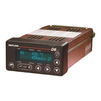
Watlow Controller Series D8 Specifications (4 pages)
Full Featured Controller in a 1/8 DIN Package with DeviceNet
Brand:
Watlow
| Category:
Controller
| Size: 0 MB
Advertisement
Related Products
Watlow DIN-A-MITE Style A
Watlow Din-a-mite
Watlow DIN-A-MITE Series
Watlow DIN-A-MITE C
Watlow DIN-A-MITE Style B
Watlow DB20-24C0-0000
Watlow DB10-24C0-0000
Watlow DB10-02C0-0000
Watlow D4T
Watlow 965 Series
Watlow Categories
Controller
Heater
Temperature Controller
Control Unit
Data Loggers
More Watlow Manuals
Login
Sign In
OR
Sign in with Facebook
Sign in with Google
Upload manual
Upload from disk
Upload from URL