Advertisement
Quick Links
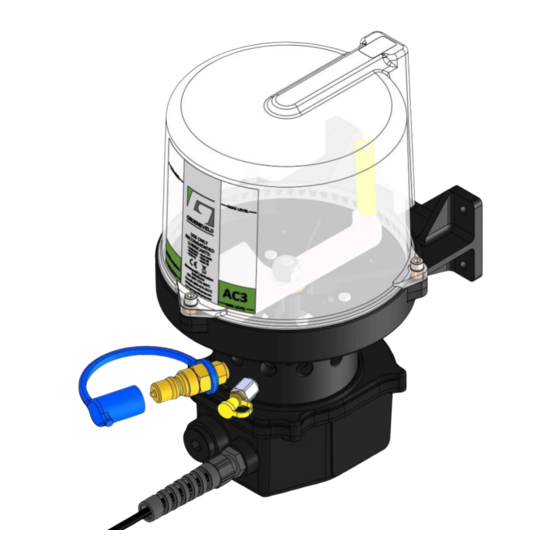
GROENEVELD—NORTH AMERICA
AC3 Installa on Manual
AC3 Pump Info
Maximum Working Pressure: 1740 psi (120 bar, 12 MPa)
Maximum opera ng temperature: 122°F/50°C
*(Note that opera ng over the maximum temperature will effect life of the pump)*
Minimum opera ng temperature: ‐40°F/‐40°C (with SAE 80/90 Oil), 5°F/‐15°C (with grade 2 grease).
IP Ra ng: IP66
Voltage: 12V or 24V
Power Ra ng: 2A
Fuse Ra ng: 2A
Max Line Length per Injector: 50 (15m)
This print and the ideas and principles represented on the print are the property of Groeneveld Lubrica on Solu ons. This print is not to be copied or reproduced (even extracts)
without prior wri en consent of Groeneveld. Every care has been taken to ensure the accuracy of the informa on contained in this publica on but no liability can be accepted for
any loss or damage whether direct, indirect or consequen al arising out of the use of the informa on contained herein.
AC3 Opera
on and Maintenance
GVNA_IM003.1_JF
Advertisement

Subscribe to Our Youtube Channel
Related Manuals for Groeneveld AC3


Summary of Contents for Groeneveld AC3
- Page 1 GROENEVELD—NORTH AMERICA AC3 Installa on Manual AC3 Pump Info Maximum Working Pressure: 1740 psi (120 bar, 12 MPa) Maximum opera ng temperature: 122°F/50°C *(Note that opera ng over the maximum temperature will effect life of the pump)* Minimum opera ng temperature: ‐40°F/‐40°C (with SAE 80/90 Oil), 5°F/‐15°C (with grade 2 grease). IP Ra ng: IP66 Voltage: 12V or 24V Power Ra ng: 2A Fuse Ra ng: 2A Max Line Length per Injector: 50 (15m) This print and the ideas and principles represented on the print are the property of Groeneveld Lubrica on Solu ons. This print is not to be copied or reproduced (even extracts) without prior wri en consent of Groeneveld. Every care has been taken to ensure the accuracy of the informa on contained in this publica on but no liability can be accepted for any loss or damage whether direct, indirect or consequen al arising out of the use of the informa on contained herein. AC3 Opera on and Maintenance GVNA_IM003.1_JF ...
- Page 2 Installa on Warnings WARNING INSTALLATION Only install the Groeneveld AC System if you are suitably qualified. Read the installa on instruc ons in full before commencing installa on. If in doubt contact Groeneveld on +1 (937) 276 4507 PERSONAL PROTECTIVE CLOTHING You must wear appropriate protec ve equipment when opera ng and servicing the equipment, this is to protect you from serious injury. This equipment includes but is not limited to: Protec ve eyewear. Respirators, protec ve clothing and gloves as recommended by the Lubricant manufacturer. PLASTIC PART CLEANING SOLVENT HAZARD Many solvents can damage plas c parts and cause them to fail, which could cause serious injury or property damage. Use only compa ble cleaning products. ...
- Page 3 UN ECE Reg.10.05 Automo ve Electromagne c Compa bility Direc ve 2011/65/EC Restric on of Certain Hazardous Substances Has been designed and manufactured to the following specifica ons: 97/23/EC, BS EN ISO 50498:2008 I hereby declare that the equipment named above has been designed to comply with the relevant sec ons of the above referenced specifica ons. The unit complies with all essen al requirements of the Direc ves. Signed: Name: Richard Butler Posi on: Divisional Managing Director Done at: Plymouth, UK Date: 04/01/2016 Document Ref: ISF 336 Issue 4 AC3 Opera on and Maintenance III ...
- Page 4 AC3 pump clearance: Moun ng Hole Dimensions AC3 standard moun ng posi ons: Select a suitable mounting point for the pump on the chassis, preferably in a position where it is protected from debris. Ensure adequate clearance for the looming, access to the override button and refilling clearance is made (see images on the following page).
-
Page 5: Pumping Units
Installa on Pumping Units Standard Pumping Units for AC3 Pumps. Output pressure Part No. ‘F’ No. Output/stoke Color Outlet Size Maximum Output pressure 1740 PSI / 120 Bar 78033‐PL F800091 0.010 cc Red from each Pumping Unit 78034‐PL F800092 0.015 cc Green 4mm OD 78035‐PL F800093 0.025 cc Yellow Ø 78036‐PL F800094 ... - Page 6 Installa on Wiring Informa on Installa on of the AC range of pumps should ideally incorporate direct connec ons to the vehicle igni on system. This provides automa c lubrica on whenever the igni on is switched on. A memory, built into the pumps printed circuit board, removes the possibility of over‐lubrica on on a short trip/ mul ‐drop opera on. Exis ng Vehicle electrical circuit(s) Chassis ground 2A Fuse Chassis ground AC3 Electrical Schema c 3 AC3 Opera on and Maintenance ...
- Page 7 9* 36 minutes delay The AC range of pumps are factory set to — con nuous opera on at 1.8rpm (se ng 0 on the PCB), unless otherwise specified. However, if the se ng needs to adjusted it can be easily changed Fig. 2 following the procedure below: To access the internal PCB and adjust the run se ngs, via the rotary switch. 1) Disconnect power to the pump. 2) Remove blanking plug from motor housing using an 8mm (or 5/16”) Hex Key (see Fig. 1 and 2). Make sure to retain O‐ring on the blanking blank. 3) Access PCB and adjust rotary switch as required using a 3/32” (2.4mm) flathead screwdriver (See Fig. 3 Fig. 3 and see 24V PCB (83344‐107) image below for rotary switch loca on). 24V PCB (83344‐107): 4) Re‐assemble, ensuring the O‐ring is correctly fi ed on the blanking plug. Torque to 5.0Nm (3.7lbf. ). 5) Reconnect power to the pump. Rotary switch set to posi on ‘0’. AC3 Opera on and Maintenance 4 ...
- Page 8 The following inspec on procedures are recommended to help ensure proper opera on of the AC chassis lubri‐ ca on system. Once the reservoir refill period has been determined make certain that the interval is part of scheduled maintenance. A. Inspect all lubrica on points for signs of FRESH grease, B. Check the condi on of all fi ngs and connec ons. Tighten or replace loose or damaged fi ngs. C. Check all lubrica on lines; make certain that there are not any breaks. Check for wear or chaffing that may lead to leakage. D. Confirm pump opera on by pressing Manual Override bu on (See Fig. 1B) and checking the indica on light flashes located on the bu on. If, during these checks, any issues are found use the Lubrica on Troubleshoo ng Chart on page 14 to help— resolve them. Fig. 1B Fig. 1A 5 AC3 Opera on and Maintenance ...
-
Page 9: Recommended Lubricants
2 Hard Minimum opera on ‐40°C / ‐40°F ‐35°C / ‐31°F ‐30°C / ‐22°F ‐25°C / ‐13°F ‐20°C / ‐4°F ‐15°C / 5°F Temp. Maximum +50°C / 122°F for all pumps* opera on *(Motor is operable up to 60°C/140°F, but opera ng at over 50°C/122°F shortens the life of the pump). Temp. Typical Refill Periods The AC3 refill periods range greatly, depending on the number of pumping units, the output quan es, and the programmed delay mes. Due to the accuracy of the pumping units output quan es and the reliability of pump func onality refill periods can be simply calculated to ensure that the pump and the bearing points don’t run dry. Use the following to calculate refill periods: Calcula on: Add up the total output from all pumping units: Key: (NxO ) + (NxO ) + (NxO ) + (NxO ) + (NxO ) + (NxO... - Page 10 Opera on AC3 System Output (cc’s/grams per hour) Timer Se ng (Delay Cycle) Injector 1.8rpm 0.9rpm 3min 7min 11min 15min 19min 24min 30min 36min 0.53 0.3 0.15 0.07 0.05 0.04 0.03 0.024 0.019 0.016 Green 0.8 0.44 0.22 0.11 0.07 ...
-
Page 11: Maintenance
Maintenance Pump Service Procedures A) AC3 Reservoir Replacement 1. Using 4mm (5/32”) hex key remove three screws holding the reservoir in posi on (see image 1). 2. Remove reservoir and ‘O’ ring (see image 2 and 3). 3. Posi on new ‘O’ ring on new reservoir. 4. Reassemble reservoir to pump body, ensuring the breather is closest to the moun ng bracket. 5. Reinsert and ghten screws to torque 3Nm (2.2lbf. ). Do not over ghten screws. In 3 places B) AC3 Paddle Replacement. 1. Follow step ‘1’ in sec on ’A’ to remove reservoir (see image 1 and 2). ... - Page 12 6. Place retaining plates in posi on and ghten the screws to torque 1.5Nm (1.1lbf. ). 7. Reconnect the Molex connector from the new motor to the PCB. 8. Locate new ‘O’ ring seal on motor cover. 9. Fit motor housing to motor cover and fix with the four original screws to torque 0.3Nm (0.22lbf. ). Loosen only F) AC Replacement of PCB: 1. Refer to steps ‘1’ and ‘2’ in sec on ’E’ to access PCB, but retain O‐ring. 2. Loosen and disconnect the RED and BLUE power cables from the PCB (see — image 16). Loosen and disconnect manual override cables, taking note of their connec on posi ons. Disconnect the motors Molex connector from PCB. 3. Remove and dispose of exis ng PCB, insert new one. Set the rotary switch on the new PCB to the same se ng as the old PCB (see image 17, right)*. 4. Reconnect wires from override bu on and power cable. Reconnect Molex ‐ connector as in step ‘7’ in sec on ‘E’. See page 5 for electrical schema c. 5. See step ‘9’ in sec on ’E’ for re‐assembly of motor housing, ensure correct fitment of O‐ring. AC3 Opera on and Maintenance 9 ...
- Page 13 Spare Parts AC3xxx SPARES 1a 10 AC3 Opera on and Maintenance ...
-
Page 14: Spare Parts
48 PORT CAMSHAFT ASSEMBLY AC3/SP5-5 F801181 60 PORT CAMSHAFT ASSEMBLY 83416-317 F801183 ZERK GREASE NIPPLE ASSEMBLY 83416-607 F801184 QUICK FILL ADAPTOR AND DUST CAP FOR AC3 21885-810 F801185 SELF LOCKING NUT (M10) 21171-806 F801186 FLAT WASHER (M10) 38580-126 F801187 AC3 MOUNTING BRACKET... - Page 15 Ordering Method AC3 Part Number Iden fica on AC 3 1 X X - X Reservoir Fill Type 3 Liter Standard/Zerk Voltage Manifold Size Quick/Bulk Fill Timer Se ng 12 Ports 12 VDC Con nuous 24 Ports 24 VDC 0.9 RPM 36 Ports *All bare pump orders are pre‐set to #1—0.9 RPM Con nuous. Refer to 48 Ports page 4 for mer se ng adjustment. ...
- Page 16 Ø4mm OD Primed w/ EP‐0 Grade Grease (15m/50 ) 152823‐164 F801103 Ø4mm OD Primed w/ EP‐0 Grade Grease (50m/164 ) 152057‐50 F801100 Ø4mm OD Un‐Primed (15m/50 ) 152057‐164 F801101 Ø4mm OD Un‐Primed (50m/164 ) Numbered Sleeves Part No. ‘F’ No. Descrip on 39257‐A1 F800109 For up to 12 point system 39257‐A2 F800110 For up to 24 point system 39257‐A3 F800111 For up to 36 point system 39257‐A4 F800112 For up to 48 point system 39257‐A5 F800113 For up to 60 point system AC3 Opera on and Maintenance 13 ...
- Page 17 6. All lubrica on points are Incorrect se ng of “Delay Time”. Increase “Delay Time” se ng. over lubricated. 7. Some lubrica on points Re‐configure pumping unit for lower out‐ Incorrect pumping unit output. put quan ty. are over-lubricated. Excessive pressure in the system caused by Check the system. Check suitability of — blockage. lubricant for applica on low temperature. 8. Split / burst lubrica on line One or more lubrica on points are blocked and Remove pipe from fi ng and flush bearing will not accept grease. through with grease gun. AC3 Opera on and Maintenance 14 ...
- Page 18 Work. pump and inside the pump. e) Manual Override bu on LED flashes, but motor e) Check for correct grounding (if applicable). does not run. Check wire connec ons. Defec ve PLC. Replace Controller Assembly. Defec ve Motor. Replace Motor. High pressure in the system Check the system / bearing points B.) Reduced Pump Low ambient temperature Not a defect(1 or 2 manual override — Speed. lubrica on cycles may be required) Bad wiring. Check all wires and connec ons to the switch. C.) Override Switch Pump does not work. Refer to “Problem A.” Does Not work. AC3 Opera on and Maintenance 15 ...
- Page 19 34 17 35 18 36 Pump Informa on: (for customer comple on) Part number:_________________________________________________________ Date code:___________________________________________________________ Supplier Name: _______________________________________________________ Supplier Address:______________________________________________________ Phone:______________________________________________________________ Contact:_____________________________________________________________ 16 AC3 Opera on and Maintenance ...
- Page 20 Follow Groeneveld on LinkedIn, Facebook and Twi er. Visit our web site for full Product Informa on, downloadable content and videos. GROENEVELD USA, INC. 4700 Lyons Rd. Dayton, OH 45342 937-276-4507 GROENEVELD LUBRICATION SOLUTIONS, INC. 8450 Lawson Rd., Unit #5 Milton, ON L9T 0J8 905-875-1017 www.groeneveld-group.com The Timken team applies their know‐how to improve the reliability and performance of machinery in diverse markets worldwide. The company designs, makes and markets high‐performance mechanical components, including bearings, gears, chain and related mechanical power transmission products and services. ISO 14001: 2015 ISO 9001:2015 ...
Need help?
Do you have a question about the AC3 and is the answer not in the manual?
Questions and answers
AC3/SP2-12VDC , would you have this in stock ?
The context does not explicitly state whether the Groeneveld AC3/SP2-12VDC is in stock. However, it provides a price and an option to add the item to the cart, which may indicate availability.
This answer is automatically generated