
Subscribe to Our Youtube Channel
Related Manuals for Groeneveld SingleLine F212164R00


Summary of Contents for Groeneveld SingleLine F212164R00
- Page 1 General Manual Automatic Greasing System SingleLine F212164R00 Your efficiency is our Challenge!
- Page 2 Groeneveld. This applies also to the drawings and diagrams appended. Groeneveld reserves the right to change parts at any time, without prior or direct notice to the customer. The contents of this manual may also be changed without prior notice.
-
Page 3: Table Of Contents
Automatic Greasing System SingleLine Table of Contents Preface - - - - - - - - - - - - - - - - - - - - - - - - - - - - - - - - - - - - - - - - - - - - - - - - - - - - - - - 5 General information - - - - - - - - - - - - - - - - - - - - - - - - - - - - - - - - - - - - - - - - - - - - - 6 1.1. - Page 4 Automatic Greasing System SingleLine Other components - - - - - - - - - - - - - - - - - - - - - - - - - - - - - - - - - - - - - - - - - - - - - 31 7.1.
-
Page 5: Preface
Automatic Greasing System SingleLine Preface This general manual gives a description of the SingleLine Automatic Greasing System. It aims at giv- ing insight in the system’s operation and possibilities. Furthermore, in this manual you will find the technical data on several components of the automatic greasing system. In this manual the following icons are used to inform or warn the user: ATTENTION Draws the user's attention to important information meant to avoid problems. -
Page 6: General Information
General information Introduction With an automatic greasing system of Groeneveld all grease points of a vehicle or machine are greased automatically at the correct moment and with the correct amount of grease. Because greasing takes places while the vehicle or machine is in operation, the applied grease is spread optimally over the whole surface to be greased. -
Page 7: Systems
Automatic Greasing System SingleLine Systems Pneumatic piston pump with SLT 1. Pump 4. Battery 7. Pressure switch 2. SLT 5. Metering unit 8. Solenoid valve 3. Ignition switch 6. Distribution block 9. Compressor Figure 2.1 Pneumatic piston pump with SLT At a time, set at the SLT, the circuit to the solenoid valve is closed. -
Page 8: System With Pneumatic Piston Pump And Impulse Counter
Automatic Greasing System SingleLine System with pneumatic piston pump and impulse counter As a rule, trailers and semi-trailers are equipped with a pneumatic brake impulse counter and not with an SLT. This is because of a lack of a continuous electrical supply. The standard version of the brake impulse counter is pneumatically operated and uses the air signal from the service line which is usually connected to the number 4 position of the trailer relay valve. -
Page 9: System With Electric Impulse Counter
Automatic Greasing System SingleLine 2.2.2 System with electric impulse counter 1. Pump 5. Distribution block 2. Brake impulse counter 6. Flow limiter 3. Signal impulse 7. Compressor 4. Metering unit Figure 2.3 System with electric impulse counter This corresponds broadly with that of a pneumatically operated brake impulse counter. The signal impulse is derived from the brake-light switch. -
Page 10: System With Electric Gear Pump
Automatic Greasing System SingleLine System with electric gear pump 1. Pump 4. Battery 2. SLT 5. Metering unit 3. Ignition switch 6. Distribution block Figure 2.4 System with electric gear pump The SLT starts the gear pump. The grease in the reservoir is pumped through the primary line, to the distribution blocks. -
Page 11: System With Electric Axial Plunger Pump
Automatic Greasing System SingleLine System with electric axial plunger pump 1. Pump 5. Primary line 2. SLT 6. Secundary line 3. Ignition switch 7. Metering unit 4. Battery 8. Distribution block Figure 2.5 System with electric axial plunger pump The SLT starts the plunjer pump. The grease in the reservoir is pumped through the primary line, to the distribution blocks. -
Page 12: Pumps
Automatic Greasing System SingleLine Pumps Pneumatic piston pump 3.1.1 Pump unit reservoir with follower plate 10. compressed air connection air venting channel 11. main air piston grease channel 12. spring return channel to reservoir 13. filler connector primary line connection 14. -
Page 13: Principle Of Operation
Automatic Greasing System SingleLine 3.1.2 Principle of operation If pressure is applied via the compressed air connection (10) the main piston (11) will be forced upwards applying pressure to the grease in chamber (15). The pressure in chamber (15) forces valve (16) against the seat. -
Page 14: Technical Data
Automatic Greasing System SingleLine 3.1.3 Technical data Grease pumps: part number F116479 F103544 F103336 F114016 reservoir capacity 4 liters 8 liters 4 liters 8 liters delivery 42 cc / stroke 60 cc / stroke ratio grease pressure 72 bar (for an air pressure of 8 bar) maximum grease pressure 100 bar temperature range... -
Page 15: The Electric Gear Pump
Automatic Greasing System SingleLine The electric gear pump 3.2.1 Pump unit follower plate pressure switch connection low level switch electric motor pressure control valve filler connector connector fitting 10. gear pump vent opening 11. reservoir primary line connector Figure 3.2 Electric gear pump F212164R00 Pumps 15... -
Page 16: Principle Of Operation
(NLGI 0 grease) at 20°C grease pressure 55 bar 55 bar temperature range -20°C to +70°C -20°C to +70°C (NLGI 0 grease) (NLGI 0 grease) at extreme circumstances please consult your local GROENEVELD-organization weight 6.7 kg 6.7 kg Pumps F212164R00... -
Page 17: The Electric Axial Plunger Pump
Automatic Greasing System SingleLine The electric axial plunger pump 3.3.1 Pump unit follower plate pressure switch reservoir electric motor guide rod of follower plate 10. return valve low level switch 11. filler port plunger pump 12. overflow port coupling for primary grease line 13. -
Page 18: Principle Of Operation
Automatic Greasing System SingleLine 3.3.2 Principle of operation The plunger pump (5) consists of six fixed plungers amid a ring duct. The six plungers are driven by the electric motor (9) through a mechanical transmission. In the channel between the ring duct and the outlet (6) of the pump unit, a pressure control valve (14) and an electrically operated return valve (10) have been built-in. -
Page 19: Technical Data
8 liters delivery 50 cc/minute at 20°C 50 cc/minute at 20°C oil pressure 55 bar 55 bar temperature range -20°C to +70°C -20°C to +70°C at extreme circumstances please consult your local Groeneveld-organization weight 9.2 kg 10.2 kg F212164R00 Pumps 19... -
Page 20: Singleline Timer
Automatic Greasing System SingleLine SingleLine Timer The SingleLine Timer (SLT) is a multifunctional Groeneveld product and is composed with high- grade components to guarantee the control of the Groeneveld SingleLine greasing system. 1. Pump cycle rotary switch 2. Connection for diagnosis 3. -
Page 21: Adjusting The Greasing Interval Pulses
Automatic Greasing System SingleLine Adjusting the greasing interval pulses The greasing interval pulses can be adjusted with the rotary switch (Figure 4.1/3) at the SLT. Rotate the switch by using a suitable screwdriver to the desirable position. As a confirmation, a short audible beep sounds when rotating the switch in each position. -
Page 22: Test Button Functions
Automatic Greasing System SingleLine Turn the rotary switch of the pump time (Figure 4.1/1) to the correct position after determining the pumping time between the manually started greasing cycle and the on- pressure signal. The correct position: round the determined pumping time to the next full minute and add one minute (see example). -
Page 23: Alarm Signals
Automatic Greasing System SingleLine Disabling the buzzer ATTENTION In this case installing a alarm signal lamp is necessary! Ensure that the SLT is not powered. Push the red test button. Switch ignition/power on. Release the red test button. A short pulsing audible beep indicates the buzzer is disabled. Enabling the buzzer Ensure that the SLT is not powered. -
Page 24: Technical Data
Automatic Greasing System SingleLine Technical data part number F125639 Supply voltage 12...24Vdc Pump output Maximum current pump output 15 A Alarm lamp output Maximum current alarm lamp output Impulse lamp output Maximum current impulse lamp output Pressure switch input Low level switch input Pulse input Test button Built-in alarm beeper... -
Page 25: Wiring Diagram
Automatic Greasing System SingleLine Wiring diagram Figure 4.2 Wiring diagram of SLT F212164R00 SingleLine Timer 25... -
Page 26: Impulse Counter
Automatic Greasing System SingleLine Impulse counter As a rule trailers and semi-trailers do not have a continuous electrical supply. For this reason an SLT cannot be used. In its place a brake impulse counter will be used. This may be electrically or pneumatically operated. -
Page 27: Setting The Number Of Brake Applications
Automatic Greasing System SingleLine activation is through pulses from the pneumatic system before the relay valve (or trailer reaction valve). The compressed air operates a piston, which in turn rotates the operating cam. After the preset number of pulses the operating cam opens the air valve through which compressed air passes to the pump. -
Page 28: Metering Units
Automatic Greasing System SingleLine Metering units Figure 6.1 Distribution block with metering units There are 11 metering unit types (1) available for the SingleLine system, each with a differing metered grease quantity. By careful selection of the type of metering unit each grease point can be provided with the right quantity of grease. -
Page 29: Operating Principle
Automatic Greasing System SingleLine Operating principle 6.2.1 Point of departure Figure 6.3 Metering unit in initial position Figure 6.3 illustrates a new metering unit. One that has not yet been filled with grease. Item (1) is the spacer, which determines the delivery of the metering unit (see paragraph 6.1). The metering units that are used in your greasing system may differ externally, or even internally, from the one illustrated here. -
Page 30: Phase B
Automatic Greasing System SingleLine 6.2.3 Phase B Figure 6.5 Metering unit in phase B When the pump stops and as the grease pressure in the primary line drops, spring (7) will push plunger (4) back to the left, closing off channel (1). O-ring (9) prevents grease from being sucked back from chamber (6). -
Page 31: Other Components 31
Automatic Greasing System SingleLine Other components Solenoid valve Figure 7.1 Solenoid valve The solenoid valve (Figure 7.1) between the air tank and the pneumatic pump (usually fitted to the pump) is a normally closed, free venting type. The valve is connected electrically by an M24 screw connector. -
Page 32: Pressure Switch
Automatic Greasing System SingleLine Pressure switch Figure 7.2 Pressure switch A pressure switch is included in the greasing system (in the primary line) to provide an alarm for too low a pressure in the system during the greasing cycle. This switch closes at a pressure of 40 bar, making a connection to earth. If this does not happen during the greasing cycle, because insufficient or no grease pressure is generated, an alarm will be given. -
Page 33: Reservoir
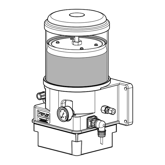
Automatic Greasing System SingleLine Reservoir Figure 7.3 Pneumatic pump The reservoir (2) is made from impact-resistant plastic that can withstand the influences of fluctuating temperatures. The reservoir can hold a quantity of grease that in most cases is sufficient for about 4 months, depending on the number of grease points. The minimum level (5 cm) is marked by a label (3) on the reservoir. -
Page 34: Refilling The Reservoir
NLGI 0-grease of EP quality and moreover must not contain graphite. Groeneveld has developed an EP grease in the NLGI class 0 especially for use in automatic greasing systems. This grease - Greenlube EP-0 - combines the best qualities of various types of greases. The use of Greenlube grease is recommended for the greasing system. -
Page 35: Maintenance
Automatic Greasing System SingleLine Maintenance General The maintenance of Groeneveld’s SingleLine greasing systems can be combined with the normal maintenance of the vehicle or machine. WARNING When cleaning the vehicle or machine with a high-pressure water/steam jet cleaner, the pump of the greasing system should not be directly exposed to the jet. -
Page 36: Fault Diagnosis
Automatic Greasing System SingleLine Fault diagnosis 10.1 General malfunction reports Fault Cause Action 1. All points to be greased a. Pump reservoir is empty. a. Fill the reservoir. See chapter 8. are dry. b. Reservoir filled with grease b. Remove and clean the reservoir. Refit that is too thick and and fill the reservoir with the correct unsuitable for the system. -
Page 37: Malfunction Report Of The Slt
ATTENTION! Optional, the SLT has to be set to always on after alarm signal via the Groeneveld PC-GINA program. Low level measured in reservoir. 1 short audible beep and/or Alarm signal lamp continuously alarm lamp signal 30 seconds pulsing. - Page 38 Automatic Greasing System SingleLine Notes Fault diagnosis F212164R00...
- Page 40 Groeneveld Transport Efficiency B.V., Stephensonweg 12, 4207 HB Gorinchem, P.O. Box 777, 4200 AT Gorinchem, The Netherlands, Ph : +31 183 641 400, F : +31 183 624 474, http://www.groeneveld-group.com...
Need help?
Do you have a question about the SingleLine F212164R00 and is the answer not in the manual?
Questions and answers