Table of Contents
Advertisement
Advertisement
Table of Contents

Related Manuals for Zimmer Biomet Vanguard ID Total Knee


Summary of Contents for Zimmer Biomet Vanguard ID Total Knee
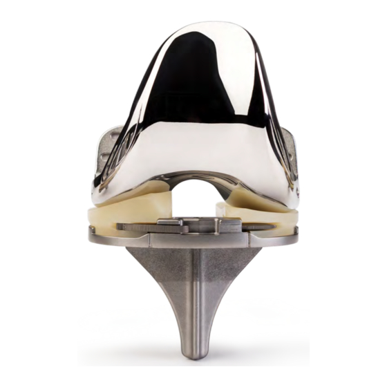
- Page 1 Vanguard ID Total Knee ® Surgical Technique...
-
Page 3: Table Of Contents
Table of Contents Overview ........................2 Preoperative Planning ....................4 Incision ........................4 Patella Preparation ....................5 Patella Resection Femoral Preparation ....................8 Distal Femoral Resection Femoral Sizing 4-in-1 Femoral Cuts Tibial Preparation ....................14 Tibial Resection Stem Preparation Sizing Chart ......................22 Trial Reduction ...................... -
Page 4: Overview
Vanguard ® ID Total Knee Surgical Technique Overview The Vanguard ID Surgical Technique consists of: • Vanguard XP Femoral Component ® • One tibial tray: XP-CR Interlok Tibial Tray ® • Two bearing designs: XP-XP and XP-AS The components can be used in different combinations, depending on the patient’s soft tissue status (see table below). - Page 5 Vanguard ID Total Knee Surgical Technique ® Description Zimmer Biomet manufactures a variety of knee joint replacement prostheses intended for application with or without bone cement. Knee joint replacement components include: femoral, tibial, and patellar components. Components are available in a variety of designs and size ranges intended for both primary and revision applications.
-
Page 6: Preoperative Planning
Vanguard ® ID Total Knee Surgical Technique Valgus Angle Mechanical Axis Anatomic Perpendicular Resection Figure 1 Figure 2 Preoperative Planning Incision Assess bone stock and potential ligament instability The Vanguard ID Knee utilizes the Vanguard XP Total and the anatomical axis with 36 inch long standing Knee Instrumentation, which is also designed for A/P X-rays. -
Page 7: Patella Preparation
Vanguard ID Total Knee Surgical Technique ® Patella Preparation Figure 3 Figure 4 Patella Resection Use the patella clamp surface cut guide to perform the Vanguard ID Tip: Preparation of the patella at initial, flat patellar resection. this time frees up the joint capsule and facilitates exposure for the remainder of the case. - Page 8 Vanguard ® ID Total Knee Surgical Technique Figure 5 Figure 6 Patella Resection (cont.) Option 1: Surface Clamp (cont.) Option 2: Patella Milling 1-peg patellar component: Tilt the patella for patella preparation. – Use the 1-peg patellar drill guide to locate the Remove the osteophytes and peripatellar tissues down placement of the central peg.
- Page 9 Vanguard ID Total Knee Surgical Technique ® Figure 7 Patella Resection (cont.) Option 2: Patella Milling (cont.) Note: The magnetic spacer bit includes the depth Note: The patella size and thickness will determine of the peg. Do not sink the drill bit prior to setting if a standard or thin patella should be used.
-
Page 10: Femoral Preparation
Vanguard ® ID Total Knee Surgical Technique Femoral Preparation 1 mm 11 mm Figure 8 Figure 9 Option 1: Adjustable Distal Distal Femoral Resection Femoral Resection Guide Utilize the .375 inch intramedullary (IM) drill to Set the adjustable distal cut guide to the desired valgus penetrate the intercondylar notch of the distal femur angle by pressing and turning the valgus angle dial to a depth of approximately 1.5–2 inch (3.5–5 cm) - Page 11 Vanguard ID Total Knee Surgical Technique ® Figure 10 Figure 11 Distal Femoral Resection (cont.) Option 1: Adjustable Distal Femoral Resection Guide (cont.) Assemble the IM rod and adjustable distal cut guide Continue sliding the adjustable distal adaptor until the by inserting the IM rod through the central hole of the block is sitting against the anterior cortex.
- Page 12 10 | Vanguard ® ID Total Knee Surgical Technique 9 mm Figure 12 Figure 13 Distal Femoral Resection (cont.) Option 2: Fixed Distal Femoral Resection Guide (cont.) Choose the appropriate left or right valgus wing and Note: To confirm the valgus angle, the alignment assemble it onto the IM rod by sliding it through the handle can be inserted into the adjustable distal central hole.
-
Page 13: Femoral Sizing
Vanguard ID Total Knee Surgical Technique 11 | ® ^ 00 Fixed Figure 14 Figure 15 Femoral Sizing Assemble the selected right or left A/P sizer feet to Feet options include: the A/P sizer body. – Adjustable A/P sizer dial feet, left and right with the ability to set external rotation from 0 to 10 degrees (Figure 14). - Page 14 12 | Vanguard ® ID Total Knee Surgical Technique Figure 16 Femoral Sizing (cont.) Note: Assessing the A/P femoral axis, the Vanguard ID Tip: If the size indicated is in- epicondylar axis, flexion gap and the tibial shaft between sizes, use the smaller of the two sizes, axis can further optimize femoral rotation.
-
Page 15: 4-In-1 Femoral Cuts
Vanguard ID Total Knee Surgical Technique 13 | ® Figure 17 4-in-1 Femoral Cuts Choose the Vanguard XP Femoral 4-in-1 Block that Once the block position is satisfactory, resect the matches the selected size (Figure 17). anterior and posterior bone and the anterior and posterior chamfers with a 1.37 mm thick saw blade in Place the block into the 1/8 inch distal femur holes. -
Page 16: Tibial Preparation
14 | Vanguard ® ID Total Knee Surgical Technique Tibial Preparation Figure 18 Figure 19 Tibial Resection Resection Posterior slope is adjusted by depressing the button Attach the tibial universal cutting block (which has a 7 on the side of the EM tibial guide base and moving the degrees posterior slope built-in) to the EM tibial guide. - Page 17 Vanguard ID Total Knee Surgical Technique 15 | ® Figure 20 Figure 21 Tibial Resection (cont.) Resection (cont.) Secure the EM tibial guide body to the tibia with one Attach the tibial stylus to the universal tibial cutting pin (headed threaded), placed in either the medial or block by placing the appropriate stylus tongue into the lateral hole in the EM tibial guide yoke (not through slot on the universal tibial cutting block (Figure 20):...
- Page 18 16 | Vanguard ® ID Total Knee Surgical Technique Fine-tune Adjustment Figure 22 Figure 23 Tibial Resection (cont.) Fine Tuning Tibial Resection Height Repeat previous step at 90 degrees of flexion to ensure Bring the knee into extension and place the tibial that flexion and extension spaces match.
- Page 19 Vanguard ID Total Knee Surgical Technique 17 | ® Headed/ Threaded Pin Standard Figure 24 Figure 25 Tibial Resection (cont.) Fine Tuning Tibial Resection Height (cont.) To create a captured cut slot, secure the tibial cutting Remove the tibial resection spacer. block insert onto the universal tibial cutting block After the horizontal resection level is set, place one 1/8 (Figure 25).
- Page 20 18 | Vanguard ® ID Total Knee Surgical Technique Figure 26 Figure 27 Tibial Resection (cont.) Fine Tuning Tibial Resection Height (cont.) The cut block may be used as a surface block by not Using the flat rasp, fine-tune the resected tibia to ensure attaching the tibial cutting block insert (Figure 26).
- Page 21 Vanguard ID Total Knee Surgical Technique 19 | ® Figure 28 Figure 29 Tibial Resection (cont.) Flexion/Extension Gap Check Tibial Sizing Check the flexion and extension gaps with the tibial Place the knee in maximum flexion with a Z-retractor spacer to ensure that there is adequate spacing (9 mm medially and laterally to provide maximum exposure.
- Page 22 20 | Vanguard ® ID Total Knee Surgical Technique Figure 30 Tibial Resection (cont.) Trialing Based on the tibial template size, select the appropriate Vanguard ID Tip : When trialing range of motion, tibial trial and the appropriate medial and lateral if the medial and lateral bearings rise up in flexion: bearing based on the constraint level desired (see bearing compatibility chart, page 24).
- Page 23 Vanguard ID Total Knee Surgical Technique 21 | ® Figure 31 Tibial Preparation Place the knee in maximum flexion and sublux the tibia Perform an extramedullary alignment check by anteriorly using a PCL retractor and place a Z-retractor placing the 1/4 inch alignment rod through the tibial medially and laterally.
-
Page 24: Stem Preparation
22 | Vanguard ® ID Total Knee Surgical Technique Figure 32 Figure 33 Stem Preparation Trialing Carefully impact the cruciate punch through the tibial The following bearing combinations are options based punch mask until fully seated (Figure 32). on implant size (see the below sizing chart). Assemble the appropriate tibial tray trial cruciate stem Note: Medial and lateral bearings may differ in insert to the primary tibial tray trial (Figure 33 A and B). - Page 25 Vanguard ID Total Knee Surgical Technique 23 | ® Final Trial Reduction Figure 34 Figure 35 Femur With all bone surfaces and soft tissues prepared, Vanguard ID Tip: The Vanguard XP Bearings are complete a trial reduction. not symmetric. They have unique medial and Place the femoral trial onto the femur with dedicated lateral articulations.
- Page 26 24 | Vanguard ® ID Total Knee Surgical Technique Bearing Compatibility Chart Vanguard XP Femoral/XP-AS Bearing Compatibility XP Femorals 52.5 57.5 62.5 67.5 72.5 77.5 XP-AS Bearings 79, 83, 87,91 Vanguard XP-CR (ID) Tibial Tray / XP-XP Bearing Compatibility XP-CR (ID) Tibial Trays XP-XP Bearings Vanguard XP-CR (ID) Tibial Tray / XP-AS Bearing Compatibility XP-CR (ID) Tibial Trays...
- Page 27 Vanguard ID Total Knee Surgical Technique 25 | ® Vanguard ID Combinations Intact, Functioning PCL: Right Knee Levels of Articulation Medial Side Lateral Side Standard CR: Medium constraint medially XP-XP Right Medial Bearing XP-XP Right Lateral Bearing Low constraint laterally Standard CR: Medium constraint medially XP-XP Right Medial Bearing...
- Page 28 26 | Vanguard ® ID Total Knee Surgical Technique Vanguard ID Constructs Cruciate Retaining Anterior Stabilized Medial Stabilized Lateral Stabilized...
-
Page 29: Implant Reduction
Vanguard ID Total Knee Surgical Technique 27 | ® Implant Reduction Figure 36 Tibial Tray Implantation As soon as the cement properties permit, apply a thin If a tourniquet above the knee is not already in use, layer over the entire underside of the tibial component. place and/or inflate throughout preparation of bone for cementation, as well as mixing, application and Avoid contamination of the implant-cement interface. - Page 30 28 | Vanguard ® ID Total Knee Surgical Technique Figure 37 Tibial Tray Implantation (cont.) After pressurization, all cement that remains proud Remove any excess cement from the posterior aspect of the bone should be removed. A 1/2 inch (12.7 mm) of the tibia using an angled elevator (Woodson).
-
Page 31: Femoral Component Implantation
Vanguard ID Total Knee Surgical Technique 29 | ® Figure 38 Femoral Component Implantation While mixing another 40g unit of cement, pulse lavage Any cement remaining proud on the posterior facet and dry the femoral side again. should be scraped flush to the bone before proceeding, so that it is not displaced and inaccessible upon seating As soon as the cement properties permit, apply a layer of the femoral component:... - Page 32 30 | Vanguard ® ID Total Knee Surgical Technique Figure 39 Femoral Component Implantation (cont.) Place the femoral component onto the end of the femoral Reduce the patella and insert the medial tibial trial impactor and insert it manually as far as possible. bearing.
-
Page 33: Patellar Component Implantation
Vanguard ID Total Knee Surgical Technique 31 | ® Figure 40 Figure 41 Tibial Bearings and Patellar Component Implantation Locking Bar Implantations Pulse lavage and dry patella. Remove the tibial bearings and select the appropriate tibial bearings and insert onto the tibial tray (Figure 41). With the knee in full extension, apply a 2 to 3 mm thick layer of cement onto the appropriate patellar Push posteriorly as far as possible using finger pressure. - Page 34 32 | Vanguard ® ID Total Knee Surgical Technique Figure 42 Figure 43 Tibial Bearings and Locking Bar Implantations (cont.) Use the bearing pre-setting tool (Figure 42) to set Place the large curved end of the locking bar inserter each bearing into position before using the locking (etched “bar”) in the notch on the locking bar.
- Page 36 Dr. Thomas Aleto All content herein is protected by copyright, trademarks and other intellectual property rights owned by or licensed to Zimmer Biomet or its affiliates unless otherwise indicated, and must not be redistributed, duplicated or disclosed, in whole or in part, without the express written consent of Zimmer Biomet.
Need help?
Do you have a question about the Vanguard ID Total Knee and is the answer not in the manual?
Questions and answers