Table of Contents
Advertisement
Quick Links
Advertisement
Table of Contents

Related Manuals for Zimmer Biomet Sesamoid Plasty V2


Summary of Contents for Zimmer Biomet Sesamoid Plasty V2
- Page 1 Sesamoid Plasty V2 ® User Guide...
-
Page 3: Table Of Contents
Table of Contents Symbols and Icons ....................2 Introduction ......................3 System Overview ...................... 4 Sesamoid Plasty Computer ..................5 Sesamoid Plasty Camera ..................7 Laser Positioning System ..................8 Cleaning and Disinfection ..................9 Transportation and Storage ................... 10 Packaging the Sesamoid Plasty ................ -
Page 4: Symbols And Icons
Sesamoid Plasty User Guide ® Symbols and Icons The following symbols and icons can be found on the Sesamoid Plasty or on the labeling of components. Symbol Meaning Location General warning sign Computer Power Indicator Camera front panel Camera status indicator (tracking mode) Camera front panel Camera error indicator Camera front panel... -
Page 5: Introduction
Sesamoid Plasty User Guide ® Introduction The Sesamoid Plasty is Zimmer Biomet’s hardware Operating Principle of the Sesamoid Plasty platform for the unicondylar*, total knee and total The laser pointer is used to orient the camera toward hip replacement* applications. The platform and... -
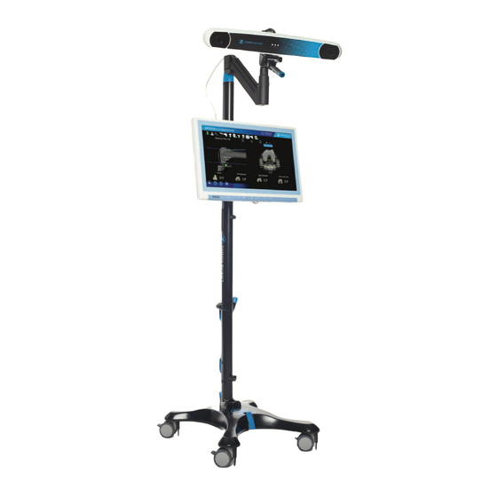
Page 6: System Overview
Ethernet cable CAUTION: It is recommended that if the Sesamoid Plasty is used with configuration other than that shipped by Zimmer Biomet, users should verify compliance with General Requirements for Basic Safety and Essential Performance for Medical Devices IEC 60601-1. -
Page 7: Sesamoid Plasty Computer
Sesamoid Plasty. Connections CAUTION: Do not position the Sesamoid Plasty • Only use the HDMI cable provided by Zimmer Biomet in a way that makes unplugging the power cord to connect the Sesamoid Plasty to an external display. - Page 8 Sesamoid Plasty User Guide ® Sesamoid Plasty Computer (cont.) CAUTION: Do not remove the cap on the camera connector, this port is reserved for future use and not to connect to a local network. CAUTION: The openings on the enclosure are for air convection to protect the equipment from overheating.
-
Page 9: Sesamoid Plasty Camera
Sesamoid Plasty User Guide ® Sesamoid Plasty Camera Overview of the Polaris Spectra Camera CAUTION: Depending on ambient temperature, it could take several minutes for the Sesamoid Plasty Camera to reach operating temperature from a cold-start at normal temperature (the power LED will flash when warming up and stay lit when ready). -
Page 10: Laser Positioning System
Sesamoid Plasty User Guide ® Laser Positioning System The laser pointer helps approximate the correct camera aim by projecting a low-power laser beam along the center of the camera’s field of view. Press the "On/Off" trigger button to activate the laser, and release the button to deactivate the laser. -
Page 11: Cleaning And Disinfection
Sesamoid Plasty User Guide ® Cleaning and Disinfection CAUTION: Always isolate the equipment from the main electrical supply prior to cleaning and disinfection in order to prevent electrical shocks. CAUTION: Immersing or soaking the Sesamoid Plasty Computer or the Sesamoid Plasty Camera into liquid could result in malfunction of the unit. -
Page 12: Transportation And Storage
Sesamoid Plasty User Guide 10 | ® Transportation and Storage Assembly of the Sesamoid Plasty Moving the Sesamoid Plasty while Assembled 1. Unfold the first pole section located close to the base of the Sesamoid Plasty Stand. Tighten The Sesamoid Plasty must be handled with care. the locking mechanism of that pole section You must avoid any type of impact to the Sesamoid and complete the same operation for each pole... - Page 13 Sesamoid Plasty User Guide 11 | ® Transportation and Storage (cont.) Disassembly of the Sesamoid Plasty The steps to fold down the Sesamoid Plasty (shown in Figure 9) are: a. Remove the Sesamoid Plasty Computer from the stand. b. Remove the Sesamoid Plasty Camera and the camera arm from the stand.
-
Page 14: Packaging The Sesamoid Plasty
Sesamoid Plasty User Guide 12 | ® Packaging the Sesamoid Plasty Transport Cases If the Sesamoid Plasty is to be frequently shipped, a series of reusable packaging material is available (Figure 10). A. The large box contains the Sesamoid Plasty Stand and the camera arm. -
Page 15: Preventive Inspection And Maintenance
Sesamoid Plasty User Guide 13 | ® Preventive Inspection and Maintenance CAUTION: All user maintenance must be done by appropriately trained personnel. Individual components of the Sesamoid Plasty Camera and Computer contain no user-serviceable parts. Maintenance by untrained personnel may present an electric shock hazard. -
Page 16: Technical Specifications
Sesamoid Plasty User Guide 14 | ® Technical Specifications Sesamoid Plasty Specifications The specifications listed apply to system operation under typical conditions. SESAMOID PLASTY FOOTPRINT 58.5 cm x 50.9 cm. Sesamoid Plasty Approvals ANSI/AAMI ES 60601-1 SESAMOID PLASTY HEIGHT CAN/CSA-C22.2 No. 60601-1 The maximum possible height of the system is 224.8 cm. - Page 17 Sesamoid Plasty User Guide 15 | ® Technical Specifications (cont.) Sesamoid Plasty Specifications (cont.) CAUTION: The Sesamoid Plasty has been tested and is in compliance with the electromagnetic MONITOR DIMENSIONS compatibility (EMC) requirements for emissions. In some situations, it is still possible that radiated 55 cm x 36 cm x 11.4 cm (irregular) electromagnetic fields such as those from portable MONITOR WEIGHT...
- Page 18 Sesamoid Plasty User Guide 16 | ® Technical Specifications (cont.) Product Regulatory Notices The Sesamoid Plasty is designed for use in the operating room, with the following exceptions: Wireless Communications • Near portable and mobile RF communication equipment that radiate electromagnetic fields as The Sesamoid Plasty Computer contains an RF those may cause performance degradation.
- Page 19 Sesamoid Plasty User Guide 17 | ® Technical Specifications (cont.) Product Regulatory Notices (cont.) FCC Notice This equipment has been tested and found to comply with the limits for a Class B digital device, pursuant to part 15 of the FCC Rules. These limits are designed to provide reasonable protection against harmful interference in a residential installation.
- Page 20 Sesamoid Plasty User Guide 18 | ® Technical Specifications (cont.) Guidance and Manufacturer’s Declaration Electromagnetic Emissions The Sesamoid Plasty Computer is intended for use in the electromagnetic environment specified below. The customer or the user of the Sesamoid Plasty Computer should assure that it is used in such an environment. Emissions test Compliance Electromagnetic environment –...
- Page 21 Sesamoid Plasty User Guide 19 | ® Technical Specifications (cont.) Guidance and Manufacturer’s Declaration (cont.) Electromagnetic Immunity The Sesamoid Plasty Computer is intended for use in the electromagnetic environment specified below. The customer or the user of the System Controller Computer should assure that it is used in such an environment. Immunity test IEC 60601 Test level Compliance level...
-
Page 22: Disposal Of Equipment
Disposal of Equipment In the European Union, components bearing the symbol (shown right) must be disposed of using local recycling initiatives, or returned to Zimmer Biomet for recycling. See Symbols section, page 2, for further information. The batteries directive 2006/66/EC includes requirements on the removability of batteries from waste equipment in EU Member States. -
Page 23: Troubleshooting Of The Sesamoid Plasty
Sesamoid Plasty User Guide 21 | ® Troubleshooting of the Sesamoid Plasty Camera Arm not Holding its Position Communication Errors In some occasions, the camera may not hold its When the Sesamoid Plasty Camera communication position while orienting it to the operating field. The error message is displayed following steps might fix this issue. - Page 24 All content herein is protected by copyright, trademarks and other intellectual property rights, as applicable, owned by or licensed to Zimmer Biomet or its affiliates unless otherwise indicated, and must not be redistributed, duplicated or disclosed, in whole or in part, without the express written consent of Zimmer Biomet.
Need help?
Do you have a question about the Sesamoid Plasty V2 and is the answer not in the manual?
Questions and answers