
Related Manuals for Zimmer Biomet Universal Clamp


Summary of Contents for Zimmer Biomet Universal Clamp
- Page 1 Thoracolumbar Solutions Universal Clamp ® Spinal Fixation System Surgical Technique Guide...
- Page 2 Universal Clamp—Surgical Technique Guide...
-
Page 3: Table Of Contents
Elevators Important Information on the Universal Clamp Spinal Fixation System Zimmer Biomet Spine does not practice medicine. This technique was developed in conjunction with health care professionals. This document is intended for surgeons and is not intended for laypersons. Each surgeon should exercise his or her own independent judgment in the diagnosis and treatment of an individual patient, and this information does not purport to replace the comprehensive training surgeons have received. -
Page 4: Implant Overview
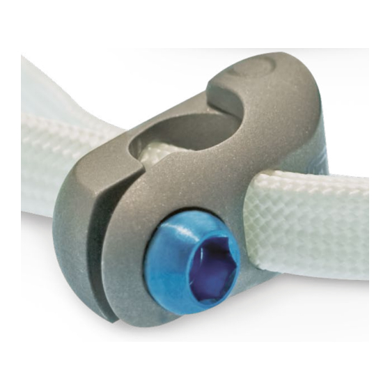
One woven polyester band 5.5mm Universal Clamp 6.0mm Universal Clamp • One locking screw 6.35mm (1/4") Universal Clamp Note: The Universal Clamp diameter must match that of the rod to ensure proper biomechanical fixation. Titanium DESCRIPTION 4.5mm Universal Clamp 4.75mm Universal Clamp 5.5mm Universal Clamp... -
Page 5: Implant Preassembly
Preassemble the Implant • The band is gently pulled through the slots until reaching the end of the band with two The Universal Clamp implant is partially assembled • metallic buckles. by passing the malleable leader of the band through... - Page 6 Universal Clamp—Surgical Technique Guide IMPLANT PREASSEMBLY (continued) STEP 2, OPTION 1A Caution: During band passage, maintain Standard Band Passage: Laminar Fixation upward pressure on the malleable leader to ensure • Prior to band passage, the ligamentum flavum and the the band stays in contact with the anterior aspect of inferior edge of the lamina may be partially resected to the lamina and does not push or bow into the dura.
- Page 7 • When the band is visible at the cephalad margin • of the lamina, hold and stabilize the tip of the Requires Universal Clamp Instrument Kit band with the bengolea forceps. SNA027-0008-PL. • To avoid pushing the band into the dura, maintain •...
- Page 8 Universal Clamp—Surgical Technique Guide IMPLANT PREASSEMBLY (continued) STEP 2, OPTION 2B STEP 2, OPTION 2C Band Passer Band Threading • To pass the band, insert the band passer into the • Use the band passer with the handle lateralized in eyelet near the tip of the band.
-
Page 9: Loop Preparation
Universal Clamp—Surgical Technique Guide LOOP PREPARATION STEP 2, OPTION 2D STEP 3 Band Pushing Loop Preparation • When the tip of the band becomes visible at • Once the band has been passed around the lamina, the caudal margin of the transverse process,... -
Page 10: Connection To The Rod
Note: Do not tighten the locking screw at Note: Verify that the rod diameter and rod material this time, as this may prevent reduction or match those of the Universal Clamp implant, and that the distraction/compression capability. arrow etched on the Universal Clamp implant is visible Warning: Do not tighten the locking screw with and pointing toward the mid-line of the spinal column. -
Page 11: Reduction
Universal Clamp—Surgical Technique Guide REDUCTION Side Button STEP 5A STEP 5B Modular Reduction Tool Assembly Modular Reduction Tool Disassembly • The band may be tightened using the reduction • The reduction tool can be disassembled by tool. The modular reduction tool is assembled... - Page 12 • Place the tip of the reduction tool over the • Wrap the working loop of the Universal Clamp’s Universal Clamp Implant and onto the rod. band around the capture post of the reduction tool; squeeze the reduction tool’s handle. This action lengthens the working loop and shortens the anatomic loop of the band.
- Page 13 3.5mm the capture post slides to the indicator line (see inset), final screwdriver to final tighten the Universal Clamp 700N of tension has been achieved. Tensioning prior implant. The reduction tool may then be removed to this indicator line is at the surgeon’s discretion and...
-
Page 14: Final Construct
IMPLANT REMOVAL STEP 8 Cutting the Band • To remove the Universal Clamp System, use the 3.5mm final screwdriver to loosen and remove the When all reduction barrels have been removed • locking screw and take the metal jaws off the rod. -
Page 15: Kit Contents
Universal Clamp—Surgical Technique Guide KIT CONTENTS Implants DESCRIPTION PART NUMBERS* Universal Clamp, Band SN2027-0-20000, SNA027-0-20000 Universal Clamp, Locking Screw, Titanium Alloy SN2027-0-20006S, SNA027-0-20006S Universal Clamp, 4.5mm, Titanium Alloy SN2027-0-20045 Universal Clamp, 4.75mm, Titanium Alloy SN2027-0-20047 Universal Clamp, 5.5mm, Titanium Alloy SN2027-0-20055, SNA027-0-20055 Universal Clamp, 5.5mm, Clamp, Titanium Alloy... -
Page 16: Supporting Instrumentation And Implants
Universal Clamp—Surgical Technique Guide SUPPORTING INSTRUMENTATION AND IMPLANTS Implant Positioner Tapered Screw Starter PART NUMBER PART NUMBER SN2027-1-02600 SN2027-1-02512 Final Screwdriver, 3.5mm Bengolea Forceps PART NUMBER PART NUMBER SN2027-1-02570 20cm SN2027-1-02270 26cm SN2027-1-02276 Reduction Tool PART NUMBER Reduction Tool Barrel... -
Page 17: Elevators
Universal Clamp—Surgical Technique Guide SUPPORTING INSTRUMENTATION AND IMPLANTS (continued) Elevators Note: Elevators and Band Passers are only used to facilitate passage around the transverse process. Elevators and Band Passers should not be used for sublaminar passage. Only included in Universal Clamp Instrument Kit SNA027-0008-PL. - Page 18 Note: Elevators and Band Passers are only used to facilitate passage around the transverse process. Elevators and Band Passers should not be used for sublaminar passage. Only included in Universal Clamp Instrument Kit SNA027-0008-PL. Draw the Universal Clamp System’s polyester band through the prepared pathway around the transverse process.
-
Page 19: Important Information On The Universal Clamp Spinal Fixation System
Severe fractures such that segments may not be Indications maintained in satisfactory proximate reduction. The Universal Clamp System is a temporary implant for use • Any entity or condition that compromises the possibility in orthopedic surgery. The system is intended to provide of fusion, such as cancer, kidney dialysis or osteopenia. - Page 20 The details the patients. General surgical risk should be explained to the of this insertion are found in the Universal Clamp System patients prior to surgery. Surgical Technique supplied by Zimmer Biomet Spine.
- Page 21 There is a potential for heating and migration in the 2. Disassembly, fraying, kinking, loosening, bending MR environment. or breakage of any or all of the Universal Clamp System implant components. • There is the potential for metal implants to create MR imaging artifacts in the vicinity of the implant.
- Page 22 Universal Clamp—Surgical Technique Guide NOTES...
- Page 24 Zimmer Biomet Spine, Inc. or its affiliates unless otherwise indicated, and must not be redistributed, duplicated or disclosed, in whole or in part, without the express written consent of Zimmer Biomet Spine. This material is intended for health care professionals, the Zimmer Biomet Spine sales force and authorized representatives.
Need help?
Do you have a question about the Universal Clamp and is the answer not in the manual?
Questions and answers