Table of Contents
Advertisement
Advertisement
Table of Contents

Related Manuals for Zimmer Biomet OSS Compress


Summary of Contents for Zimmer Biomet OSS Compress
- Page 1 Orthopedic Salvage System ™ Compress Device ® Surgical Technique...
-
Page 3: Table Of Contents
Table of Contents Quick Reference Guide ..................... 2 Device Description ....................3 Resection ........................4 No Face Adapter Provisional Construct ..............4 Canal Preparation ..................... 5 Anchor Plug....................... 9 Instrumentation Assembly ................... 9 Instrumentation Assembly Alignment ..............13 Anchor Plug Implantation ................. 15 Transverse Pins ....................... -
Page 4: Quick Reference Guide
Compress Device Surgical Technique Quick Reference Guide Compress Resection Chart Distal or Proximal Segment(s) Femoral Component Total Taper Adapter Spindle Collar Construct (cm) 5 cm 1 cm 3 cm 4 cm 9 cm 11 cm 13 cm 15 cm 17 cm Length Standard, RS or Reduced Resection... -
Page 5: Device Description
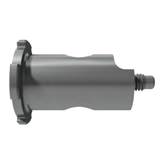
Compress Device Surgical Technique Immediate Postoperative 12 Years Postoperative Short Compress Spindle Standard Compress Spindle Figure 1 Figure 2 Device Description The system is available in two different anchor The Compress Device was developed as an alternative method for fixating a segmental construct to host plug/spindle options: the short Compress Device requiring 45 mm of medullary placement (particularly bone, while creating a stable bone-prosthesis... -
Page 6: Resection
Compress Device Surgical Technique For use with the Standard or Short Implants For use with the Reduced Resection Implants Part Number 32-481114 Figure 3 Figure 4 Figure 5 No Face Adapter Provisional Resection Construct Utilize the Compress Resection Chart on page 2 to Following the transverse resection, it is recommended determine the correct implant components needed to that the no face adapter provisional be attached to... -
Page 7: Canal Preparation
Compress Device Surgical Technique Figure 6 Figure 7 Canal Preparation After a starter reamer has opened the canal, prepare the femoral canal for implant insertion by using the Compress triple reamers (Figure 6). When used in conjunction with the modular planers, the triple reamers are preset to the desired reaming depth and prepare for both the anchor plug and centering sleeve diameters (Figure 7). - Page 8 Compress Device Surgical Technique Figure 8 Canal Preparation (cont.) Sequentially ream with gentle force against the femoral osteotomy site until full circumferential cortical contact at the osteotomy site and centering sleeve location is achieved (Figure 8).
- Page 9 Compress Device Surgical Technique Anchor Plug “A” Diameter Centering Sleeve “B” Diameter Figure 9 Canal Preparation (cont.) The “A” diameter of the final triple reamer will determine the anchor plug size and the “B” diameter will determine the centering sleeve size (Figure 9).
- Page 10 Compress Device Surgical Technique 20 mm Figure 10 Canal Preparation (cont.) Triple Reamer Table Note: If the triple reamer provides cortical contact Diameters Use Anchor Centering Size Plug for the anchor plug, but not the centering sleeve, Sleeve Diameter “A” (mm) “B”...
-
Page 11: Anchor Plug
Compress Device Surgical Technique 13 mm only Figure 11 Figure 12 Anchor Plug Instrumentation Assembly The second anchor plug holder (Figure 11B) is used only Important: There are two distinct anchor plug when the final reamer at the resection level measures holders in the Compress instrumentation. - Page 12 Compress Device Surgical Technique 10 | Figure 13 Figure 14 Anchor Plug (cont.) Slide the centering sleeve provisional (based on the final reamer diameter B in the “Canal Preparation” step) onto the anchor plug holder. Be sure to align the exposed metal nub inside the provisional with the female keyway located on the holder.
- Page 13 Compress Device Surgical Technique 11 | Figure 15 Figure 16 Anchor Plug (cont.) Slide the anchor plug implant (based on the final reamer diameter A in the “Canal Preparation” step) into the anchor plug holder. Be sure the male tab of the holder fits into the female tab of the anchor plug head (Figure 15).
- Page 14 Compress Device Surgical Technique 12 | The small drill guide is used with the 10 mm-12 mm anchor plugs. The large drill guide is used with 14 mm-24 mm anchor plugs. Figure 17 Figure 18 Anchor Plug (cont.) Place the cross bar through the drill guide (Figure 18). Choose the appropriate drill guide to match the selected anchor plug (Figure 17).
-
Page 15: Instrumentation Assembly Alignment
Compress Device Surgical Technique 13 | Figure 19 Figure 20 Anchor Plug (cont.) Instrumentation Assembly Alignment Note: All three drill bits and the pin inserter are Place the other short drill bit through the far upper left packaged with each anchor plug. hole of both the anchor plug and drill guide (Figure 20). - Page 16 Compress Device Surgical Technique 14 | Figure 22 Figure 21 Figure 23 Anchor Plug (cont.) Once the drill bits are in place, minimize the lateral The long drill bit is positioned through either of the two lower holes in the anchor plug and drill guide distance between the drill guide and the anchor plug to optimize targeting once the anchor plug is inserted (Figure 21).
-
Page 17: Anchor Plug Implantation
Compress Device Surgical Technique 15 | Firm Contact Figure 24 Figure 25 Anchor Plug (cont.) Anchor Plug Implantation With the drill guide properly aligned with the anchor When the knobs are tight, all three drill bits should plug, remove the three drill bits and position the slide freely through the alignment holes (Figure 24). - Page 18 Compress Device Surgical Technique 16 | Hole #1 Hole #5 Figure 26 Figure 27 Hold the cross bar and drill guide securely and, without Repeat this procedure with the second short drill bit power, run a short drill bit through hole #1 of the drill through hole #5, leaving the short drill bit in place guide until contacting the bone.
-
Page 19: Transverse Pins
Compress Device Surgical Technique 17 | Figure 28 Figure 29 Transverse Pins Anchor Plug (cont.) Transverse Pin Measurement The hook depth gauge is used to measure the bi- Using the long drill bit, sequentially drill each of the remaining three placement holes. Remove the long cortical distance for determining the transverse pin length (Figure 29). - Page 20 Compress Device Surgical Technique 18 | Figure 30 Figure 31 Transverse Pins (cont.) Push the hook through a pre-drilled hole and engage Tighten knob 2 (Figure 30). the outer aspect of the far cortex (Figure 31).
- Page 21 Compress Device Surgical Technique 19 | Figure 32 Figure 33 Transverse Pins (cont.) Release the hook from the far cortex, and position Collapse the sleeves against the drill guide and tighten knob 1 (Figure 32). the tip firmly against the outer aspect of the near cortex (Figure 33).
-
Page 22: Transverse Pin Selection
Compress Device Surgical Technique 20 | Figure 34 Figure 35 Transverse Pins (cont.) Transverse Pin Selection Loosen knob 2, slide the sleeve against the drill guide Remove the hook depth gauge from the drill guide and tighten knob 2 (Figure 34). and read the bi-cortical distance that appears on the sliding scale (Figure 35). - Page 23 Compress Device Surgical Technique 21 | 20 mm 24 mm 28 mm 32 mm 36 mm 40 mm 44 mm 48 mm 52 mm 56 mm 60 mm 64 mm 68 mm 72 mm 76 mm Figure 36 Figure 37 Transverse Pins (cont.) Based on the depth measurement shown on the sliding Note: Transverse pins are available from...
- Page 24 Compress Device Surgical Technique 22 | Figure 38 Figure 39 Transverse Pins (cont.) Place the threaded end of the pin inserter into the The pin inserter handle has two components: the pin inserter handle and tighten with a clockwise turn impaction head (Figure 38A) and the adjustment knob (Figure 39).
-
Page 25: Transverse Pin Insertion
Compress Device Surgical Technique 23 | Figure 40 Figure 41 Transverse Pins (cont.) Transverse Pin Insertion Place a transverse pin onto the pin inserter (Figure 41). Tighten the adjustment knob with a clockwise turn until the pin inserter is secure (Figure 40). - Page 26 Compress Device Surgical Technique 24 | Figure 42 Figure 43 Transverse Pins (cont.) Gently tap the impaction head until the pin is properly Guide the pin inserter into one of the three available holes in the drill guide (Figure 42). seated.
- Page 27 Compress Device Surgical Technique 25 | Figure 44 Figure 45 Transverse Pins (cont.) Pull to remove the pin inserter (Figure 44) and proceed with seating the next two transverse pins (Figure 45).
- Page 28 Compress Device Surgical Technique 26 | Figure 46 Figure 47 Transverse Pins (cont.) Remove the final short drill bit and seat the fifth and With the first three transverse pins in place, remove one of the short drill bits and seat the fourth transverse final transverse pin (Figure 47).
- Page 29 Compress Device Surgical Technique 27 | Figure 48 Figure 49 Transverse Pins (cont.) Loosen the anchor plug holder knob (Figure 48) and remove the drill guide assembly (Figure 49).
-
Page 30: Spindle
Compress Device Surgical Technique 28 | Figure 50 Figure 51 Spindle Transverse Pins (cont.) Diameter Selection Measure the maximum diameter of the resected Remove the centering sleeve provisional from the anchor plug holder (Figure 50). Set the provisional bone with a ruler (Figure 51A) or the spindle sizer aside, as it will be used later on in the technique. - Page 31 Compress Device Surgical Technique 29 | Figure 53 Figure 54 Figure 52 Spindle (cont.) Select a spindle based upon the prepared diameter Place the spindle sizer over the exposed anchor plug traction bar and select the spindle that comes closest of the osteotomy site.
- Page 32 Compress Device Surgical Technique 30 | Figure 55 Figure 56 Compress Device Force Table Spindle (cont.) for Standard Compress Measure the cortical thickness along the perimeter Cortical* Thickness (mm) Force Level (lb) of the resection level using a ruler, calipers or the 0.0–2.4 Not Indicated* cortical gauge of the spindle sizer (Figure 55).
-
Page 33: Face Reaming Assembly
Compress Device Surgical Technique 31 | Figure 57 Figure 58 Spindle (cont.) Face Reaming Assembly The small face reamer blade addresses the 30 mm and Select the appropriate face reamer blade based on the 38 mm spindles (Figure 58A). The large face reamer spindle diameter that was chosen in the previous step blade is used for the 44 mm and elliptical 49 mm x (Figure 57). - Page 34 Compress Device Surgical Technique 32 | Figure 59 Figure 60 Spindle (cont.) Important: There are two distinct reamer pilots Place the face reamer blade over the two retaining in the Compress instrumentation. The first (Figure tabs located on the reamer body and secure with a clockwise turning motion.
-
Page 35: Face Reaming
Compress Device Surgical Technique 33 | Figure 61 Figure 62 Spindle (cont.) Face Reaming Slide the centering sleeve provisional that was Slide the face reamer assembly over the exposed previously used on the anchor plug holder and lock it anchor plug traction bar and ream the osteotomy site into place with a clockwise turning motion (Figure 61). - Page 36 Compress Device Surgical Technique 34 | Figure 63 Figure 64 Spindle (cont.) If trialing is desired, insert the reamer pilot into the The bone is contoured to match the spindle and is now ready to accept the face adapter provisional if end of the face adapter provisional (Figure 64).
-
Page 37: Centering Sleeve/Spindle Assembly
Compress Device Surgical Technique 35 | Figure 65 Figure 66 Centering Sleeve/Spindle Assembly Important: All of the spindles have a 12 mm Impact the centering sleeve with the sleeve impactor diameter designed into the standard implant. The (Figure 66). centering sleeve implants are added to increase Note: The centering sleeve implant should be sized this diameter as needed. - Page 38 Compress Device Surgical Technique 36 | Figure 67 Figure 68 Figure 69 Centering Sleeve/Spindle (cont.) Position the anti-torque wrench into two of the female Slide the spindle over the anchor plug traction bar until it fits snugly against the prepared femoral osteotomy site. spindle slots and tighten the locking knob (Figures 68 and 69).
-
Page 39: Spindle Implantation
Compress Device Surgical Technique 37 | Figure 71 Figure 70 Spindle Implantation Place the nut into the nut driver and insert onto the exposed anchor plug traction bar in the spindle (Figure 70 and 71). - Page 40 Compress Device Surgical Technique 38 | Figure 72 Figure 73 Spindle Implantation (cont.) Continue to slowly turn the nut driver in a clockwise Tighten in a clockwise direction with the nut driver, while holding the anti-torque wrench in place until direction until the compression cap can be manually released or until an additional one-half turn resistance is felt (this is the initial contact of the nut...
- Page 41 Compress Device Surgical Technique 39 | Figure 75 Figure 74 Spindle Implantation (cont.) Note: If the compression cap cannot be removed Important: After the compression cap is removed manually after one 180 degree turn, remove the nut from the spindle, DO NOT DISCARD. Place the driver and place the spanner wrench (Figure 74) into compression cap in reserve on the back table until the surface holes of the compression cap and twist...
-
Page 42: Standard Distal Femoral Trialing
Compress Device Surgical Technique 40 | Figure 76 Figure 77 Figure 78 Spindle Implantation (cont.) Reduced Resection Distal Femoral Trialing Standard Distal Femoral Trialing When trialing for the Compress 7 cm, 8.5 cm or 10 cm Place the 5 cm taper adapter provisional over the reduced resection implants (proximal or distal) (Figure spindle taper and assemble the additional provisionals 78), it is necessary to place the Compress 5 cm taper... - Page 43 Compress Device Surgical Technique 41 | Figure 79 Figure 80...
-
Page 44: Realignment Of Spindle
Compress Device Surgical Technique 42 | Figure 81 Figure 82 Figure 83 Spindle Implantation (cont.) Realignment of Spindle Pin Drilling and Insertion If the spindle alignment needs to be changed, The Pin Placement Table specifies which array of holes disassociate the provisional and replace the may be used based on the centering sleeve that was compression cap with firm clockwise manual rotation previously selected (Figure 84). - Page 45 Compress Device Surgical Technique 43 | Figure 84 Figure 85 Figure 87 Figure 86 Spindle Implantation (cont.) Insert the specially designed drill into each respective Thread the anti-rotation drill guides into the selected holes of the spindle collar until fully seated (Figure 85). drill guide.
- Page 46 Compress Device Surgical Technique 44 | Figure 89 Figure 88 Spindle Implantation (cont.) Using the pin driver, insert a pin into the first pre- Remove the first drill guide, leaving the others in place (Figure 88). drilled location and thread the screw until it is fully seated (Figure 89).
-
Page 47: Final Construct Assembly
Compress Device Surgical Technique 45 | Figure 90 Final Construct Assembly Without Locking Cap and Screw After the anti-rotation pins are in place, impact the Refer to the Screw Placement Guide for proper femoral construct (taper adapter, diaphyseal segment placement beginning on page 48. and distal femoral construct) together on the back table. -
Page 48: Optional Locking Cap And Screw Assembly
Compress Device Surgical Technique 46 | Figure 92 Figure 91 Figure 93 Final Construct Assembly (cont.) Optional Locking Cap and Screw A locking cap and screw are available to mechanically Thread the locking cap into the spindle taper using the nut driver to firmly seat the locking cap (Figures secure the taper adapter or reduced resection femoral components to the spindle. - Page 49 Compress Device Surgical Technique 47 | Figure 95 Figure 94 Final Construct Assembly (cont.) Impact the 5 cm taper adapter over the spindle taper After the locking cap and screw have been assembled, and secure the construct with the locking cap screw impact each implant component one at a time, and (Figure 94).
-
Page 50: Screw Placement Guide
Compress Device Surgical Technique 48 | Screw Placement Guide Utilizing Reduced Resection Segmental Distal Femur Replacement Compress Spindle (1 cm) Compress Locking Cap 1 cm (optional) Compress Reduced Resection Segmental Distal 7 cm Femur (7 cm) (8 cm Replacement Small Head / Length is Illustrated) Small Thread Locking Screw... -
Page 51: Utilizing Taper Adapter For A Distal Femoral Replacement
Compress Device Surgical Technique 49 | Screw Placement Guide Utilizing Taper Adapter for a Distal Femoral Replacement Compress Spindle (1 cm) Compress Locking Cap (optional) OSS / Compress Taper Adapter 1 cm (5 cm) 5 cm Small Head / Small Thread Locking Screw (optional) Segmental Distal Femur (7 cm) -
Page 52: Utilizing Diaphyseal Segment And Taper Adapter For A Distal Femoral Replacement
Compress Device Surgical Technique 50 | Screw Placement Guide Utilizing Diaphyseal Segment and Taper Adapter for a Distal Femoral Replacement Compress Spindle (1 cm) Compress Locking Cap (optional) OSS / Compress Taper Adapter (5 cm) 1 cm Small Head / Small Thread Locking Screw (optional) Diaphyseal 5 cm... -
Page 53: Utilizing Reduced Resection For A Proximal Femur Replacement
Compress Device Surgical Technique 51 | Screw Placement Guide Utilizing Reduced Resection Proximal Femur for a Proximal Femoral Replacement Small Head / Small Thread Locking Screw (optional) 7 cm Compress Reduced Resection Proximal Femur (7 cm) 1 cm (8 cm Replacement Compress Length is Illustrated) Locking Cap... -
Page 54: Utilizing Taper Adapter For A Proximal Femoral Replacement
Compress Device Surgical Technique 52 | Screw Placement Guide Utilizing Taper Adapter for a Proximal Femoral Replacement Large Head / Large Thread Locking Screw 7 cm Finn ® Style Proximal Femur (7 cm) 5 cm Small Head / Small Thread Locking Screw (optional) 1 cm (13 cm Replacement... -
Page 55: Utilizing Short Spindle For A Proximal Femoral Replacement
Compress Device Surgical Technique 53 | Screw Placement Guide Utilizing Short Spindle for a Proximal Femoral Replacement Large Head / Large Thread Locking Screw 7 cm Finn-Style Proximal Femur (7 cm) Small Head / Small Thread Locking Screw 5 cm Diaphyseal Segment (5 cm) 5 cm... -
Page 56: Utilizing Short Spindle For A Low Profile Proximal Femur Replacement
Compress Device Surgical Technique 54 | Screw Placement Guide Utilizing Short Spindle for a Low Profile Proximal Femoral Replacement Small Head / Small Thread Locking Screw 7 cm Low Profile Proximal Femur (7 cm) Small Head / Small Thread Locking Screw 5 cm Diaphyseal Segment (5 cm) -
Page 57: Tibial Preparation
Compress Device Surgical Technique 55 | Tibial Preparation To prepare the tibia, reference the surgical steps utilized in the OSS Surgical Techniques. - Page 58 Compress Device Surgical Technique 56 | Notes...
- Page 60 All content herein is protected by copyright, trademarks and other intellectual property rights, as applicable, owned by or licensed to Zimmer Biomet or its affiliates unless otherwise indicated, and must not be redistributed, duplicated or disclosed, in whole or in part, without the express written consent of Zimmer Biomet.
Need help?
Do you have a question about the OSS Compress and is the answer not in the manual?
Questions and answers