janitza UMG 604 Installation And Putting Into Service
Network analyser
Hide thumbs
Also See for UMG 604:
- Operating manual (80 pages) ,
- Quick manual (2 pages) ,
- Manual (28 pages)
Table of Contents
Advertisement
Quick Links
Network analyser
Installation and Putting into Service
Temperature
measurement
input
Profibus
(optional)
Ethernet
(optional)
4 x current
measurement
UMG 604
RS232 RS485
A
B
4 x voltage
measurement
2 digital inputs
2 digital outputs
Power supply voltage
Janitza electronics GmbH
Vor dem Polstück 1
D-35633 Lahnau
Support Tel. (0 64 41) 9642-22
Fax (0 64 41) 9642-30
e-mail: info@janitza.de
Internet: http://www.janitza.de
Advertisement
Table of Contents

Subscribe to Our Youtube Channel
Related Manuals for janitza UMG 604


Summary of Contents for janitza UMG 604
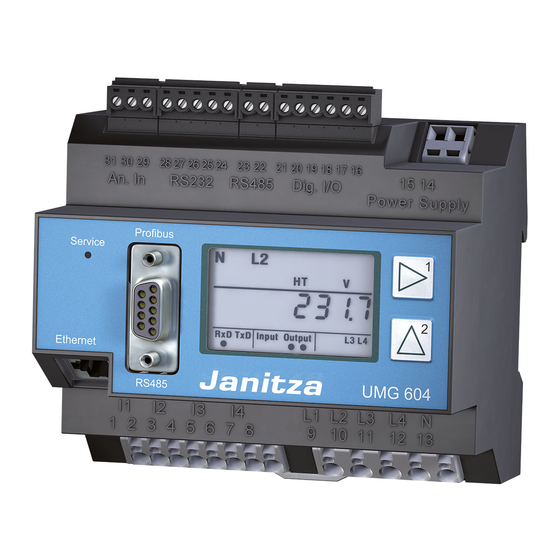
- Page 1 Network analyser UMG 604 Installation and Putting into Service Temperature measurement RS232 RS485 input 2 digital inputs 2 digital outputs Power supply voltage Profibus (optional) Ethernet (optional) Janitza electronics GmbH Vor dem Polstück 1 D-35633 Lahnau 4 x current 4 x voltage Support Tel.
-
Page 2: Table Of Contents
Contents General Information Installation Copyright Installed position Protected trademarks Power supply voltage Liability disclaimer Current measurement Comments on the manual Ammeter Meaning of the symbols used Direct measurement Inspection on receipt Voltage measurement Interfaces Scope of supply RS485 Available accessories RS485 profibus DP V0 slave Notes on Use Digital inputs and outputs... - Page 3 Contents System information Appendix Overrange Measured value displays Serial number Parameter list Date Declaration of conformity Firmware release Dimensioned drawings Time UMG604 connection example Service and maintenance Current measurement Network analyser Repair and calibration Voltage measurement Front film Power supply voltage Battery Quick Reference Instructions Firmware update...
-
Page 4: General Information
All trademarks and their resulting rights belong to the respective holders of these rights. Liability disclaimer Janitza electronics GmbH does not accept any responsibility whatsoever for errors or deficiencies within this manual and does not undertake any obligation to keep the content... -
Page 5: Meaning Of The Symbols Used
General Information Meaning of the symbols used The following pictograms are used in this manual: Dangerous voltage! Danger or risk of severe injury. Disconnect the system and device from the power supply before starting the work. Important! Please note follow documentation. -
Page 6: Inspection On Receipt
Inspection on receipt Inspection on receipt Please check the scope of supply for Fault free and safe use of this device requires completeness before you start installing the appropriate transport, proper storage, erection device. and assembly as well as careful operation and maintenance. -
Page 7: Scope Of Supply
Inspection on receipt Scope of supply Number Product No. Name 52 16 xxx UMG604 XX 33 03 0xx Installation and start-up instructions. 51 00 116 CD with the following content: - “GridVis” programming software, - Functional descriptions, GridVis, UMG604 .. - GSD file “0B41.GSD”... -
Page 8: Notes On Use
Product Description Notes on Use Please read these operating instructions and This device may be solely operated and all other publications which have to be used maintained by skilled persons. to work with this product (in particular for installation, operation or maintenance). Skilled persons are people who, on the basis of their relevant training and experience, are Note and follow all safety instructions as... - Page 9 Product Description Important! If the device is not operated according to the instruction manual, protection is no longer ensured and the device can cause hazards. Conductors made of individual wires must be fitted with wire end ferrules. Only pluggable screw terminals with the same number of poles (pins) and of the same type may be plugged together.
-
Page 10: Product Description
Product Description Product Description Intended use Measurement in medium and high-voltage The UMG604 is intended to be used for the systems takes place with current and voltage measurement and calculation of electrical transformers. Special safety requirements variables such as voltage, current, power, must be complied with for these, which are work, harmonic components, etc. -
Page 11: Umg604 Features
Product Description UMG604 features - Measurement in IT and TN systems, - 4 voltage measurement inputs - 4 current measurement inputs, - Continuous scanning of the voltage and current measurement inputs, - Energy measurement, measurement uncertainty class 0.5 for ../5A current transformers, - Energy measurement, measurement uncertainty class 1 for ../1A current transformers, - Registers more than 800 measured values (readings), - Fourier analysis 1st to 40th harmonic component for U, I, P (consumption/supply) and Q... -
Page 12: Methods Of Measurement
Product Description Methods of measurement Operating concept The UMG604 measures continuously and You can program the UMG604 and call up calculates all effective values over a 200 ms measured values in several ways. interval. • Directly at the device using 2 keys and the display. -
Page 13: Gridvis Programming Software
Product description GridVis programming software The UMG604 can be programmed and read RS232 ® out using the GridVis programming software included in the scope of supply. This requires a PC to be connected to the UMG604 via a serial interface/ethernet. Fig. -
Page 14: Three-Phase 4-Conductor Systems
Product Description Three-phase 4-conductor systems The UMG604 can be used in three-phase 4 conductor systems (TN, TT system) (50 Hz, 60 Hz) with earthed PEN conductor. The 66 V / 115 V bodies of the electrical system are earthed. 120 V / 208 V The conductor to neutral conductor voltage 127 V / 220 V may not exceed 300 V AC. - Page 15 Product Description 230/400V 50/60Hz 230/400V 50/60Hz Impedance AC/DC AC/DC Earthing the system Earthing the Voltage measurement Voltage measurement system Auxiliary power UMG604 Auxiliary power UMG604 Fig.15.2 Block diagram, UMG604 in IT system Fig.15.1 Block diagram, UMG604 in TN with N. system.
-
Page 16: Three-Phase 3-Conductor Systems
Product Description Three-phase 3-conductor systems The UMG604 can be used in unearthed three- phase 3 conductor systems (IT system). The 66 V conductor to conductor voltage may not 115 V exceed 480V AC (50 Hz, 60 Hz). 120 V The UMG604 is only suitable for environments 127 V in which the impulse voltage withstand 200 V... - Page 17 Product Description 230/400V 50/60Hz 400V 50/60Hz Impedance Impedance AC/DC AC/DC Earthing the Earthing the system system Voltage measurement Voltage measurement Auxiliary power Auxiliary power UMG604 UMG604 Fig.17.1 Block diagram, UMG604 in IT system Fig.17.2 Block diagram, UMG604 in IT system without N.
-
Page 18: Use
The UMG604 has a display, keys 1 and 2 and the Service key to make it easier to install and start up the UMG604 without a PC. Important parameters such current transformers and device address are included in the parameter list (see Appendix) and can be directly programmed at the device. -
Page 19: Display Mode
Display mode N L1 After the power supply is resumed the device is in Display mode. In Display mode you can use Keys 1 and 2 to page between the measured value displays. Use Key 1 to select the phase for the measured values. -
Page 20: Programming Mode
Programming mode The most important settings required for operation of the UMG604 can be displayed and changed in Programming mode. The parameter list in the Appendix contains the addresses for the most important settings. You can make further settings using the GridVis software included in the scope of supply. -
Page 21: Display Password
Display password You can program a 4-digit display password to make it difficult to accidentally change the programming data directly at the device. A display password is not set in the factory. Homepage password Content You can protect access to the UMG604's homepage via a password. -
Page 22: Installation
Installation Installation Installed position The UMG604 can be installed in control cabinets or in small distribution boards according to DIN 43880. It is mounted on a 35 mm mounting v according to DIN EN 60715. It can be installed in any position. Fig. -
Page 23: Power Supply Voltage
Installation Power supply voltage Power supply voltage A power supply voltage is required for Fuse operation of the UMG604. The type and amount of power supply voltage required is noted on the rating plate. Disconnecting device Before applying the power power supply voltage, ensure that the voltage and frequency match the information given on the rating plate! -
Page 24: Current Measurement
Installation Current measurement The UMG604 is designed for the connection of current transformers with secondary currents of ../1A and ../5A. Only alternating currents, not direct currents, can be measured. Each current measurement input can be permanently loaded with 6A or for 1 second with 100 A. - Page 25 Installation Fig. 23 Fig. 24 Current Current Fig. 25.1 Current measurement, connection Fig. 25.2 Current measurement, connection example for connection option 0. example for connection option 0. Fig. 22 Current Current Fig. 25.3 Current measurement, connection Fig. 25.4 Current measurement, connection example for connection option 0.
-
Page 26: Ammeter
Installation Ammeter Short-circuit current transformer con- If you not only want to measure the current nections! with the UMG604 but with an ammeter also, The secondary connections of the the ammeter must be connected in series to current transformer must be short- the UMG604. - Page 27 Installation Summation current measurement If the current is measured via two current Example transformers, the total transformation ratio of The current is measured via two current the current transformers must be programmed transformers. Both current transformers in the UMG604. have a transformation ratio of 1000/5A. The summation measurement is performed with a 5+5/5A summation current transformer.
-
Page 28: Direct Measurement
Installation Direct measurement Nominal currents up to 5 A can also be measured directly with the UMG604. In this case it must be noted that each current measurement input may be loaded continuously with 6 A or for 1 second with max 100 A. As the UMG604 does not have any integrated protection for the current measurement, this protection (e.g. -
Page 30: Voltage Measurement
Installation Voltage measurement The UMG604 is designed for the measurement of alternating voltages in 300 V systems in which category III overvoltages can occur. The UMG604 can only determine measured values if a measurement-current voltage greater than 10 Veff is applied to at least one voltage measurement input. - Page 31 Installation Voltage Voltage Voltage Fig. 31.1 Connection examples for voltage measurement in “three-phase 4-conductor systems”. (Connection option 0) Voltage Voltage Fig. 31.2 Connection examples for voltage measurement in “three-phase 3-conductor systems”. (Connection option 1) Important! Voltages above 300 VAC to earth Measuring-circuit voltages must be connected via voltage...
-
Page 32: Interfaces
Installation Interfaces RS232 Shielding You can use the connection cable included in A twisted-conductor and shielded cable must the scope of supply to connect the UMG604 be provided for connections via the RS232 to a PC. interface. The shielding at both ends of the The achievable distance between two devices cable must be connected to a large area of the with RS232 interface depends on the cable... - Page 33 Installation Com1 Mini Combicon, 5 pin D-sub, 9 pin, socket Fig. 33.2 Connector pin assignment for the PC connection cable. Fig. 33.1 Example, connecting a UMG604 to a PC via the RS232 interface.
-
Page 34: Rs485
Installation RS485 Terminating resistors Bus structure The cable at the start and end of a segment is All devices are connected in a bus structure terminated with resistors (120 ohm, 1/4 W). (line). Up to 32 stations can be connected together in a segment. - Page 35 Installation Shielding A twisted-conductor and shielded cable must be provided for connections via the RS485 interface. The shielding at both ends of the cable must be connected to a large area of the mounting plate or cabinet parts in order to achieve an adequate shielding effect.
-
Page 36: Rs485 Profibus Dp V0 Slave
Installation RS485 profibus DP V0 slave The profibus connection in the UMG604 is a 9 pin DSUB socket. We recommend use of a 9 pin profibus connector for the connection, e.g. as made by Phoenix, type “SUBCON- Plus-ProfiB/AX/SC” with product number 2744380. - Page 37 Installation Connecting the bus cables The incoming bus cable is connected to terminals 1A and 1B. The bus cable for the next device in the line is connected to terminals 2A and 2B. If there is not another device in the line the bus cable must be terminated with resistors (switch set to ON).
-
Page 38: Digital Inputs And Outputs
Installation Digital inputs and outputs Digital outputs The UMG604 has 2 transistor switching outputs. These outputs metallically separated from the analysis electronics via optocouplers. 24 V version The transistor switching outputs can switch direct current or alternating current loads. Each transistor switching output can switch 28 V and 30 mA maximum. - Page 39 Installation UMG604 UMG604 Digital outputs Digital outputs Digital Digital Output 1 Output 1 Digital Digital Output 2 Output 2 Fig. 39.1 Connection of alternating voltage Fig. 39.2 Connection of direct current relays relays to the digital outputs. to the digital outputs.
- Page 40 Installation Digital inputs UMG604 The UMG604 has 2 digital inputs to each of Digital inputs 1-2 which you can connect one transducer. Digital 24 V version (optional) Input 1 An input signal is detected at a digital input if a voltage of at least 10 V and maximum 28 V is 4,4k 3,9V...
- Page 41 Installation S0 pulse input UMG604 At each UMG604 with inputs for 24 V you can Digital inputs 1-2 also connect S0 pulse generators according to DIN EN 62053-31. You require only one external auxiliary voltage Digital of 20..28 V DC and one external 1.5 kohm Input 1 resistor each.
-
Page 42: Temperature Measurement Input
Installation Temperature measurement input Temperature sensors with a resistance range of 400 ohm to 4 kohm can be connected to the temperature measurement input. The total burden (sensor + cable) of 4 kohm may not be exceeded. Fig. 42.1 Example, temperature measurement with a KTY83. -
Page 43: Putting Into Service
Putting into Service Putting into Service Frequency measurement Applying the power supply voltage For the frequency measurement, the measured The power supply voltage level for the UMG604 voltage must be greater than 10 V in at least is given on the rating plate. Supply voltages one voltage measuring path (L-N). -
Page 44: Applying The Measuring-Circuit Voltage
Putting into Service Applying the measuring-circuit voltage The UMG604 is suitable for the measurement of voltages of up to 300 V AC to earth and 520 V AC conductor to conductor. UMG604 suitable measurement of direct voltages. Voltages above 300 VAC to earth must be connected via voltage transformers. -
Page 45: Phase Sequence
Putting into Service Phase sequence Applying the measuring-circuit current Check the direction of the voltage rotating field in the measured value display of the The UMG604 is designed for the connection UMG604. of ../1A and ../5A current transformers. A “right” rotating field usually exists. Only alternating currents, not direct currents, can be measured via the current measurement inputs. -
Page 46: Checking The Power Measurement
Putting into Service Checking the power measurement Short-circuit all current transformer outputs except for one and check the displayed power outputs. The UMG604 may only display one power output in the phase with a non short-circuited current transformer input. If this is not the case, check the connection of the measuring-circuit voltage and the measuring-circuit current. -
Page 48: Configuration
Configuration Configuration Current transformer ratio Address Current transformer values You can assign each of the 4 current transformer inputs its own current transformer L1 L2 L3 L4 (primary) ratio. A current transformer ratio of 5 A/5 A L1 L2 L3 L4 (secondary) is programmed in the factory for all 4 current transformer inputs. -
Page 49: Current Measurement Connection Options
Configuration Current measurement connection options Address Connection option The UMG604 recognises two connection 0 = Three current transformers. options for the current measurement. (Default factory setting) Connection option 0 1 = Two current transformers • Measurement via 3 current transformers (Aron circuit) in three-phase 4-conductor systems. -
Page 50: Voltage Transformer Ratio
Configuration Voltage transformer ratio Address Voltage transformer values You can assign each of the 4 voltage transformer inputs its own voltage transformer L1 L2 L3 L4 (primary) ratio. L1 L2 L3 L4 (secondary) A voltage transformer ratio of 400 V/400 V direct measurement is programmed in the L1 (primary) factory for all 4 voltage transformer inputs. -
Page 51: Voltage Measurement Connection Options
Configuration Voltage measurement connection options Address Connection option The UMG604 recognises two connection options for the voltage measurement. 0 = Three-phase 4-conductor systems (default factory Connection option 0 setting) • Direct measurement of the voltage in 3-phase 4-conductor systems. 1 = three-phase 3-conductor •... -
Page 52: Interfaces
Configuration Interfaces RS232 The UMG604 has 4 serial interfaces: - RS485 The following data must be programmed for - RS232 use of the RS232 interface: - Ethernet (optional) - Baud rate, - Profibus (optional) - Operating mode. All interfaces can be used simultaneously. Refer to the parameter list in the Appendix for the default factory setting and the setting RS485... -
Page 53: Ethernet (Optional)
Configuration Ethernet (optional) UMG604 Fixed IP address In simple networks without DHCP servers the network address must be set directly at the device. Patch cables BootP BootP allows fully automatic integration of a UMG604 in an existing network. BootP is an older protocol and does not have the functional Switch scope of DHCP. -
Page 54: Profibus (Optional)
Configuration Profibus (optional) Device master file Profibus profiles The device master file for the UMG604 is The UMG604 can manage 16 profibus profiles. called “0B41.GSD” and is included on the CD Each profibus profile contains 128 data bytes which belongs to the scope of supply. maximum. -
Page 55: Recordings
Configuration Recordings 2 recordings are preconfigured in the default factory setting of the UMG604. Recordings are adjusted and extended via “GridVis”. Recording 1 Recording 2 The following measured values are recorded The following measured values are recorded with the time base of 15 minutes: with the time base of 1 hour: Voltage L1-N Active power demand L1... -
Page 56: System Information
System information System information L1 L2 L3 L4 Overrange Overranges are displayed as long as they exist and cannot be acknowledged. An overrange exists if at least one of the four voltage or current measurement inputs lies outside their specified measuring range. RxD TxD Input Output L1 L2 L3 L4... -
Page 57: Serial Number
System information Serial number Firmware release RxD TxD Input Output L1 L2 L3 L4 RxD TxD Input Output L1 L2 L3 L4 Fig. Measured value display with serial number. Fig. Measured value display for the firmware release. Date Time RxD TxD Input Output L1 L2 L3 L4 RxD TxD... -
Page 58: Service And Maintenance
Service and maintenance Service and maintenance operation. A warranty will be provided for The device is subjected to various safety unopened devices only. checks before delivery and marked with a seal. If a device is opened, the safety checks Disposal must be repeated. -
Page 59: What To Do In Case Of Errors
Service and maintenance What to do in case of errors Possible error Cause Remedy No display. External fusing for the power Replace fuse. supply voltage has tripped. Device is defective. Send device to the manufacturer for repair. No current display. Measurement voltage is not Connect measuring-circuit... - Page 60 Service and maintenance Possible error Cause Remedy Displayed voltage Measurement in the wrong phase. Check connection and correct if is too small or too necessary. large. Voltage transformer incorrectly Read out and program the voltage programmed. transformer transformation ratio at the voltage transformer. Displayed voltage is Overrange.
- Page 61 Service and maintenance Possible error Cause Remedy Active power too The programmed current Read out and program the current small or too large. transformer transformation transformer transformation ratio at the ratio is incorrect. current transformer. The current path is assigned Check connection and correct if to the wrong voltage path.
-
Page 62: Technical Specifications
Technical specifications Technical specifications General information Net weight : 350g Device dimensions : approx l=107.5 mm, b=90 mm, h=60 mm (according to DIN 43871:1992) Housing flammability class : UL94V-0 Installed position : any Fixing/mounting : 35 mm top hat rail (according to IEC/EN 60999-1, DIN EN 50022) Battery : Type VARTA CR2032, 3 V, Li-Mn... -
Page 63: Power Supply Voltage
Technical specifications Power supply voltage The power supply voltage must be connected to the UMG604 via a UL listed fuse : 6A, Type C Overvoltage category : 300 V CATIII Nominal range : 123V. 240 V (45-65 Hz) or DC 175 V .. 340V Operating range : +-10% of AC nominal range : +-10% of DC nominal range... -
Page 64: Measurement Uncertainty
Technical specifications Measurement uncertainty The measurement uncertainty of the UMG604 applies to use of the following measuring ranges. The measured value must lie within the given limits. Outside these limits the measurement uncertainty is unspecified. Measured value Measurement uncertainties Voltage ±(0.2% rdg + 0.02% rng) Current L ±(0.2% rdg + 0.05% rng) -
Page 65: Measuring Ranges
Technical specifications Measuring ranges Measured value Measuring ranges (rng) Resolution Sinusoidal variables Voltage L-N ... 600 Vrms 0.01V Voltage L-L ... 1000 Vrms 0.01V Current 0,001 ... 7.5 Arms 0.1 mA Frequency of the fundamental component 45 Hz..65 Hz 0.001 Hz 1) The UMG604 can only determine measured values if a measurement-current voltage greater than 10 Veff is applied to at least one voltage measurement input. -
Page 66: Inputs And Outputs
Technical specifications Inputs and outputs 24 V version (optional) 2 digital inputs Pulse input (S0) Maximum counting frequency : 20 Hz Switching input Response time (Jasic program) : 200 ms Input signal applied : 18V. 28 V DC (typically 4 mA) Input signal not applied : 0 .. -
Page 67: Temperature Measurement Input
Technical specifications Temperature measurement input Update time : approx 200 ms Connectable sensors : PT100, PT1000, KTY83, KTY84 Total burden (sensor + cable) : max 4 kohm Sensor type Temperature range Resistance range Measurement uncertainty KTY83 -55 ° .. +175 °C 500 ohm .. -
Page 68: Interfaces
Technical specifications Interfaces RS232 : 5 pin screw-type terminals. Protocol : Modbus RTU/slave Transfer rate 9600 bps, 19.2 kbps, 38.4 kbps, 115.2 kbps RS485 : 2 pin screw-type terminals. Protocol, modbus RTU : Modbus RTU/slave, modbus RTU/master Transfer rate : 9.6 kbps, 19.2 kbps, 38.4 kbps, 76.8 kbps, 115.2 kbps, 921.6 kbps RS485 (optional) : Connector, SUB D 9 pin... - Page 69 Appendix Measured value displays You can have the following measured values shown on the display, with the default factory setting, using keys 1 and 2. The measured value names used are abbreviated and have the following mean- ing: Active power demand = active power demand, imported supply Reactive power = reactive power, inductive...
- Page 70 Appendix Parameter list Default Add Name Setting range Units setting Current transformer, primary, L1..L4 0 .. 1000000 Current transformer, secondary, L1..L4 1 .. 5 Voltage transformer, primary, L1..L4 0 .. 1000000 Voltage transformer, secondary, L1..L4 1 .. 400 Current transformer, primary, L1 0 ..
- Page 71 Appendix Default Add Name Setting range Units setting Automatically get TFTP configuration file 0 .. 9999 0 = switched off x = file number TFTP error handling 0 .. 1 0 = In the event of an error the Configuration menu appears in the UMG604.
- Page 72 Appendix Default Add Name Setting range Units setting Device address, modbus/profibus 1 .. 255 Baud rate, RS232 0 .. 4 0 = 9600 bit/s 1 = 19200 bit/s 2 = 38400 bit/s 3 = 57600 bit/s 4 = 115200 bit/s Baud rate, RS485 0 ..
- Page 73 Appendix Default Add Name Setting range Units setting DHCP mode 0, 1, 2 0 = fixed IP 1 = BootP 2 = DHCP-Client IP address, xxx --- --- --- 0 .. 255 IP address, --- xxx --- --- 0 .. 255 IP address, --- --- xxx --- 0 ..
- Page 74 Appendix Default Add Name Setting range Units setting 1 .. 31 Month 1 .. 12 Year 1 .. 9999 xxxx Hour 0 .. 23 Minute 0 .. 59 Second 0 .. 59 Accept date and time 0, 1 1 = accept set data Device password 0 ..
- Page 75 Appendix Declaration of conformity The UMG604 fulfils the safety requirements of: Directive 89/336/EEC in conjunction with DIN EN 61326-1:2006 as well as Directive 2006/95/EC in conjunction with EN 61010-1 (2002-08) Safety requirements Safety requirements for electrical instrumentation, control and laboratory equipment : EN 61010-1 08:2002, IEC 61010-1:2001 Protection class : II (device without protective conductor)
- Page 76 Appendix Dimensioned drawings Front view Side view...
- Page 77 Appendix UMG604 connection example Power supply voltage Network analyser Current measurement Voltage measurement...
- Page 78 Quick Reference Instructions Quick Reference Instructions Adjusting the primary current You have three current transformers of the same type with a current transformer ratio of 200 A/5 A. You would like to program the primary current with 200 A. To do this you must enter the value 200 for the primary current in the address 000. The secondary current is preset to 5 A in address 001 in the factory.
Need help?
Do you have a question about the UMG 604 and is the answer not in the manual?
Questions and answers