Table of Contents
Advertisement
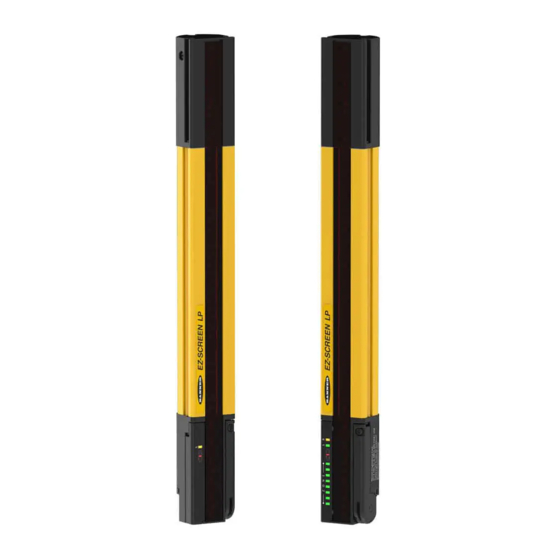
Low-Profile Safety Light Screen
Low-Profile Safety Light Screen
Features
A two-piece optoelectronic safeguarding device
•
Creates a screen of synchronized, modulated infrared
•
sensing beams that extend from end to end of the
housing (no "dead" zone)
Low-profile, compact package for smaller production
•
machines, robust for large power presses
Choose standard or cascadeable models
•
14 mm or 25 mm resolution; defined areas from 270 to
•
1810 mm 0
to
)
00 mm to m
to
') sensing range
•
Easily configured reduced resolution and fixed blanking.
•
Remote Teach of fixed blanking option on cascade
models.
Zone and Status indicators plus digital display to indicate
•
number of beams blocked, detailed diagnostics
Highly immune to EMI, RFI, ambient light, weld flash, and
•
strobe light
Selectable 1-ch, 2-ch, or no external device monitoring
•
Selectable auxiliary output option to monitor the state of
•
the OSSDs or monitor receiver and emitter lockouts
Selectable emitter test option simulates a "blocked"
•
condition
Vibration-tolerant, factory burned-in emitter and receiver
•
circuitry for toughness and dependability
FMEA tested to ensure control reliability
•
Up to four pairs of SLPC.. model emitters and receivers
•
can be cascaded
Safety PLC input compatible (per OSSD specifications)
•
Buy: www.ValinOnline.com | Phone 844-385-3099 | Email: CustomerService@valin.com
EZ-SCREEN
Instruction Manual
Original Instructions
Section 1 Introduction . . . . . . . . . . . . . . . . . . . . . . . . . . . . . Page 1
Section 2 Components and Specifications . . . . . . . . . . . . . . Page 6
Section 3 Installation and Alignment . . . . . . . . . . . . . . . . . . Page 21
Section 4 System Operation . . . . . . . . . . . . . . . . . . . . . . . . Page 42
Section 5 Troubleshooting and Maintenance . . . . . . . . . . . Page 48
Section 6 Checkout Procedures . . . . . . . . . . . . . . . . . . . . . Page 53
Section 7 Cascadeable EZ-SCREEN LP . . . . . . . . . . . . . . Page 55
LP
®
Section Contents
Advertisement
Table of Contents

Related Manuals for Banner EZ-SCREEN LP


Summary of Contents for Banner EZ-SCREEN LP
-
Page 1: Table Of Contents
Section 6 Checkout Procedures ..... Page 53 FMEA tested to ensure control reliability • Section 7 Cascadeable EZ-SCREEN LP ....Page 55 Up to four pairs of SLPC.. model emitters and receivers •... - Page 2 7. Cascadeable EZ-SCREEN LP ....... . .55 7.1 Overview of Cascading.
-
Page 3: Section 1 Introduction
(FSDs) that control the primary control elements (MPCEs), which immediately stop the motion of the guarded machine. EZ-SCREEN LP is extensively FMEA (Failure Mode and Effects Analysis) tested to establish an extremely high degree of confidence that when properly installed, no system component will (even if it should fail) cause a failure to danger. -
Page 4: Applications And Limitations
“stop” signal to be sent to the guarded machine and puts the appropriate standard). EZ-SCREEN LP into a Lockout condition. If an EZ-SCREEN LP is installed for use as a perimeter guard Recovery from this type of Lockout condition requires: (i.e., where a pass-through hazard may exist), the dangerous • r eplacement of the failed component (to restore redundancy) -
Page 5: Operating Features
(and all beams are clear), or following a blocked beam (see emitter, simulating an interruption of one or more light beams. Section 4.5). This function may be useful for EZ-SCREEN LP setup and to verify machine control circuit operation. WARNING . . . - Page 6 Diagnostic Display Diagnostic Display Zone Indicators (each shows status of approx. 1/8 of the total beams) Zone 1 Indicator (indicates beam synchronization status) Figure 1-3. EZ-SCREEN LP emitter and receiver status indicators Buy: www.ValinOnline.com | Phone 844-385-3099 | Email: CustomerService@valin.com...
- Page 7 Reset Routine A DIP switch can be used to invert the seven-segment display. The EZ-SCREEN LP requires a manual reset to clear a Power- This makes the display “right reading” when an emitter and Up Lockout or Latch condition, and after correcting the cause receiver are mounted with the QD connector ends up (upside of a Lockout condition.
-
Page 8: Section 2 Components And Specifications
Components and Specifications Instruction Manual 2. Components and Specifications An EZ-SCREEN LP “System” refers to a compatible emitter and receiver (equal length and resolution; available separately or in RD cordset with pairs), and cordset(s) for each. It also refers to the emitters and flying leads receivers in a cascade, and their cabling. -
Page 9: Emitter And Receiver Models (Non-Cascadeable) - 14 Mm Resolution
QD models (e.g., SLPE14-270P8) have yellow PVC cable and black PVC QD overmold. For other models, see below.* See the Banner Safety catalog or call the factory for kit model numbering scheme. Order one machine interface cordset for each emitter or receiver; see Section 2.3.**... -
Page 10: Emitter And Receiver Models (Non-Cascadeable) - 25 Mm Resolution
QD models (e.g., SLPE25-270P8) have yellow PVC cable and black PVC QD overmold. For other models, see below.* See the Banner Safety catalog or call the factory for kit model numbering scheme. Order one machine interface cordset for each emitter or receiver; see Section 2.3.**... -
Page 11: Cordsets
3rd, and 4th sensors in a cascade (see Figure 7.8 for other options) Model Length Wire Termination 0.3 m (1') DELPE-81D Figure 2-3. EZ-SCREEN LP connection options 1 m (3.3') RD-style DELPE-83D 2.5 m (8.2') 8-conductor removable DELPE-88D RD to Flying Leads Cordsets 4.6 m (15.1') - Page 12 * * The European M12 Specification pin assignment and color codes are listed as a customer courtesy. The user must verify suitability of these cables for each application. Splitter Cordsets Used for easy interconnection between an EZ-SCREEN LP receiver and its emitter, providing a single “homerun” cable (see Figure 3-22). Model DEE2R-.. double-ended cordsets may be used to extend the QD trunk or either branch.
-
Page 13: Accessories
Contactors The N.C. contacts are to be used in an external device monitoring (EDM) circuit. If used, two contactors per EZ-SCREEN LP system are required. (See Figure 3-21.) See data sheet p/n 111880 for additional options and more information. 10 amp positive-guided contactor (3 N.O., 1 N.C.) 11-BG00-31-D-024 18 amp positive-guided contactor (3 N.O., 1 N.C.) - Page 14 Components and Specifications Instruction Manual Muting Modules Provide muting capability for the EZ-SCREEN LP. See Banner manuals p/n 63517 or 116390 for further information and additional cabling options. 2 NO safety outputs (6 amps), 2 or 4 muting inputs, SSI, MMD-TA-11B override input;...
- Page 15 LPSS-1810 EZ-LIGHT™ for EZ-SCREEN Provides clear, 360° indication of the EZ-SCREEN LP receiver’s output status. Use with a CSB splitter cable and optional DEE2R double- ended cables. See data sheet 121901 for more information, or call for additional options. Models...
- Page 16 EZ-SCREEN LP Overview Components and Specifications Components and Specifications Instruction Manual Accessory Mounting Brackets See Section 2.5 for standard brackets (included with sensors). LPA-MBK-120 LPA-MBK-13 • F ixed angled “L” bracket for two cascaded • A daptor for side-mount bracket LPA-MBK-12 emitters or receivers; uses clamps from side- • R eorients sensor rotation by 90° (+10°, ∆0- °) mount bracket LPA-MBK-12.
- Page 17 Instruction Manual MSM Series Corner Mirrors Rear-surface glass mirrors rated at 85% efficiency. The total sensing range decreases by approximately 8% per mirror. See mirror data sheet P/N 43685 or the Banner Safety catalog M4 x 10 mm Screw for further information.
-
Page 18: Replacement Parts
SSM mirror bracket kit. Includes 2 replacement brackets for one mirror. SMA-MBK-1 2.6 Literature The following documentation is supplied with each EZ-SCREEN LP receiver. Additional copies are available at no charge; contact the factory or visit anner nginering website. Description... -
Page 19: Specifications
Models longer than 690 mm also include additional side-mount bracket(s) for center support. Mounting brackets are 14-gauge/1.9 mm cold-rolled steel, black zinc finish. See Section 2.3 for recommended cables. If other cables are used with the EZ-SCREEN LP, the user Cables and Connections must verify suitability of these cables for each application. - Page 20 EZ-SCREEN LP Overview Components and Specifications Components and Specifications Instruction Manual 2.7.2 Emitter Specifications 24V dc ±15% (use a SELV-rated supply according to EN IEC 60950) Supply Voltage at the Device (The external voltage supply must be capable of buffering brief mains interruptions of 20 ms, as specified in IEC/EN 60204-1.)
- Page 21 Two redundant solid-state 24V dc, 0.5 A max. sourcing OSSD (Output Signal Switching Device) safety Output Signal Switching Devices outputs. (Use optional interface modules for ac or larger dc loads.) (OSSDs) Capable of the Banner “Safety Handshake” (see Section 1.1). ON-State voltage: OFF-State voltage: 1.2V dc max. (0-1.2V dc) Max. load capacitance: 0 Max.
- Page 22 EZ-SCREEN LP Overview Components and Specifications Components and Specifications Instruction Manual 20.0 [0.79"] 10.0 [0.39"] 26.0 [1.02"] 28.0 [1.10"] 9.4 [0.37"] R13 mm (0.5") minimum bend See page 19 for detailed bracket dimensions. Emitter / Receiver Housing Length Distance Between Bracket Holes Defined Area †...
-
Page 23: Section 3 Installation And Alignment
System detected (by blocking a sensing beam), the EZ-SCREEN LP will cannot provide the protection for which it was designed. send a stop signal to the machine, causing it to stop before the Installation must be performed by a Qualified Person, as defined person can reach any machine hazard point. - Page 24 Ds = 63 x (0.32 + 0.0165) + 3.6 = 24.8" S = (1600 x 0.3365) + 160 = 698.4 mm Mount this EZ-SCREEN LP emitter and receiver so that no part of Mount this EZ-SCREEN LP emitter and receiver so that no part of the defined area will be closer than 698.4 mm to the closest...
- Page 25 ANSI B11 series or other appropriate standards. Failure to Perimeter Guarding do so could result in serious injury or death. If an EZ-SCREEN LP System is installed in an application that results in a pass-through hazard (e.g., perimeter guarding), either the 3.1.4 Supplemental Safeguarding...
- Page 26 (e.g., both cabled ends “up”). Failure to orient them properly will Figure 3-5. Examples of correct emitter / receiver orientation impair the performance of the EZ-SCREEN LP and will result in incomplete guarding, and could result in serious bodily injury or death.
- Page 27 (see Figure defined area, and prevent its detection by the EZ-SCREEN LP 3-6). System. Perform the trip test, as described in Section 3.4.4, to detect such reflection(s) and the resultant optical short circuit.
- Page 28 7 m (23') Range To further aid in avoiding crosstalk, the sensors feature two See the specific mirror data sheet or the Banner Safety Catalog for further information. selectable scan codes. A receiver set to one scan code will not “see”...
-
Page 29: Mechanical Mounting Procedure
EZ-SCREEN LP Installation and Alignment Overview Instruction Manual 3.2 Mechanical Mounting Procedure Emitter a. Two pairs Once the mechanical layout considerations of Section 3.1 are Receiver in a horizontal Receiver addressed, mount the sensors and route the cables. plane Emitter 3.2.1 Sensor Mounting... - Page 30 Installation and Alignment EZ-SCREEN LP Overview Instruction Manual End-Mount Brackets Side-Mount Brackets (2 supplied with each emitter and receiver) (2 or more* supplied with each emitter and receiver ) Sensors may be mounted with all side-mount brackets, or a combination of side-mount and end-mount brackets.
- Page 31 EZ-SCREEN LP system. of electrical conduit. See Section 2.3 for selection of Banner- It is good wiring practice (and may be required by code) to supplied cables.
-
Page 32: Initial Electrical Connections
Following relevant electrical standards. standards and wiring codes, such as the NEC, NFPA79 or Make no more connections to the EZ-SCREEN LP System than IEC60204-1, always connect earth ground (green/yellow are described in Sections 3.3 through 3.5.5 of this manual. -
Page 33: Light Screen Initial Checkout
EZ-SCREEN LP Installation and Alignment Overview Instruction Manual 2. Verify that power is removed from the EZ-SCREEN LP 3.4 Light Screen Initial Checkout System and from the guarded machine and that the OSSD safety outputs are not connected. Remove all obstructions The initial checkout procedure must be performed by a Qualified from the light screen. - Page 34 Installation and Alignment EZ-SCREEN LP Overview Instruction Manual 4. Optical Alignment CAUTION: E nsure that no individuals are exposed to any Straight Edge C1 or C2 hazard if the OSSD outputs turn ON when the emitter and receiver become aligned.
- Page 35 Optical Alignment Procedure with Mirrors Use Reduced Resolution and Fixed Blanking only when EZ-SCREEN LP sensors may be used with one or more corner necessary. Any holes created in the defined area either must be mirrors for guarding more than one side of an area. The models completely filled by the blanked object or the safety (minimum) MSM...
- Page 36 The zone indicators remain active and denote the location of blocked beams. 2. Verify that the EZ-SCREEN LP is in Run mode with the 8. To teach the blanked beams, re-configure DIP switches for Green Status indicator ON (or flashing if reduced resolution is normal operation (see Table 4-1 and Figure 4-1).
-
Page 37: Electrical Interface To The Guarded Machine
System. WARNING . . . OSSD Interfacing If this occurs, the EZ-SCREEN LP cannot be relied on to stop dangerous machine motion when a person or object enters the To ensure proper operation, the EZ-SCREEN LP OSSD output defined area. - Page 38 OSSD Single-channel control uses a series connection of FSD contacts outputs of the EZ-SCREEN LP. FSDs can also be used to to form a safe switching point. After this point in the machine’s...
- Page 39 Two-channel monitoring is also the default setting and has the monitoring (EDM). advantage of additional diagnostic capability that can identify For the EZ-SCREEN LP external device monitoring to function which specific element that has slowed or failed. properly, each device must include a normally closed (N.C.), forced-guided (mechanically linked) contact that can accurately reflect the status of the device.
-
Page 40: Preparing For System Operation
EDM connections have been made to the monitor contacts must be closed before the EZ-SCREEN LP can machine to be controlled, the EZ-SCREEN LP is ready for testing be reset and the OSSDs can turn ON. Regardless of the state of in combination with the guarded machine. - Page 41 Or/Bk CSB.. Splitter Model CSB.. splitter cordsets and DEE2R.. Cordset double-ended cordsets allow easy interconnection between an EZ-SCREEN LP receiver and emitter, providing a single “homerun” cordset (see Section 2.3 Cordsets). See table below or Gn/Ye Section 2.3 for pinout...
- Page 42 Ground face view † Bu (#6) 0V dc Bk (#5) OSSD1 NOTE: EZ-SCREEN LP receiver DIP switches are Wh (#4) OSSD2 configured for “Trip” (T) output and 2-channel EDM. If the Auxiliary output is to be used, Vi (#8) Reset*...
- Page 43 ** Trip (auto reset) — Not connected *** Other interfacing modules and solutions available, see See Table 2.2 for further QDE-8D cable † information. Section 2.4 or the Banner Safety Catalog. MPCE † See Table 2.3 for further cordset information. Machine MPCE...
-
Page 44: Section 4 System Operation
If the corresponding pairs of DIP switches are not set identically, the EZ-SCREEN LP will not operate. Power to the EZ-SCREEN LP receiver should be OFF when changing DIP switch settings (other than Scan Code) or a Lockout will occur. -
Page 45: Reset Procedures
This will hinder a reset while If the switches are set for trip output (T), the EZ-SCREEN LP will the key is under the control of an individual, but must not be auto-reset after a blocked condition. -
Page 46: Status Indicators
System Operation EZ-SCREEN LP Overview Instruction Manual Lockout status (flashing Red). A 7-segment Diagnostic Display 4.4 Status Indicators indicates the receiver’s trip (–) or latch (L) configuration setting and displays a specific error code when the receiver is in A variety of status indicators are clearly visible on each emitter Lockout. - Page 47 EZ-SCREEN LP System Operation Overview Instruction Manual Operating Reset OSSD Status Indicator Zone Indicators* 7-Segment Diagnostic Display Mode Indicator Outputs Scan code flash 3x – sequentially Power-up Single-Flash Red All Single-Flash Red Alignment Mode – Zone 1 Red* Beam 1 Blocked Others OFF Alignment Mode –...
- Page 48 System Operation EZ-SCREEN LP Overview Instruction Manual Status Indicators for Cascaded Applications Table 4-2. EZ-SCREEN LP Cascade Diagnostics When multiple light screens are cascaded, some unique Reset Status indications may occur, as indicated in Figure 4-7 and table 4-2. Condition...
-
Page 49: Normal Operation
ON only when all beams are clear and sync pattern from the emitter. If the receiver is aligned and after a manual reset. The EZ-SCREEN LP will wait for a manual receives the proper sync pattern, it enters Run mode and begins reset;... -
Page 50: Section 5 Troubleshooting And Maintenance
Power failures and Lockout conditions are indication of a problem and must be investigated immediately by a Qualified Person. A Lockout condition causes all of the EZ-SCREEN LP’s OSSD Attempts to continue to operate machinery by bypassing the outputs to turn or remain OFF, sending a stop signal to the EZ-SCREEN LP or other safeguards is dangerous and could guarded machine. - Page 51 EZ-SCREEN LP Troubleshooting and Maintenance Overview Instruction Manual 5.1.1 Receiver Error Codes Multiple-digit codes are sequential, followed by a pause. Diagnostic Error Description Cause of Error and Appropriate Action Display • D isconnect the OSSD loads and reset the receiver. Output Error • I f the error clears, the problem is in the OSSD load(s) or in the load wiring.
- Page 52 Troubleshooting and Maintenance EZ-SCREEN LP Overview Instruction Manual 5.1.1 Receiver Error Codes (continued) Diagnostic Error Description Cause of Error and Appropriate Action Display EDM 2 Error • V erify that the EDM wiring is correct and that the external devices meet the EDM 2 configuration not valid (wiring or requirements described in Section 3.5.3.
-
Page 53: Test Mode
EZ-SCREEN LP Troubleshooting and Maintenance Overview Instruction Manual 5.1.2 Emitter Error Codes Multiple-digit codes are sequential, followed by a pause. Diagnostic Error Description Cause of Error and Appropriate Action Display* Emitter Error • R eset the emitter by either performing a reset or cycling power to the emitter (see This error can occur either due to Section 4.3). -
Page 54: Electrical And Optical Noise
Minneapolis, MN 55441 wiring, can inject noise into the System. It is good wiring practice (and may be required by code) to isolate EZ-SCREEN LP wires from high-voltage wires. The Banner model BT-1 beam tracker (see Section 2.4) is a... -
Page 55: Section 6 Checkout Procedures
11. machine as described in Section 3.5), or whenever changes 8. Apply power to the EZ-SCREEN LP. Verify that power to the are made to the System (either a new configuration of the EZ-SCREEN LP or changes to the machine). A Qualified guarded machine is OFF. -
Page 56: Shift/Daily Checkout
Refer to the procedure contained on the Semi-Annual Checkout card (Banner part number 140047) in the lit packet 14. Remove electrical power to the EZ-SCREEN LP. Both OSSD included with the receiver. If the Semi-Annual Checkout card outputs should immediately turn OFF, and the machine... -
Page 57: Section 7 Cascadeable Ez-Screen Lp
7. Cascadeable EZ-SCREEN LP 7.1 Overview of Cascading 7.1.1 System Components and Specifications EZ-SCREEN LP emitters and receivers are also available in A multiple-light screen cascaded EZ-SCREEN LP system cascadeable models. These models can be used as stand-alone includes compatible emitter/receiver pairs (up to four), a light screens, or can be cascaded up to four pairs in one system;... -
Page 58: Cascadeable Emitter And Receiver Models - 14 Mm Resolution
Only standard yellow housing models are listed. Pigtail QD models (e.g., SLPCE14-270P8) have yellow PVC cable and black PVC QD overmold. For other models, see below.* See the Banner Safety catalog or call the factory for kit model numbering scheme. Order one machine interface cordset for each “master” emitter or receiver; see Section 2.3.** For interconnections between cascaded emitters and receivers, use DELP.. -
Page 59: Cascadeable Emitter And Receiver Models - 25 Mm Resolution
Only standard yellow housing models are listed. Pigtail QD models (e.g., SLPCE14-270P8) have yellow PVC cable and black PVC QD overmold. For other models, see below.* See the Banner Safety catalog or call the factory for kit model numbering scheme. Order one machine interface cordset for each “master” emitter or receiver; see Section 2.3.** For interconnections between cascaded emitters and receivers, use DELP.. -
Page 60: Determining Interconnect Cordset Lengths
(e.g., the front and back of a combinations are possible; please call factory for assistance. power press) and uses four EZ-SCREEN LP pairs to create two As the machine interface Cordset lengthens, the voltage drop “L”-shaped sensing fields. -
Page 61: Response Time For Cascaded Light Screens
DELP-8..D cordset screen’s separation (safety) distance. For cascaded (or “daisy- chained”) EZ-SCREEN LP systems, that response time is dependent on the number of light screens, the number of beams in the light screens, and their positions in the cascade. It can be calculated easily, in two ways: • I ndividually for each light screen in the cascade (safety... - Page 62 = 46 ms Control (cascade2) Position #3: Tr = Tr + 4 ms EZ-SCREEN LP Cascade Overall System Response (for system as shown)* (cascade3) 11 + [(4 – 1) × 2 ms] Position #4: Tr = Tr + 6 ms...
-
Page 63: Cascaded Sensor Configuration Settings
OSSD outputs. All other One or more areas within any cascaded EZ-SCREEN LP sensor pair can be blanked out, just as with other EZ-SCREEN LP light receivers in the cascade must be set for trip mode and screens. -
Page 64: Configuration For Cascaded Operation
E-stop w/closed contacts: “1CE” E-stop w/open contacts: “1CO” If Cascade Input is used for an Emergency Stop function, do not mute or bypass the safety outputs (OSSDs) of the EZ-SCREEN LP. • O ther receivers sequentially display “1C” ANSI/NFPA79 and IEC 60204-1 require that the Emergency Stop function remain active at all times. - Page 65 • W henever two or more E-stop switches are connected “armed” position. Once activated, the E-stop switch must open to the same EZ-SCREEN LP receiver, the contacts of the its contacts and return to the closed-contact position only after E-stop switches must be connected together in series. This series deliberate action (such as twisting, pulling, or unlocking).
-
Page 66: Positive-Opening Safety Interlock Switches
(see the Banner Safety Catalog for examples). Please reference OSHA CFR1910.217, ANSI B11 standards, or In addition, the switches must be mounted in a “positive mode”... - Page 67 Figure 7-9), a faulty switch will be detected if it fails to switch as the guard opens. In this case, the EZ-SCREEN LP 2. Non-detection of a failure. If a good guard is opened, the will de-energize its OSSD output and disable its reset function EZ-SCREEN LP de-energizes its outputs (a normal response).
-
Page 68: Remote Fixed Blanking
One or multiple areas is required on other receivers in the cascade string, see Section within an EZ-SCREEN LP sensor pair may be “blanked out,” 3.4.3 for DIP switch configuration information. with a minimum of one beam between two blanked areas. The... - Page 69 EZ-SCREEN LP Cascadeable EZ-SCREEN Overview Instruction Manual Remote Fixed Blanking Programming Procedures Important: 1.The first sensing beam (synchronization beam) at the display Prior to performing these procedures, install the EZ-SCREEN end of the sensor must remain clear. LP per Section 3 of this document, including all other DIP switch configuration settings (T/L, RR, and Scan Code).
- Page 70 Instruction Manual •• ••• •• • ••••••• ••••••• •••••••••••• • ••••• ••••• • ••• ••• •• ••• ••• • ••• • •• ••••••••••••••••••••••••••••••••••••••••••••••••••••••••••••••••••••• Obstruction is relocated or cleared with EZ-SCREEN LP power OFF. • Clearing an Error Code 10 “Fixed Blanking Error” (begin at step #5, with the programming key switch in the Run position) •...
-
Page 71: Appendix A. Bracket Assembly Instructions
Appendix A. Bracket Assembly Instructions The screwdriver provided with the EZ-SCREEN LP is intended for access to the DIP switches and for preassembly of the mounting bra kets inal assembl ti htenin ) of the mo ntin bra ket sho l be a omplishe... -
Page 72: Glossary Of Terms
Glossary EZ-SCREEN LP Overview Instruction Manual Glossary of Terms The following terms are used often in this manual. Where CSA: Abbreviation for Canadian Standards Association, a testing possible, this manual uses definitions from the U.S. and agency similar to Underwriters Laboratories, Inc. (UL) in the international product performance standards that govern the United States. - Page 73 Lockout condition are permitted; failures which cause an unsafe object that a safety light screen system can reliably detect. condition (a failure to danger) are not. Banner safety products Objects of this diameter or greater will be detected anywhere in are extensively FMEA tested.
- Page 74 When inserted into any part of the defined area, it will then insert a new part and start another cycle. The presence- place a system into a Trip or Latch condition. Banner supplies sensing device continually guards the machine. Single-break specified test pieces with each system.
Need help?
Do you have a question about the EZ-SCREEN LP and is the answer not in the manual?
Questions and answers