
Related Manuals for Banner PTL110S


Summary of Contents for Banner PTL110S
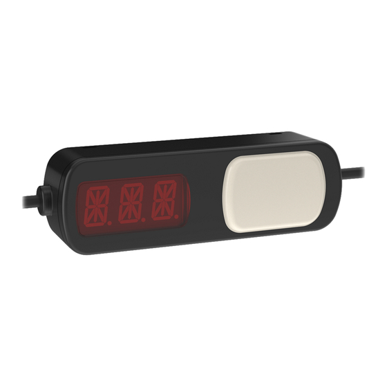
- Page 1 PTL110S Pick-To-Light Devices Instruction Manual Original Instructions 206185 Rev. A 16 January 2019 © Banner Engineering Corp. All rights reserved 206185...
-
Page 2: Table Of Contents
PTL110S Pick-To-Light Devices Contents 1 Models .................................... 3 1.1 Overview of the PTL110S ................................3 1.1.1 Communications ..................................3 1.1.2 Common ID ..................................... 4 1.1.3 Timeout ....................................4 2 Configuration Instructions .............................. 5 2.1 Operational Modes ..................................5 2.2 Indicator Touch Surface and Optical Sensor Operation .........................6... -
Page 3: Models
The touch sensor can be disabled. Sensor Optical sensor models contain a Banner fixed field optical sensor for actuation. Two distance models are available, 100 mm (4 in) and 200 mm (8 in). The optical sensor can be disabled. -
Page 4: Common Id
Modbus network communicate. When a device is activated, it responds to the common ID. Through the common ID, the master can read the device's slave ID stored in register 7940. When polling the common ID, Banner recommends reading a minimum of the slave ID register 7940 and the output state register 7941. These registers hold the slave ID of the device that was activated and the status of what was activated on the device. -
Page 5: Configuration Instructions
6354 Registers 6345 to 6354 define the Secondary Acknowledge State * Refer to PTL110S Register Map for descriptions and enumerations of these visual states 0 = Wait. Device is waiting and should not be triggered. If the device is triggered it Moves a device from the Wait state to the Job will move to the Mispick state. -
Page 6: Indicator Touch Surface And Optical Sensor Operation
PTL110S Pick-To-Light Devices Registers Animation Description Indicator off Steady Color 1 solid on at defined intensity Flash Color 1 flashes at defined speed, intensity and pattern Two Color Flash Color 1 and color 2 flash alternatively at defined speed, intensities and pattern... -
Page 7: 7-Segment Display Operation
PTL110S Pick-To-Light Devices Output Registers Register Description Values Holds the latched statuses of the inputs. This register is designed to be 0 = None activated cleared by the master upon receipt. If the register is not cleared, the Output 7941... - Page 8 PTL110S Pick-To-Light Devices Registers Description Values Value Character Value Character Value Character Value Character 0x30 0x61 0x6B 0x75 0x31 0x62 0x6C 0x76 0x32 0x63 0x6D 0x77 0x33 0x64 0x6E 0x78 0x34 0x65 0x6F 0x79 0x35 0x66 0x70 0x7A 0x36 0x67...
-
Page 9: Maximum System Size
PTL110S Pick-To-Light Devices 2.4 Maximum System Size The maximum size of the system depends on several factors. Changes to any of these items will affect the maximum number of devices that can be used together in one system. • Modbus Master—Different Modbus masters may place restrictions on the number of devices it can address •... - Page 10 PTL110S Pick-To-Light Devices 3. Activate a unique device. Manually trigger the active state of the device you wish to assign the unique slave ID. Continue to manually trigger the active device until the visual state changes. Changing the physical state of the device must be done intentionally as in step 5.
-
Page 11: Installation Instructions
PTL110S Pick-To-Light Devices 3 Installation Instructions 3.1 PTL110S Wiring 4-pin M12/Euro-style Male 4-pin M12/Euro-style Female Wire Color Connection brown 10 V dc to 30 V dc blue dc common black RS-485 (-) white RS-485 (+) www.bannerengineering.com - Tel: + 1 888 373 6767... -
Page 12: Troubleshooting
PTL110S Pick-To-Light Devices 4 Troubleshooting 4.1 Error Codes Display Problem Solution 7-Segment Indicator Intermittent communication Try slowing the baud rate. Hardware error 3-pulse flashing red Return to factory Startup self check error Test Error Strobes red Return to factory www.bannerengineering.com - Tel: + 1 888 373 6767... -
Page 13: Specifications
PTL110S Pick-To-Light Devices 5 Specifications Supply and Voltage Current Operating Conditions 10 V dc to 30 V dc, UL Listed class 2 power supply –40 °C to +50 °C (–40 °F to +122 °F) 1.65 Watts max. power draw 90% at +50 °C maximum relative humidity (non-condensing) -
Page 14: Accessories
PTL110S Pick-To-Light Devices 6 Accessories 6.1 Cordsets Use single-ended cordsets between the power source and the quick disconnect connection of the first device in a chain. Use double-ended cordsets between devices in a chain. 4-Pin Threaded M12/Euro-Style Cordsets Model Length... - Page 15 PTL110S Pick-To-Light Devices LMBPTL110A45 ACC-CAP Euro-10 • 10 Caps • Angle mount • Seal and protect exposed, • For slotted extrusion and flat rail unterminated cascade quick mounting disconnect connectors • 143 mm × 19 mm with a 30 mm depth www.bannerengineering.com - Tel: + 1 888 373 6767...
-
Page 16: Product Support And Maintenance
7.2 Banner Engineering Corp. Limited Warranty Banner Engineering Corp. warrants its products to be free from defects in material and workmanship for one year following the date of shipment. Banner Engineering Corp. will repair or replace, free of charge, any product of its manufacture which, at the time it is returned to the factory, is found to have been defective during the warranty period. This warranty does not cover damage or liability for misuse, abuse, or the improper application or installation of the Banner product.
Need help?
Do you have a question about the PTL110S and is the answer not in the manual?
Questions and answers