
Related Manuals for Parker PSD04


Summary of Contents for Parker PSD04
- Page 1 Parker RAC Europe PSD04 | User manual ver. 3.6 | Code 144PSDI364 PSD04 Electronic expansion valves drivers ENGLISH USER MANUAL ver. 3.6 CODE 144PSDE364 Page 1 of 74...
- Page 2 Parker RAC Europe PSD04 | User manual ver. 3.6 | Code 144PSDI364 Important Important Read this document carefully before installing and using the device and follow all the additional information; keep this document close to the device for future consultations.
-
Page 3: Table Of Contents
Parker RAC Europe PSD04 | User manual ver. 3.6 | Code 144PSDI364 Index INTRODUCTION ..........................5 Introduction ............................5 Summarising table of the main features and available models ..............6 DESCRIPTION ............................. 8 Description ............................8 SIZE AND INSTALLATION ........................9 Size .............................. - Page 4 Parker RAC Europe PSD04 | User manual ver. 3.6 | Code 144PSDI364 Power failure and backup battery error ....................58 Algorithm status ..........................59 Algorithm protection functions ......................59 9.8.1 LoSH ............................59 9.8.2 HiSH ............................59 9.8.3 LOP ............................59 9.8.4...
-
Page 5: Introduction
INTRODUCTION Introduction The drivers of the PSD04 series are devices studied for the management of bipolar stepper electronic expansion valves. They are available with built-in keyboard display and blind version (according to the model). The user interface of the built-in keyboard display versions consists of a LCD graphic display, of six buttons and guarantees an index of protection IP40. -
Page 6: Summarising Table Of The Main Features And Available Models
Parker RAC Europe PSD04 | User manual ver. 3.6 | Code 144PSDI364 Summarising table of the main features and available models The following table shows the main features of the devices and the available models. The character “ / “ means the feature can be set through a configuration parameter. - Page 7 MODBUS • • • • communication protocol Codes codes PSD4BX3 PSD4BM3 PSD4BF3 PSD4DF3 For further information look at chapter 11 “TECHNICAL DATA”; for further models please contact the Parker RAC Europe sales network. Page 7 of 74...
-
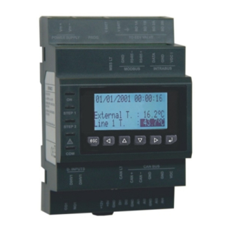
Page 8: Description
PSD04 | User manual ver. 3.6 | Code 144PSDI364 DESCRIPTION Description The following drawing shows the aspect of PSD04. The following table shows the meaning of the parts of PSD04. Part Meaning digital output analog inputs and free of voltage digital inputs... -
Page 9: Size And Installation
Parker RAC Europe PSD04 | User manual ver. 3.6 | Code 144PSDI364 SIZE AND INSTALLATION Size The following drawing shows the size of PSD04 (4 DIN modules); size in mm (in). Page 9 of 74... -
Page 10: Installation
Parker RAC Europe PSD04 | User manual ver. 3.6 | Code 144PSDI364 Installation On DIN rail 35.0 x 7.5 mm (1.377 x 0.295 in) or 35.0 x 15.0 mm (1.377 x 0.590 in). To install the device operate as shown in the following drawing. -
Page 11: Electrical Connection
Parker RAC Europe PSD04 | User manual ver. 3.6 | Code 144PSDI364 ELECTRICAL CONNECTION Meaning of the connectors The following drawing shows the connectors of PSD04. The following tables show the meaning of the connectors; for further information look at chapter 11 “TECHNICAL DATA”. - Page 12 Parker RAC Europe PSD04 | User manual ver. 3.6 | Code 144PSDI364 common analog inputs and free of voltage digital inputs analog input 1 (which can be set via configuration parameter for NTC/Pt 1000 probes and for 0-20 mA/4-20 mA/0-5 V ratiometric transducers)
- Page 13 SO 2A bipolar stepper motor coil 2 SO 2B bipolar stepper motor coil 2 With reference to the previous table, the following one shows how to connect to PSD04 the Sporlan range of EEV valves. Wire (color) Terminal Sporlan SER, SERI and SEHI...
- Page 14 Parker RAC Europe PSD04 | User manual ver. 3.6 | Code 144PSDI364 Power supply Terminal Meaning power supply device (not isolated; 24 VAC +10% -15%, 50/60 Hz ±3 Hz, 40 VA max. or V≅+ 24... 37 VDC, 22 W max.) power supply device (not isolated;...
-
Page 15: Example Of Electrical Connection
The following drawing shows an example of electrical connection of PSD04. Please note the power supply of PSD04 and that of PSS4B are not isolated one from the another: it is important to wire the devices correctly as indicated in the drawing. -
Page 16: Additional Information For Electrical Connection
11 “TECHNICAL DATA” disconnect the power supply of the device before servicing it do not use the device as safety device for the repairs and for information about the device please contact the Parker RAC Europe sales network. Page 16 of 74... -
Page 17: User Interface
USER INTERFACE Preliminary information PSD04 is available with built-in LCD display keyboard and blind version (according to the model). The built-in versions can be programmed through the keyboard interface, blind ones can be programmed by using a remote user interface (for example PSV4GBR if the version has a CANBus card fitted): both versions with display or without display can be programmed through the set-up software system Parameters Manager. - Page 18 Parker RAC Europe PSD04 | User manual ver. 3.6 | Code 144PSDI364 LED auxiliary if parameter Ph80 = 0, LED status if it is lit, the device will be working in superheating algorithm modality if it flashes slowly, the device will be working in manual or in debugger modality...
-
Page 19: Operation
Parker RAC Europe PSD04 | User manual ver. 3.6 | Code 144PSDI364 OPERATION Switch on and resynchronization At switch-on and after a resynchronization, the fundamental parameters for moving the motor are acquired. The parameters of pressure and temperature units of measure are loaded at switch-on, and, if necessary, is performed the conversion of all the parameters of pressure and temperature. - Page 20 The Driver type (parameter DrTy) used depends on the hardware, while the Stepper type (parameter StTy) depends on the motor to be controlled; currently, the PSD04 can only be used with Parker Sporlan bipolar stepper motors. The driving mode can be selected through parameter Driving mode selection (Pi01).
-
Page 21: Operating Mode
6.2.1 Preliminary information PSD04 implements a stepper motor control according to the state machine presented in the table here below (hereinafter the document will make reference to these status). The state in which the algorithm is in may be readable in the FSM status (Finite State Machine, parameter Stat). -
Page 22: Enabling Psd04
PSD04. Selecting a value from 6 to 9, it is possible to operate the PSD04 in standalone mode if a communications fault occurs, in this case the DI1 or DI2 inputs must be configured as enable (parameter Ph11 = 1 or Ph21 = 1). -
Page 23: Algorithm Start-Up
Parker RAC Europe PSD04 | User manual ver. 3.6 | Code 144PSDI364 The other three analog input are configured according to their respective Ai probe usage (parameter Pia). Algorithm start-up To enter algorithm mode, from the Stand-by off (10), set the Main control type (parameter Pcty) with a value greater or equal to 6, and enable the valve. -
Page 24: Debugging Mode
Parker RAC Europe PSD04 | User manual ver. 3.6 | Code 144PSDI364 Debugging mode The debugger feature is enabled when Pr02 = 2: the valve will move from a Debug minimum position (parameter Prd1) to a Debug maximum position (parameter Prd2) with the step rate defined by Debug step rate (parameter Prd0). - Page 25 Parker RAC Europe PSD04 | User manual ver. 3.6 | Code 144PSDI364 With the operation mode selected, the regulator uses the related SH set-point parameter. This is a fundamental parameter for the proper functioning of the control algorithm. A low set-point ensures a higher evaporator performance, lower temperatures, and minimum variations, but has the disadvantage that liquid may reach the compressor.
-
Page 26: Configuration
Parker RAC Europe PSD04 | User manual ver. 3.6 | Code 144PSDI364 CONFIGURATION Unit of measurements Units of measurement used in the internal algorithm are Celsius (ºC) and Kelvin (K) degrees in tenths for temperatures, and barG in hundreds for pressure. - Page 27 10/12 The first five pages are dedicated to the end user and permit display of major features of the PSD04, any alarm messages, or whether it is necessary to resynchronise or reset the machine after changing parameters. In the third page, the fourth line is visible and blinking only if there is a request for resynchronization;...
- Page 28 Parker RAC Europe PSD04 | User manual ver. 3.6 | Code 144PSDI364 Press and release button ENTER. Press and release button UP or button DOWN to modify the value. Press and release button ENTER to confirm the value. Press and release button ESC over and over again to go back to the previous pages.
- Page 29 Parker RAC Europe PSD04 | User manual ver. 3.6 | Code 144PSDI364 In the “Main control parameters” the user can change the control type (analog positioner or SH algorithm), the algorithm sample time, the algorithm parameters set to be used and the parameters for each set, valve start-up position, valve position in case of probe or communication error, valve stand-by position, etc.
- Page 30 Parker RAC Europe PSD04 | User manual ver. 3.6 | Code 144PSDI364 page 23 page 23 page 23 page 27 page 28 page 29/30/31/32 - - - - - - - page 23 page 23 page 33 page 34 page 35...
-
Page 31: Configuring A Blind Version
The backup and restore functionalities are active only in Stand-by off (10). They are protected by the Level 5 password and permit to download a copy of the PSD04 application's parameters and/or the driver's parameter (communication settings, etc.) in the memory or in the parameters key. -
Page 32: Configuring The Device Through The Programming Key Pskey10
Parker RAC Europe PSD04 | User manual ver. 3.6 | Code 144PSDI364 According to the factory setting the address of the CAN node of an electronic expansion valve driver has value 11 (therefore operate on the interface to set parameter NW Node to [ 1 ] 11). -
Page 33: Connecting The Device Through The Set-Up Software System Parameters Manager
Parker RAC Europe PSD04 | User manual ver. 3.6 | Code 144PSDI364 The copy of the parameters from the programming key PSKEY10 to the device is allowed on condition that the firmware of the devices coincides. To quit the procedure operate as follows: Press and release button ESC over and over again: possible modifications will not be saved. -
Page 34: Backup And Restore
Parker RAC Europe PSD04 | User manual ver. 3.6 | Code 144PSDI364 Press and release button UP or button DOWN to select the submenu. Press and release button ENTER. To gain access a protected submenu operate as follows: From step 2.1 or step 2.2, press and release button UP or button DOWN to select the submenu. -
Page 35: List Of Configuration Parameters
Parker RAC Europe PSD04 | User manual ver. 3.6 | Code 144PSDI364 List of configuration parameters The following is a complete list of parameters managed by the application, each with a short code, the ModBus address (Adr), brief description, default values and limits, measurement units (U), the menu in which they are accessed (M) and the notes. - Page 36 Parker RAC Europe PSD04 | User manual ver. 3.6 | Code 144PSDI364 Pc13 100.0 40.0 User PID proportional band Pc14 User PID integral time Pc15 User PID derivative time Pc20 Installer start-up delay Pc21 0.00 100.00 50.00 Installer start-up position Par.
- Page 37 Parker RAC Europe PSD04 | User manual ver. 3.6 | Code 144PSDI364 Pa02 Installer communication alarm delay enable LoSH alarm Pa10 - - - - Installer = yes Pa11 25.0 Installer LoSH alarm hysteresis Pa12 Installer LoSH alarm delay enable HiSH alarm...
- Page 38 Parker RAC Europe PSD04 | User manual ver. 3.6 | Code 144PSDI364 enable main power supply alarm Pa70 - - - - Installer = yes Pa71 Installer main power supply alarm delay enable backup battery alarm Pa75 - - - -...
- Page 39 Parker RAC Europe PSD04 | User manual ver. 3.6 | Code 144PSDI364 valve selection = Sporlan SER AA = Sporlan SER A = Sporlan SER B = Sporlan SER C = Sporlan SER D = Sporlan SERI F = Sporlan SERI G...
- Page 40 Parker RAC Europe PSD04 | User manual ver. 3.6 | Code 144PSDI364 resynchronization interval Pr41 Installer = disabled Pr45 Manufact. reserved Pr48 0.00 100.00 0.00 Installer communication error position Par. Min. Max. Units Default Menu Valve and driver: debug Prd0...
- Page 41 Parker RAC Europe PSD04 | User manual ver. 3.6 | Code 144PSDI364 free voltage digital input function = none Ph11 - - - - Manufact. = enable/disable valve = change parameters set = resynchronization request = backup battery status free of voltage digital input DI2 logic...
- Page 42 Parker RAC Europe PSD04 | User manual ver. 3.6 | Code 144PSDI364 analog input AI1 function = not used Piu1 - - - - Manufact. = suction temperature backup probe = suction pressure backup probe analog input AI1 probe type...
- Page 43 Parker RAC Europe PSD04 | User manual ver. 3.6 | Code 144PSDI364 Y type P1Tty - - - - Manufact. = barG = barA P1YM P1Ym 300.00 barG/barA 1.00 Manufact. Y max value P1Ym P1YM barG/barA 0.00 Manufact. Y min value 300.00...
- Page 44 Parker RAC Europe PSD04 | User manual ver. 3.6 | Code 144PSDI364 Probe settings: analog input AI2 Par. Min. Max. Units Default Menu scaling X type = 0-20 mA P2Xty - - - - Manufact. = 4-20 mA = 0-5 V 0:20.00...
- Page 45 Parker RAC Europe PSD04 | User manual ver. 3.6 | Code 144PSDI364 analog input AI4 probe type 10 = 4-20 mA transducer (0.5 - 8 barA) 11 = 4-20 mA transducer (0 - 30 barA) 12 = 4-20 mA transducer (-1 - 8...
- Page 46 Parker RAC Europe PSD04 | User manual ver. 3.6 | Code 144PSDI364 suction pressure (converted into OfsTe -10.0 10.0 User temperature) offset Par. Min. Max. Units Default Menu Communication settings Mb0a - - - - Manufact. MODBUS RS-485 port address...
- Page 47 Parker RAC Europe PSD04 | User manual ver. 3.6 | Code 144PSDI364 CAN baud rate = 10K = 20K CANb - - - - Manufact. = 50K = 125K = 500K Par. Min. Max. Units Default Menu Command functioning mode...
- Page 48 Parker RAC Europe PSD04 | User manual ver. 3.6 | Code 144PSDI364 FSM status = initialization = synchronization wait = positioning wait = probe alarm = grid alarm = communication alarm 10 = stand-by off Stat - - - -...
- Page 49 Parker RAC Europe PSD04 | User manual ver. 3.6 | Code 144PSDI364 configuration warning = correct configuration = incorrect configuration start-up = invalid value for parameter Pia1 = invalid value for parameter Pia2 = invalid value for parameter Pia3 = invalid value for parameter...
- Page 50 Parker RAC Europe PSD04 | User manual ver. 3.6 | Code 144PSDI364 enable valve status EnaS - - - - - - - - User = valve not enabled = valve enabled resynchronization request status ResS - - - -...
- Page 51 Parker RAC Europe PSD04 | User manual ver. 3.6 | Code 144PSDI364 Pe prymary probe 0: AI1 PePr - - - - - - - - - - - - - - - - User 0: AI2 0: AI3 0: AI4...
- Page 52 Parker RAC Europe PSD04 | User manual ver. 3.6 | Code 144PSDI364 Pnum - - - - - - - - - - - - - - - - User project number project variation = AA Pvar - - - -...
-
Page 53: Serial Communication
The controller sends information to the driver necessary for it to correctly control its functions, and the driver responds, communicating internal information, such as the pressure and temperature measurements, alarms, etc. The connection methods available on the PSD04 are CANBUS, MODBUS RS-485, and MODBUS on the setting and programming port, according to the model. - Page 54 Parker RAC Europe PSD04 | User manual ver. 3.6 | Code 144PSDI364 set 2: PID derivative time (Pp15) set 1: start-up delay (Pc20) set 2: start-up delay (Pp20) set 1: start-up position (Pc21) set 2: start-up position (Pp21) Fast action start threshold (FaTh)
-
Page 55: Modbus Serial Communication
Parker RAC Europe PSD04 | User manual ver. 3.6 | Code 144PSDE364 For the variables that need an immediate refresh, commands are implemented. The CommandOut allows to write commands on the device. The device performs the new values as soon as possible. -
Page 56: Alarms And Errors
Parker RAC Europe PSD04 | User manual ver. 3.6 | Code 144PSDE364 ALARMS AND ERRORS Alarms and errors The system supports a series of alarms related to both the system (memory, probes, communication, configuration, etc.), and the regulation algorithm (LoSH, HiSH, LOP, MOP, LowPressure). -
Page 57: Communication Error
Parker RAC Europe PSD04 | User manual ver. 3.6 | Code 144PSDE364 Invalid value for parameter PIA2 Invalid value for parameter PIA3 Invalid value for parameter PIA4 PIu1 configured as another Piux Parameters Piu1, Piu2, Piu3 and Piu4 must each PIu2 configured as another PIux have different values, or null. -
Page 58: Probe Error
Stand-by off. Power failure and backup battery error The PSD04 supports connection to a backup battery in order to allow a complete closure of the valve in the case of power supply failure. There are two alarms: one for the power supply failure (bit 8), the other for a malfunction of the backup battery (bit 9). -
Page 59: Algorithm Status
Parker RAC Europe PSD04 | User manual ver. 3.6 | Code 144PSDE364 Algorithm status Bit 10 of Alarm status (AlSt) is raised for LOP, MOP, LoSH, HiSH, LowPressure or if the measures needed by the algorithm are not valid. This monitoring is in effect only while the system is working in SH-algorithm and in manual mode. -
Page 60: Mop
Ph61. If this alarm occurs, the user should check and correct all the parameters of temperature and pressure, cancel the alarm leading to 1 bit 0 of the variable Command (Cmd), and then reset the PSD04. page 60 of 74... -
Page 61: Accessories
Parker RAC Europe PSD04 | User manual ver. 3.6 | Code 144PSDE364 ACCESSORIES 10.1 Programming key PSKEY10 10.1.1 Introduction PSKEY10 is a programming key. Through the key it is possible to make the upload and the download of the application software parameters and / or of the configuration ones. -
Page 62: Programming Kit Psif20Tuxi
Parker RAC Europe PSD04 | User manual ver. 3.6 | Code 144PSDE364 10.2 Programming kit PSIF20TUXI 10.2.1 Introduction PSIF20TUXI is a programming kit. Through the kit it is possible to connect the driver to the set-up software system Parameters Manager (using the programming port). -
Page 63: Size
Parker RAC Europe PSD04 | User manual ver. 3.6 | Code 144PSDE364 10.2.3 Size Size is in mm (in). 10.2.4 Connection to the Personal Computer Operate as follows: Plug in an end of the TTL cable into the TTL port of the serial interface. -
Page 64: Description
Parker RAC Europe PSD04 | User manual ver. 3.6 | Code 144PSDE364 10.3.2 Description The following drawing shows the aspect of the interface PSIF20SUXI. The following table shows the meaning of the parts of the kit. Part Meaning USB cable 2 m (6 ft) long RS-485 cable 2.5 m (8 ft) long... -
Page 65: Size
Parker RAC Europe PSD04 | User manual ver. 3.6 | Code 144PSDE364 10.3.3 Size Size is in mm (in). 10.3.4 Connection to the Personal Computer Operate as follows: Connect the RS-485 port on screw terminal block of the interface to the RS-485 port of the device using three... -
Page 66: Backup Module Pss4B
Parker RAC Europe PSD04 | User manual ver. 3.6 | Code 144PSDE364 10.4 Backup module PSS4B 10.4.1 Introduction PSS4B is a backup module. Through the module it is possible to close the valve in case of lack of power supply of the driver. -
Page 67: Size
Connection to the device Look at chapter 4 “ELECTRICAL CONNECTION”Operate as follows: Please note the power supply of PSD04 and that of PSS4B are not isolated: it is important to wire correctly the devices as indicated in chapter 4. page 67 of 74... -
Page 68: Technical Data
Parker RAC Europe PSD04 | User manual ver. 3.6 | Code 144PSDE364 TECHNICAL DATA 11.1 Technical data Purpose of the device: electronic expansion valves driver. Box: self-extinguishing grey. 71.0 x 128.0 x 60.0 mm (2.795 x 5.039 x 2.362 in; W x H x D);... - Page 69 Parker RAC Europe PSD04 | User manual ver. 3.6 | Code 144PSDE364 The maximum lengths of the connecting cables are the following: power supply device: 30 m (98 ft) analog inputs: 100 m (328 ft) power supply 0-20 mA/4-20 mA/0-5 V ratiometric/0-10 V...
- Page 70 Parker RAC Europe PSD04 | User manual ver. 3.6 | Code 144PSDE364 NTC analog inputs (10K Ω @ 25 °C, 77 °F) Kind of sensor: ß3435. Working range: from -40 to 110 °C (from -40 to 230 °F) for standard NTC probes from -50 to 150 °C (from -58 to...
- Page 71 Parker RAC Europe PSD04 | User manual ver. 3.6 | Code 144PSDE364 Power supply 0-20 mA/4-20 mA/0-10 V transducers: 12 VDC ±10%, 60 mA max. Power supply 0-5 V ratiometric transducers: 5 VDC ±5%, 40 mA max. The device incorporate a restorable thermal protection of the power supplies against the short circuit and the overload.
- Page 72 Parker RAC Europe PSD04 | User manual ver. 3.6 | Code 144PSDE364 Electromechanical relay Maximum switching power: 1,250 VA (150 W). Mechanical life: > to 5,000,000 operations. Electrical life: > to 100,000 operations. Protection: none. The device ensure a reinforced isolation among each terminal of the digital output and the remaining parts of the device.
- Page 73 Parker or its subsidiaries or authorized distributors. To the extent that Parker or its subsidiaries or authorized distributors provide component or system options based upon data or specifications provided by the user, the user is responsible for determining that such data and specifications are suitable and sufficient for all applications and reasonably foreseeable uses of the components or systems.
- Page 74 Parker RAC Europe PSD04 | User manual ver. 3.6 | Code 144PSDE364 Parker Hannifin Ltd - RAC Europe Brampton S73 OUF phone +44 (0) 1226 273400 fax +44 (0) 1226 273401 page 74 of 74...
Need help?
Do you have a question about the PSD04 and is the answer not in the manual?
Questions and answers