Table of Contents
Advertisement
Quick Links
Advertisement
Table of Contents

Subscribe to Our Youtube Channel
Related Manuals for IDEAL 61-920


Summary of Contents for IDEAL 61-920
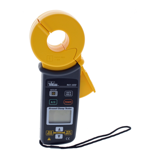
- Page 1 61-920 Ground Clamp Resistance Meter Instruction Manual...
-
Page 2: Table Of Contents
Contents 1. Safety Warnings This instrument has been designed, manufactured and tested according to IEC61010 1. Safety warnings ..................1 Safety Requirements for electronic measuring apparatus, and calibrated in accordance with 2. Features....................3 practices using equipment that is calibrated to standards traceable to the National Institute for Standards and Technology (NIST). -
Page 3: Features
2. Features DANGER The 61-920 is a digital clamp-on ground resistance tester. The instrument can measure • Do not use the instrument on a circuit where electrical potential exceeds 300VAC. the ground resistance by simply clamping around the ground conductor, ground rod or •... -
Page 4: Specifications
3. Specifications • Applicable standards IEC61010-1: 2001 (CAT. IV 300V Pollution degree 2) IEC61010-2-032: 2002 IEC61326: 2000 (EMC standard) • Electrostatic discharge Performance criteria B Measuring Function Range Resolution Accuracy immunity range • Withstand voltage AC5320Vrms/ 5 seconds 20Ω 0.01Ω 0.00 ~ 20.99Ω... -
Page 5: Instrument Layout
4. Instrument Layout 5. Measurement Theory • Feature callouts This instrument can measure the earth resistance to earth in a multi-earthed system. Let’s Transformer jaw regard earth resistance under test as Rx, and the other earth resistances as R1, R2, …Rn. Lever Backlight button Switches on/off the backlight... -
Page 6: Preparation For Measurement
6. Preparation for Measurement By applying the Voltage (V) to the circuit from the transformer jaw (CT1), current I is flowing in relation to the earth resistance. R can be determined by calculation after measuring the current with the other transformer jaw (CT2). In this case, R displayed in this meter can be CAUTION regarded as Rx because Rs can be regarded small enough against Rx. -
Page 7: Normal Measurement Of Current
7. Measuring Method 7.1 Normal Measurement of current • Press the Function button and select the ACA function. • Confirm the displayed unit is “ mA”, and the “ MEM” mark is not displayed at the upper left DANGER corner of the LCD. •... - Page 8 7.3 Measurement of earth resistance Earth resistance measurement of a pole grounding electrode. CAUTION • Follow the procedure described in “7-1 Normal measurement of current” and measure the current flowing on the earthed wire prior to the measurement of earth resistance. If “ “...
-
Page 9: Continuity Buzzer Function
8. Other Functions 8.5 Memory function This function saves and displays several measurement results. 8.1 Auto power-off function • Saving the measurement results This is a function to conserve battery power when the instrument is accidentally left on. The meter (1) Any data number (between 1 and 100) can be selected with the cursor button automatically turns off 10 minutes after the last button operation. -
Page 10: Battery Replacement
9. Battery replacement 10. Service If the instrument should fail to operate correctly, please go to the link below to fill out a service request: http://www.idlim.net/support/testerRMA.action WARNING • In order to avoid possible shock hazard, remove the meter from the conductor under test, For repair, the calibration plate used for proper operation check must be returned with the meter. -
Page 11: Warranty
This warranty constitutes the sole and exclusive remedy of the purchaser and the exclusive liability of IDEAL, and is in lieu of any and all other warranties, and expressly disclaims all other warranties, implied, or statutory as to merchantability, fitness for purpose sold, description, quality productiveness, or any other matter.
Need help?
Do you have a question about the 61-920 and is the answer not in the manual?
Questions and answers