Table of Contents
Advertisement
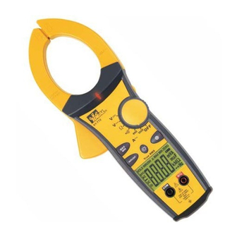
IDEAL INDUSTRIES, INC.
TECHNICAL MANUAL
MODELS:
61-764
61-766
61-768
The Service Information provides the following information:
•
Precautions and safety information
•
Specifications
•
Performance test procedure
•
Calibration and calibration adjustment procedure
•
Basic maintenance (replacing the battery)
Form number: TM61764-6-8
Revision: 5. Date: Nov 2007
Form number TM61764-6-8
Rev 5 November 2007
Advertisement
Table of Contents

Related Manuals for IDEAL 61-764


Summary of Contents for IDEAL 61-764
- Page 1 IDEAL INDUSTRIES, INC. TECHNICAL MANUAL MODELS: 61-764 61-766 61-768 The Service Information provides the following information: • Precautions and safety information • Specifications • Performance test procedure • Calibration and calibration adjustment procedure • Basic maintenance (replacing the battery) Form number: TM61764-6-8 Revision: 5.
-
Page 2: Table Of Contents
TABLE OF CONTENTS Page Title Introduction Precautions and Safety Information Symbol Table TightSight™ Display Notes High Voltage Warning (HI-V) Safety Information Certifications and Compliance Specifications General Specification Voltage Specifications Current Specifications Resistance Specifications Frequency Specification Capacitance Specifications Continuity Specifications Performance Verification Calibration Calibration Reference Points 9/10... -
Page 3: Introduction
The 61-760 series contains parts that can be damaged by static discharge. Follow the standard practices for handling static sensitive devices. For additional information about IDEAL INDUSTRIES, INC. and its products, and services, visit IDEAL INDUSTRIES, INC. web site at: www.idealindustries.com Precautions and Safety Information Use the meter only as described in the Users Manual. -
Page 4: High Voltage Warning (Hi-V)
Page 2 High Voltage Warning (HI-V): The meter beeps and lights an LED when >30V AC/DC voltage is present through test leads of the meter. This enhanced safety feature alerts the user that dangerous voltage is present across the leads even if the meter is set on an incorrect function or range. Notes: This feature does not work through the clamp head as the clamp is intended to only measure current. -
Page 5: Certifications And Compliance
-20°C to 60°C (-4°F to 140°F) at <80% relative humidity Power source: 9V Battery (NEDA 1604) Battery Life: 200 hours typical (alkaline) {61-764} 200 hours typical (alkaline) {61-766} 150 hours typical (alkaline) {61-768} Low Battery Indicator: symbol indicates low battery voltage... -
Page 6: Voltage Specifications
Page 4 61-764 Function / Ranges Accuracy Range 660.0mV, 50Hz - 60Hz 1.7% + 8digits 6.600V/66.00V/660.0V, 50Hz - 100Hz 1.2% + 8 digits AC Voltage 6.600V/66.00V/660.0V, 100Hz - 400Hz 1.5% + 8 digits 750V, 50Hz - 400Hz 1.5% + 8 digits 660.0mV... -
Page 7: Performance Verification
Page 5 AC Converter: 61-764 - Average responding, RMS Calibrated to Sine Wave 61-766, 61-768 – True RMS sensing Overload Protection: AC and DC Voltage: Not to exceed 1000V DC or 750VAC RMS AC Current: Not to exceed 660A AC... - Page 8 510.5 61-768 Table 5 Resistance Test High Function /Range Input Model Number Limit Limit Ω 660 98.6 101.4 61-764, 61-766, 61-768 100Ω Ω 6.6K .986 1.014 61-764, 61-766, 61-768 1KΩ Ω 66K 9.86 10.14 61-764, 61-766, 61-768 10KΩ Ω 400K 98.6...
-
Page 9: Calibration
V DC Calibration: 61-764 (Refer to Figure 1A), 61-766 (Refer to Figure 2A), 61-768 (Refer to Figure 3A) Set the function / range to 6.6V DC. Connect the calibrator to the V and COM inputs on the meter. - Page 10 Calibration Procedure (cont’d) A AC Calibration: 61-764 (Refer to Figure 1B), 61-766 (Refer to Figure 2B) (Adjustments made under front panel label.) Set the function / range to the 660A AC. Set output of the AC calibrator for 10.00A/60Hz +/- 0.01% and connect it to Coil = 10N = 100.0A Clamp the jaws to the coil = 10N.
-
Page 11: Calibration Reference Points
Page 9 61-764 (Figure 1A) 61-764 (Figure 1B) 61- 766 (Figure 2A) 61-766 (Figure 2B) Form number TM61764-6-8 Rev 5 November 2007... - Page 12 Page 10 61-768 (Figure 3A) 61-768 (Figure 3B) Form number TM61764-6-8 Rev 5 November 2007...
-
Page 13: Replacing The Battery
Page 11 Battery Replacement (Refer to Figure 4) 1. Disconnect the test leads from any circuit under test and turn off meter. 2. Use a Philips head screwdriver to remove the screws on battery cover. 3. Remove battery from the battery compartment. 4.
Need help?
Do you have a question about the 61-764 and is the answer not in the manual?
Questions and answers