Table of Contents
Advertisement
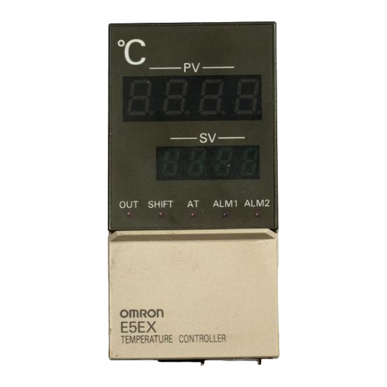
DIN-sized (96 x 48-mm) Temperature
Controller Featuring Advanced PID
Control and Heater Burnout Detection
Advanced Pid Control with two degrees of freedom
improves stability and response speed.
Heater burnout alarm built in.
Select from seven temperature sensors and a total
of 14 temperature ranges (seven Fahrenheit and
seven Celsius).
High accuracy: 0.3% of set value.
Ordering Information
The model numbers for the basic Temperature Controller, its five Control Output Units, and two Current Transformers are given below. Be sure
to specify an Control Output Unit and Current Transformer when ordering.
Example: E5EX–AH, Relay Output Unit E53–R, Current Transformer E54–CT1
Models set to display in degrees Fahrenheit (°F) can be ordered by adding "–F" to the end of the model number. Example: E5EX–AH–F
The scale indication switch will then be set to °F prior to shipment from the factory.
Temperature Controllers
Model
E5EX–AH
Control Output Units
Output
Relay output
Model
E53–R
Hole diameter
5.8 mm
Model
E54–CT1
Temperature Ranges
Input (switch
selectable)
K (CA)
Chromel vs.
alumel
°C
Range
–200 to 1,300
°F
–300 to 2,300
Resolution (°C/°F)
1
(main settings and
alarm)
SSR output
Voltage output (for driving SSR)
12 VDC, NPN
E53–S
E53–Q
12.0 mm
E54–CT3
J/L (IC)
T/U (CC)
Iron vs.
Copper vs.
constantan
constantan
–100 to 850
–200 to 400
–100 to 1,500
–300 to 700
24 VDC, NPN
24 VDC, PNP
E53–Q3
E53–Q4
Thermocouple
E (CRC)
R (PR)
Chromel
Platinum vs.
vs.
platinum
constantan
rhodium 13%
0 to 600
0 to 1,700
0 to 1,100
0 to 3,000
E5EX–H
Temperature
resistance
thermometer
S
PT platinum
Platinum vs.
resistance
platinum
thermometer
rhodium 10%
(Pt100/JPt100)
0 to 1,700
–99.9 to 450.0
0 to 3,000
–99.9 to 800.0
0.1
1
Advertisement
Table of Contents

Related Manuals for Omron E5EX–H


Summary of Contents for Omron E5EX–H
-
Page 1: Ordering Information
E5EX–H TEMPERATURE CONTROLLER DIN-sized (96 x 48-mm) Temperature Controller Featuring Advanced PID Control and Heater Burnout Detection Advanced PID control with two degrees of freedom improves stability and response speed. Heater burnout alarm built in. Select from seven temperature sensors and a total of 14 temperature ranges (seven Fahrenheit and seven Celsius). -
Page 2: Specifications
E5EX–H E5EX–H Specifications Temperature Controller Ratings Supply voltage 100 to 240 VAC, 50/60 Hz Operating voltage range 85% to 110% of rated supply voltage Power consumption Approx. 10 VA (at 100 VAC) to 15 VA (at 240 VAC) Input Thermocouple (K/J/T/E/R/S/L/U) or temperature resistance thermometer (Pt100/JPt100) selectable Current Transformer input See Current Transformer Ratings. - Page 3 E5EX–H E5EX–H Temperature Controller Characteristics +0.3% of set value or ±1°C, whichever ±1 digit max. Setting accuracy* Set value coincides with the indicated value, because no relative error exists between both values. Indication accuracy 0.0° to 999.9 °C/°F (in units of 0.1°) Hysteresis (during ON/OFF control action) 0.0°...
- Page 4 E5EX–H E5EX–H Dimensions Note: All units are in millimeters. Temperature Controller Panel Cutout Side-by-side Mount- ing of N Controllers 120 min. Mounting screw Current Transformer E54–CT1 E54–CT3 2.36 dia 2.8 dia dia. dia. Two, 3.5 dia. holes Nomenclature Auto-tuning Indicator Process Value (PV) Display Flashes on and off about every Displays not only the process temperature but also indi-...
- Page 5 E5EX–H E5EX–H Operation NOTICE: Always turn off the power supply to the Temperature Controller before changing any switch settings. Accessing Switches and Selectors Before supplying power to the Temperature Controller, the selectors and switches shown below must be set to specify the temperature sensor, functions, and alarm mode.
- Page 6 E5EX–H E5EX–H Temperature Sensor Selector (SW206, Function Control setting INPUT) number setting This selector determines the temperature sensor to be used. It is set Operating mode ON/OFF operation to position 2 before shipment to designate a K-type (chromel-alumel PID operation* thermocouple) temperature sensor.
- Page 7 E5EX–H E5EX–H Alarm Mode Selector (SW205: ALM) An alarm mode selector is provided. Ten alarm modes, listed in the following table, can be selected using this switch. The switch is set to position 2 before shipment, i.e., the upper-limit alarm mode. Switch Mode (SW205) Alarm output...
- Page 8 E5EX–H E5EX–H Standby Sequence Alarm functions with standby sequence suppress nuisance alarms when the controller is first powered up. As shown in the temperature charts at right, the alarm output is suppressed until the temperature exceeds the alarm band or alarm limit one time. Protection Switch (SW101, PROTECT) When the protection switch is set to the ON position, the level key, up and down keys, and auto-tuning key will not operated.
- Page 9 E5EX–H E5EX–H Alarm: al Power up (temperature setting) When al is displayed on the PV display, the alarm value for alarm Process temperature output can be set on the SV display. When the temperature exceeds Press a. or falls below the set alarm value, the corresponding alarm output is produced and the ALM indicator on the front panel lights.
- Page 10 E5EX–H E5EX–H Heater Burnout Alarm: ct, hb Level 1 Set a burnout current value to determine disconnections of the heat- In this level, the upper- and lower-limit values of the temperature range, control period, hysteresis, heater current, and heater burn- er.
- Page 11 E5EX–H E5EX–H Connected to Temperature Controller 2. ON/OFF Control When pin 1 on the operating mode selector (SW201) is set to the ON position, the temperature setting range limit values, hysteresis, heater current, and heater burnout alarm value can be set or changed.
- Page 12 E5EX–H E5EX–H Level 2 Display Alarm mode In level 2 the control output variable, temperature sensor, and No display No alarm modes for alarm output can be monitored. Note that level 2 is a mon- itoring level only and thus no parameter can be changed. When the )--( Upper- lower-limit...
- Page 13 E5EX–H E5EX–H Beginning Control Operation Temperature control is begun for the set values as soon as the pow- second or more. Automatic tuning can be executed at any time: on er is turned on, and temperature control is carried out according to power up, while the temperature is rising, and after the control ac- the parameters that have been input.
-
Page 14: Error Messages
E5EX–H E5EX–H Error Messages The Temperature Controller is provided with self-diagnostic functions, and will display the following error messages on the PV display in case of an error. Message Cause Control output Alarm output ffff Input temperature has risen beyond the upper limit of OFF during reverse Sends alarm signal in accor- the temperature range by more than 20°C... - Page 15 E5EX–H E5EX–H Precautions Mounting short-circuit bar shown in the terminal block diagram on the hous- ing. Use lead wires having a small resistance for temperature resis- The dimensions of the Temperature Controller conform to DIN tance thermometers. 43700. Recommended panel thickness is 1 to 8 mm. Be sure to remove the short-circuit bar from the terminals when a Do not install the Temperature Controller in a location exposed to temperature resistance thermometer is used.
- Page 16 To convert millimeters into inches, multiply by 0.03937. To convert grams into ounces, multiply by 0.03527. Cat. No. H49–E1–1 In the interest of product improvement, specifications are subject to change without notice. OMRON Corporation Temperature Control Devices Division 9th Fl., Osaka Center Bldg.
Need help?
Do you have a question about the E5EX–H and is the answer not in the manual?
Questions and answers