Advertisement
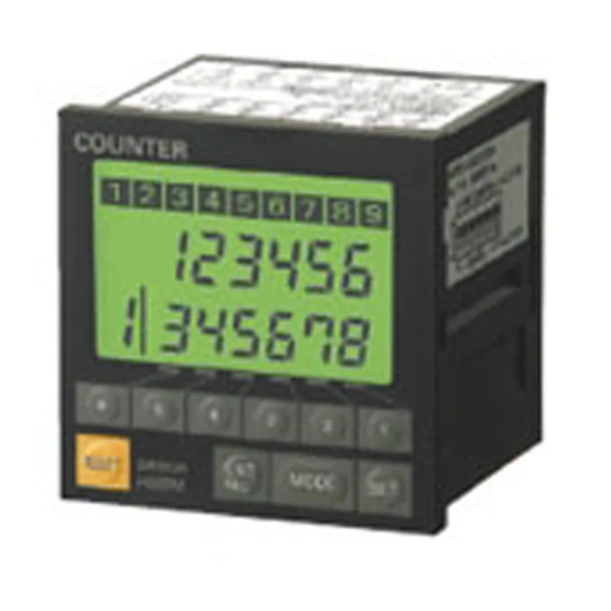
Multi-maintenance Counter
Nine Built-in Counters/Timers to
Measure Equipment Utilization
Up to nine Counters can be used as counters or
accumulative timers.
Can be used as a multi-stage preset counter.
Individual outputs to indicate maintenance timing.
Pre-forecast/Forecast and machine stoppage
output provided.
IP54F enclosure rating for resistance to oil and
water.
Compact, short-body: 72 x 72 x 79 mm (DIN).
Directly connectable to 2-wire DC sensors.
Ordering Information
Number of stages
3-stage setting
3 s age se
g
1-stage setting
s age se
g
Accessories (Order Separately)
Replacement Parts
Name
Hard Protective Cover
Rubber Packing
A Hard Protective Cover and Rubber Packing are supplied with the
Counter.
NPN
PNP
NPN
PNP
Model
Y92A-72C
Y92S-25
Output
H8BM-B
H8BM-BP
H8BM-BD
H8BD-BDP
Short Bar
Short Bar
When the Counter is used as a multi-stage preset counter, wiring
will be facilitated if Counter inputs 1 through 9 are short-circuited
with the following Short Bar.
5-pole
4-pole
Both the 5-pole and 4-pole Short Bars are used to short-circuit the 9
Counter inputs.
H8BM
RC
Model
Y92S-26
1
Advertisement
Table of Contents

Related Manuals for Omron H8BM Series


Summary of Contents for Omron H8BM Series
- Page 1 Multi-maintenance Counter H8BM Nine Built-in Counters/Timers to Measure Equipment Utilization Up to nine Counters can be used as counters or accumulative timers. Can be used as a multi-stage preset counter. Individual outputs to indicate maintenance timing. Pre-forecast/Forecast and machine stoppage output provided.
-
Page 2: Specifications
H8BM H8BM Specifications Item H8BM-B, H8BM-BP H8BM-BD, H8BM-BDP Classification 3-stage setting 1-stage setting Mounting method Flush mounting External connections Screw terminals Enclosure ratings IP54F (panel surface) Display mode Up display Output mode F mode Reset system External, manual resets Timing function Input signal method Voltage inputs: High and low signal voltages (count, reset, re-monitor, counter select, I/O inhibit) Control output... -
Page 3: Block Diagram
H8BM H8BM Characteristics Insulation resistance 100 MΩ min. (at 250 VDC) (between current-carrying terminals and exposed non-current-carrying metal parts) Dielectric strength 1,000 VAC, 50/60 Hz for 1 min (between current-carrying terminals and exposed non-current-carrying metal parts) Impulse withstand voltage 1 kV (between power terminals) 1.5 kV (between current-carrying terminals and exposed non-current-carrying metal parts) Noise immunity 1 kV (between power terminals) and 600 V (between input terminals), square-wave noise via noise... - Page 4 H8BM H8BM Outputs Forecast (1 to 9) Each of these outputs turns ON when its forecast value has been reached. When Counter is used as totalizing counter, output one-shot signals as carry signals. Retain outputs until count values are reset. Turns ON when Counter is operating normally.
-
Page 5: Operation
H8BM H8BM Operation Operation 1. Selecting Counter/Timer Operation Note: 1. The modes marked * are not provided on the 1-stage type Counter. Whether each Counter operates as a counter or a timer can be spe- 2. I/O operations are always performed regardless of the cified on a DIP switch provided on the side panel of the Counter. - Page 6 H8BM H8BM 4. Press the SET Key to determine the set value. If o Key is 5. Re-monitoring Count Value pressed within 5 seconds after the SET Key has been A count value that has been reset by mistake can e recovered. (ex. pressed, the RUN mode is automatically restored.
-
Page 7: Output Indicator
H8BM H8BM 7. Count Value Display 9. Clearing Settings While the count input is ON, the period on the count value display The count values of all the Counters can be cleared by flashes. The timer operation measures time by totaling the ON time simultaneously holding down the RESET Key and COUNTER of the count input. -
Page 8: Timing Charts
H8BM H8BM Timing Charts Timer (3-stage Preset Operation) Counter (3-stage Preset Operation) Reset input Reset input Count input Count input 999999 99999.9 hr Machine stoppage value Machine stoppage value Forecast value Forecast value Pre-forecast value Pre-forecast value 0.0 hr Pre-forecast indicator Pre-forecast indicator Forecast output Forecast output... -
Page 9: Installation
H8BM H8BM Installation Mounting To mount the Counter, attach the two fixtures supplied as accesso- Provide enough space around the Counter when mounting it to en- ries to the left and right sides of the Counter, and securely tighten the sure a proper working space. - Page 10 H8BM H8BM Connections NPN Output Forecast output 1 Count input 1 Load Forecast output 2 Count input 2 DISPLAY Load Forecast output 3 Count input 3 Count value Load Setting value Forecast output 4 Count input 4 Count up Load Forecast output 5 Count input 5 Load...
-
Page 11: Input Circuits
H8BM H8BM PNP Output Count input 1 OUTPUT COM Count input 2 DISPLAY Forecast output 1 Count input 3 Count value Load Setting value Forecast output 2 Count input 4 Count up Load Forecast output 3 Count input 5 Load Forecast output 4 Count input 6 Load... - Page 12 Two-wire sensor H8BM 2. Low-level: transistor OFF Leakage current: 1.5 mA max. All inputs 3. Power voltage range: 20.4 to 30 VDC Use of the OMRON TL-XD or E2E-XD-N Sensors is recommended. IN COM 24 VDC Two-wire sensor H8BM 24 VDC...
-
Page 13: Power Supply
To convert millimeters into inches, multiply by 0.03937. To convert grams into ounces, multiply by 0.03527. Cat. No. M042-E1-1D In the interest of product improvement, specifications are subject to change without notice. OMRON Corporation Industrial Automation Company Measuring and Supervisory Controls Department...
Need help?
Do you have a question about the H8BM Series and is the answer not in the manual?
Questions and answers