Table of Contents
Advertisement
Quick Links
Advertisement
Table of Contents

Related Manuals for NGX Technologies BlueBoard Base


Summary of Contents for NGX Technologies BlueBoard Base
- Page 1 UM-BlueBoard Base BlueBoard Base USER MANUAL Page | 1...
-
Page 2: Table Of Contents
Audio jack ............................. 9 PS/2 keyboard ..........................9 LCD display ..........................10 Programming BlueBoard Base ......................10 Programming BlueBoard Base Through ISP ................... 10 Appendix ............................11 Functional Overview ........................11 USB Virtual COM Port Installation For Windows XP ..............12 Sample Programs ........................... -
Page 3: Introduction
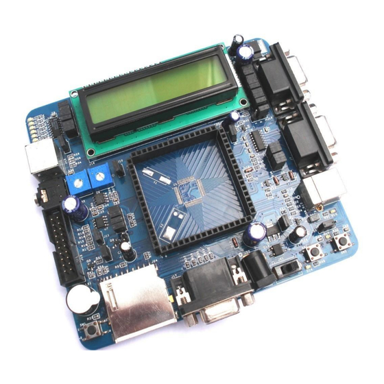
Stamp board(microcontroller) used. Ex: Using LPC2148 Stamp board all the features mentioned here are available. But if LPC1114 Stamp Board is used some features like USB, VGA, etc., are may not be available. This document is for the Blueboard Base + LPC2148 stamp. Hardware •... -
Page 4: Software
UM-BlueBoard Base Software • Firmware for USB bootloader • Preloaded program to test the peripherals Getting started Before you start working with the board you need to have a few things available. Requirement The requirements are divided in two sections. -
Page 5: Software
HyperTerminal / minicom) Validating BlueBoard Base Once you have all these accessories connected to the BlueBoard Base you can run a simple test to verify the proper working of all the peripherals. It is highly recommended that you test all the peripherals as soon you receive the BlueBoard. -
Page 6: Leds And Spi0
UM-BlueBoard Base LEDs and SPI0 Test setup: Connect jumpers to all pins of J9 to enable the LED's. A few seconds after the Blueboard is turned ON or reset; the LEDs will turn ON in ascending pattern and will turn OFF in descending order and this pattern will repeat three times. Please note that all the LEDs should glow;... - Page 7 UM-BlueBoard Base A “COM1 Properties” window appears. Set the values as shown below. Click OK. Next an empty “BlueBoard-Hyper Terminal” window opens as shown. Now make sure that the BlueBoard is powered and the serial port is connected to the respective port to be tested (UART0 or UART1).
-
Page 8: Usb
UM-BlueBoard Base For UART0: UART0 can also be used for serial programming. If the selected bootloader mode is Manual then Half modem cable should be used, else if it is in Auto mode use full modem cable. Note that after programming in auto mode the serial cable should be disconnected. -
Page 9: Vga Connector
UM-BlueBoard Base VGA connector Test setup: Connect the VGA connector on board (J17) to the computer monitor. A default image will appear. This confirms the working of VGA interface. Please note that to test the VGA interface the user has to power cycle the BlueBoard or reset it. The VGA is active only for few seconds. -
Page 10: Lcd Display
Magic utility. For programming with JTAG your system should have a parallel port or you can use the USB to JTAG from NGX Technologies and the supporting IDE which can communicate to the processor core over JTAG interface. We have successfully tested BlueBoard with wiggler clone JTAG and USB JTAG with CrossWorks IDE. -
Page 11: Appendix
The controller enters the bootloader mode if during reset the SW2 pin is low Appendix Functional Overview BlueBoard Base Utilitties For the working with BlueBoard Base there are certain tools that need to be installed. The tools required are: Flash Magic Tool. flash... -
Page 12: Usb Virtual Com Port Installation For Windows Xp
UM-BlueBoard Base http://www.hjtag.com/ For LINUX machines you may use http://www.pjrc.com/arm/lpc2k_pgm/ Tool chain: To be able to generate the hex or the binary file the user needs to install the tool chain for ARM based microcontrollers. Any toolchain can be used as long as it is able to generate the necessary files for downloading onto the BlueBoard. - Page 13 UM-BlueBoard Base Note: If the wizard does not open up automatically then the user needs to go the ‘Device Manager’ window and right click on the device and select ‘update driver’ Set the new hardware Wizard to search a specific location for the driver, and specify the folder containing usbser.inf...
-
Page 14: Sample Programs
• Buzzer- Code to demonstrate buzzer on external interrupt Known Issues While using the Auto-program mode for ISP; after programming the BlueBoard Base, user needs to unplug the full modem serial cable for the program to execute. --- Page | 14... -
Page 15: Legal
This evaluation board/kit is intended for use for ENGINEERING DEVELOPMENT, DEMONSTRATION, EDUCATION OR EVALUATION PURPOSES ONLY and is not considered by NGX Technologies Pvt. Ltd to be a finished end-product fit for general consumer use. Persons handling the product(s) must have electronics training and observe good engineering practice standards. As such, the goods...
Need help?
Do you have a question about the BlueBoard Base and is the answer not in the manual?
Questions and answers