Table of Contents
Advertisement
Quick Links
Advertisement
Table of Contents

Related Manuals for NGX Technologies BlueBoard-LPC214X


Summary of Contents for NGX Technologies BlueBoard-LPC214X
- Page 1 User Manual: BlueBoard-LPC214X USER MANUAL BlueBoard-LPC214X Revision 1.3...
- Page 2 The user assumes all responsibility and liability for proper and safe handling of the goods. Further, the user indemnifies NGX Technologies from all claims arising from the handling or use of the goods. Due to the open construction of the product, it is the user’s responsibility to take any and all appropriate precautions with regard to electrostatic discharge.
- Page 3 User Manual: BlueBoard-LPC214X Change Log: Revision 1 to Revision 1.1: Changed the product image • Added a note in section 3.2.8 for the SD/MMC connector regarding the card file format • Updated the ‘USB Virtual COM Port Installation for Windows XP’ section •...
-
Page 4: Table Of Contents
User Manual: BlueBoard-LPC214X Table of Contents INTRODUCTION ......................5 ....................... 5 OARD EATURES GET GOING........................6 ......................6 YSTEM EQUIREMENTS ........................6 TARTING OFF 2.2.1 Connecting the hardware ............... 6 2.2.2 Programming BlueBoard ................ 6 BLUEBOARD HARDWARE ....................8 ......................8 UNCTIONAL VERVIEW ....................9... -
Page 5: Introduction
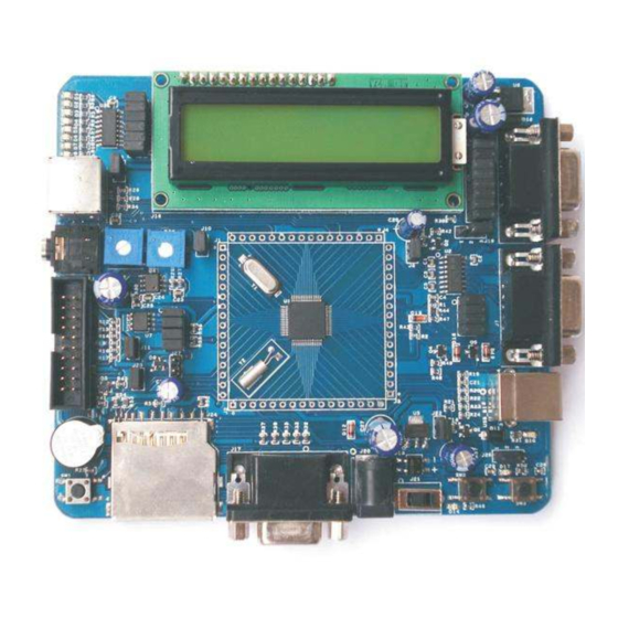
User Manual: BlueBoard-LPC214X 1 INTRODUCTION 1.1 BlueBoard Features BlueBoard-LPC214X is a evaluation board for LPC2148 ARM7TMDI based microcontroller. The LPC2148 microcontroller has 512KB of internal flash and 32+8K RAM. Following are the salient features of the board. Dimensions: 114 X 127 mm2... -
Page 6: Get Going
User Manual: BlueBoard-LPC214X 2 Get going 2.1 System Requirements Windows XP Serial or Parallel port USB port 2.2 Starting off 2.2.1 Connecting the hardware After unpacking the BlueBoard connect a DC supply of 7.5V/800mA to the DC jack to power the board. - Page 7 User Manual: BlueBoard-LPC214X displayed on LCD. Open Flash Magic tool, select the appropriate COM port, set the Baud rate to less than or equal to 38400 bps, select device as LPC2148, interface as 'None (ISP)' and oscillator frequency as 12MHz. Specify the path of your HEX file and click START. The status is shown at the bottom on the Flash Magic window.
-
Page 8: Blueboard Hardware
User Manual: BlueBoard-LPC214X 3 BlueBoard Hardware 3.1 Functional Overview 2x16 CHARACTERS LCD DISPAY PS/2 KEYBOARD 74HC595 LPC214x AUDIO AUDIO DB9 Female AMPLIFIER JACK Connector for UART1 SD/MMC Connector DB9 Female Connector for UART0 BUZZER USER USB Type B BUTTON connector... -
Page 9: Hardware Configurations
User Manual: BlueBoard-LPC214X 3.2 Hardware Configurations Modules and Jumpers Relationship Jumper Related Module Usage UART0 &UART1 Connecting all pins enables both UART0 and UART1.Pins 1 and 3 enable UART and pins 5 and 7 enable UART0. VREF voltage Connecting this will set the VREF voltage to 3.3V. - Page 10 User Manual: BlueBoard-LPC214X 3.2.1 LEDs and SPI0 Test setup: Connect jumpers to all pins of J9 to enable the LED's. A few seconds after the Blueboard is turned ON or reset; the LEDs will turn ON in ascending pattern and will turn OFF in descending order and this pattern will repeat three times.
- Page 11 User Manual: BlueBoard-LPC214X A “Connect To” window opens where you have to select the COM port. In this example it is COM1.Click OK. A “COM1Properties” window appears.Set the values as shown below.Click OK. Revision 1.3...
- Page 12 User Manual: BlueBoard-LPC214X Next an empty “BlueBoard-Hyper Terminal” window opens as shown. Revision 1.3...
- Page 13 User Manual: BlueBoard-LPC214X Now make sure that the BlueBoard is powered and the serial port is connected to the respective port to be tested (UART0 or UART1). By pressing any key from keyboard the following message will appear for the respective UART.
- Page 14 User Manual: BlueBoard-LPC214X For UART0: UART0 can also be used for serial programming. If the selected bootloader mode is Manual then Half modem cable should be used, else if it is in Auto mode use full modem cable. Note that after programming in auto mode the serial cable should be disconnected.
- Page 15 User Manual: BlueBoard-LPC214X For UART1: 3.2.3 USB USB Virtual COM Port Installation for Windows XP Before moving ahead with this section, refer to section. Test setup: Connect the USB cable to USB connector. The power LED (D14) and USB connect LED (D10) turn ON.
- Page 16 User Manual: BlueBoard-LPC214X 3.2.4 VGA connector Test setup: Connect the VGA connector on board (J17) to the computer monitor. A default image will appear. This confirms the working of VGA interface. Please note that to test the VGA interface the user has to power cycle the BlueBoard or reset it.
- Page 17 3.2.11 LCD display Test setup: To enable the LCD connect jumpers to all pins of J18. A default message “NGX TECHNOLOGIES” will be displayed and later status of SD/MMC and I2C is displayed. The back light of LCD can be controlled by connecting jumper to appropriate pins of J19.
-
Page 18: Blueboard Utilities
User Manual: BlueBoard-LPC214X 4 BlueBoard Utilities 4.1 Overview For the working with BlueBoard there are certain tools that need to be installed. The tools required to work with BlueBoard are: Flash Magic. The flash magic tool can be downloaded from the following link: http://www.flashmagictool.com/... -
Page 19: Troubleshooting
User Manual: BlueBoard-LPC214X 5 Troubleshooting 5.1 USB Virtual COM Port Installation For Windows XP The USB in BlueBoard might not get enumerated if it does not find the appropriate driver for it. To check USB enumeration status Right Click on “My Computer” icon and select Manage. A “Computer Management”... - Page 20 User Manual: BlueBoard-LPC214X Next, download the usbser.inf file from http://blueboard-lpc214x.googlecode.com/files/usbser.inf Place it in any convenient folder Plug in the device A Hardware Update Wizard opens up. Select the second option as shown and Click Next. Note: If the wizard does not open up automatically then the user needs to go the ‘Device Manager’...
- Page 21 User Manual: BlueBoard-LPC214X To test the USB interface open Hyper Terminal by selecting the COM port specified by the system. The COM port number assigned to the USB serial device is not fixed and can change. To know the current COM port number the user needs to look into the ‘Device Manager’...
-
Page 22: Schematics
User Manual: BlueBoard-LPC214X 6 Schematics A PDF version of the schematic can be downloaded from: http://blueboard-lpc214x.googlecode.com/files/BlueBoard_schematics_V1R1.pdf Revision 1.3... -
Page 23: Sample Applications
User Manual: BlueBoard-LPC214X 7 Sample applications The source code to demonstrate the usage of the following peripherals can be found at http://code.google.com/p/blueboard-lpc214x/source/checkout • Analog to Digital Converter • UART • I2C • E2PROM Driver - Reading and writing to an i2c-e2prom •... -
Page 24: Known Issues
User Manual: BlueBoard-LPC214X 8 Known Issues AUTO-mode ISP and full modem cable While using the Auto-program mode for ISP; after programming the Blueboard the user needs to unplug the full modem serial cable for the program to execute. Revision 1.3...
Need help?
Do you have a question about the BlueBoard-LPC214X and is the answer not in the manual?
Questions and answers