Table of Contents
Advertisement
Quick Links
Quick Start Guide: LPC4330-Xplorer
LPC1830-Xplorer
User Manuals for Xplorer:
For KEIL MDK-ARM with ULINK2/ME:
For LPC-Xpresso with NXP-LPCLink:
Sample projects for Xplorer:
For KEIL MDK-ARM:
For LPC-Xpresso:
Click here
Schematic for Xplorer Board:
Click here
to download Schematic.
USB Virtual Com INF file:
Click here
to download USB Virtual Com INF file.
Page | 1
Click here
Click here
Click here
Advertisement
Table of Contents

Related Manuals for NGX Technologies LPC1830-Xplorer


Summary of Contents for NGX Technologies LPC1830-Xplorer
- Page 1 Quick Start Guide: LPC4330-Xplorer LPC1830-Xplorer User Manuals for Xplorer: For KEIL MDK-ARM with ULINK2/ME: Click here For LPC-Xpresso with NXP-LPCLink: Click here Sample projects for Xplorer: For KEIL MDK-ARM: Click here For LPC-Xpresso: Click here Schematic for Xplorer Board: Click here to download Schematic.
- Page 2 Quick Start Guide: LPC4330-Xplorer About NGX Technologies NGX Technologies is a premier supplier of development tools for the ARM7, ARM Cortex M0, M3 and M4 series of microcontrollers. NGX provides innovative and cost effective design solutions for embedded systems. We specialize in ARM MCU portfolio, which includes ARM7, Cortex-M0, M3 & M4 microcontrollers.
-
Page 3: Table Of Contents
3.0 LPC1830-Xplorer verification ......................12 3.1 Board Image with pointers to the peripherals ................... 12 3.2 Powering the Board ........................... 13 3.3 Verifying all the peripherals on LPC1830-Xplorer ................13 3.3.1 LEDs .............................. 19 3.3.2 USB1 (Virtual COM port) ......................19 3.3.3 User Input Switch ........................... -
Page 4: Introduction
Quick Start Guide: LPC4330-Xplorer 1.0 INTRODUCTION This document is a ‘Quick Start Guide’ for LPC1830-Xplorer; a cost effective evaluation platform for NXP’s LPC18xx MCU. This document focuses on the kit contents, board verification, possible debuggers and IDEs that can be used. - Page 5 Quick Start Guide: LPC4330-Xplorer Option B: Without the debugger This option is recommended for customers who already own and wish to use a debugger such as. • ULINK2 with KEIL uVision • NXP LPCLink with LPCXpresso • Red Probe+ with Red Suite from Code Red •...
-
Page 6: Arm Jtag (20-Pin) To Cortex Jtag (10-Pin) Adaptor
Quick Start Guide: LPC4330-Xplorer 1.2 ARM JTAG (20-pin) to Cortex JTAG (10-pin) Adaptor Please note that your existing debugger might be supporting only the ‘20-pin ARM JTAG connector’. In such scenarios one would require a ‘20-pin to 10-pin adaptor’ and the necessary cables. The Xplorer has on board ‘Cortex SWD/JTAG 10-pin male connector’, the ‘20-pin to 10-pin adaptor’... -
Page 7: Ulink-Me And Keil
Quick Start Guide: LPC4330-Xplorer 1.3 ULINK-ME and KEIL Connect one end of 10-pin ribbon cable ‘ULINK-ME 10-pin box header’ and other end to Xplorer as shown in the below image. The hardware setup is now ready for programing an Xplorer board with for connecting ‘ULINK-ME 10-pin ULINK-ME and KEIL IDE. -
Page 8: Nxp-Lpclink And Lpcxpresso
2.0 LPC1830-Xplorer Overview 2.1 Introduction The NGX LPC1830-Xplorer is a compact and versatile evaluation platform for the NXP's Cortex-M3 based MCUS. NGX's evaluation platforms are generally not tied up to any particular debugger or compiler/IDE. However it is not practical to test and ensure that the solution would work out of box with all the available debuggers and compilers/IDE. -
Page 9: Board Features
Quick Start Guide: LPC4330-Xplorer 2.2 Board Features Following are the salient features of the board • Dimensions: 86mm X 40mm • Controller: LPC1830, 100 pin BGA • PCB: 4-layer (RoHS complaint) • Two LEDs • One user switch and one reset switch •... -
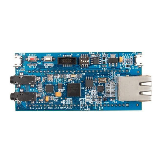
Page 10: Lpc1830-Xplorer Pin Out
Quick Start Guide: LPC4330-Xplorer 2.4 LPC1830-Xplorer pin out Fig.10 2.5 LPC1830 description The LPC1830 is a high-performance, cost-effective Cortex-M3 microcontroller featuring 200 kB of SRAM, and advanced peripherals including Ethernet, High Speed USB 2.0 Host/OTG/Device and CAN 2.0B. Operating at speeds up to 180 MHz, the LPC1830 also features two new configurable peripherals: a SPI Flash Interface and a State Configurable Timer. - Page 11 Quick Start Guide: LPC4330-Xplorer • 10/100T Ethernet MAC with RMII and MII interfaces and DMA support • One High-speed USB 2.0 Host/Device/OTG interface with DMA support • One High-speed USB 2.0 Host/Device interface with DMA support • Four 550 UARTs with DMA support: one UART with full modem interface •...
-
Page 12: Lpc1830-Xplorer Verification
Quick Start Guide: LPC4330-Xplorer 3.0 LPC1830-Xplorer verification NGX's evaluation platforms ship with a factory-programmed test firmware that verifies all the on-board peripherals. It is highly recommended that you verify the board, before you start programming. Also this exercise helps you get acclimatized with the board quickly. -
Page 13: Powering The Board
However for the power up reset (USB power cycle) the controller boots up fine. Power up the board over USB1 port and we are all set to verify the LPC1830-Xplorer peripherals. Before we get to the verification we need to install the Virtual COM port drivers needed for the LPC1830-Xplorer (USB1 port) to appear as a Virtual COM port (Used for viewing the debug messages on serial emulation tool). - Page 14 Quick Start Guide: LPC4330-Xplorer Step 1: Connect USB1 to the computer, Open device manager, you can find “NXP LPC18xx VCOM” new device listed under ‘Other devices’. Fig.12 Step 2: Right click on the “NXP LPC18xx VCOM” and then left click on ‘Update Driver Software’. Fig.13 Page | 14...
- Page 15 Quick Start Guide: LPC4330-Xplorer Step 3: Click on Browse my computer for driver software. Fig.14 Step 4: Click Browse, select downloaded LPC1830_Xplorer_VCOM_inf unzipped driver folder and then click on OK. Fig.15 Page | 15...
- Page 16 Quick Start Guide: LPC4330-Xplorer Step 5: Click on Next to continue driver installation. Fig.16 Step 6: Click on ‘Install this driver software anyway’. Fig.17 Page | 16...
- Page 17 Quick Start Guide: LPC4330-Xplorer Step 7: The ‘LPC18xx USB VCom driver’ is successfully installed, click on close. Fig.18 Step 8: Now ‘LPC18xx USB VCom Port’ (COM12) is ready to use. Fig.19 Note: The Virtual COM is listed under the device manager. Please note that the COM port list under the Device Manager is automatically updated with the COM port number for the Virtual COM.
- Page 18 Quick Start Guide: LPC4330-Xplorer The orders in which the on-board peripherals are verified by the firmware are as follows: Test Firmware Flowchart: START Ethernet PHY Verification Is VCOM Enumeration Completed? Audio codec Verification Wait for user input flag == 1? Xplorer peripheral initialization USB0 HID...
-
Page 19: Leds
Quick Start Guide: LPC4330-Xplorer 3.3.1 LEDs Test setup and verification: As soon as the Xplorer is turned ON or reset; the test LEDs go ON & OFF for a couple of times, this simple test validates the LEDs. The Xplorer has one Green LED and one Blue LED. These LEDs are also connected to the outputs of the SCT lines. - Page 20 Quick Start Guide: LPC4330-Xplorer Step 2: Select ‘USB1 Vcom Port’ (COM12) and click on OK. Fig.21 Step 3: Click on ‘Restore Defaults’ and click on OK. Fig.22 Page | 20...
- Page 21 Quick Start Guide: LPC4330-Xplorer Step 4: Now the ‘USB1 VCom’ is ready to use. Fig.23 Note: You would not be able to proceed with the verification unless the Virtual COM drivers are installed. The firmware waits for the USB1 to enumerate as VCOM port. Page | 21...
-
Page 22: User Input Switch
Quick Start Guide: LPC4330-Xplorer 3.3.3 User Input Switch Test setup and verification: Once the VCOM drivers are installed the Xplorer waits for the User Input Switch to be pressed. Only after detecting a user button (SW2) press the test firmware proceeds with validating other peripherals. This synchronization is necessary to ensure that the debug messages on the VCOM port can be viewed from the start of the test. -
Page 23: Usb0 (Hid Device)
Quick Start Guide: LPC4330-Xplorer 3.3.4 USB0 (HID device) Test setup and verification: Connect the USB cable to USB0 connector. The USB enumeration can be checked in device manager. The Xplorer enumerates as a Human Interface Device (HID). On a Windows machine this can be confirmed by looking in to the ‘Device Manager’... -
Page 24: Ethernet
Quick Start Guide: LPC4330-Xplorer 3.3.5 Ethernet Test setup and verification: The test firmware configures the Xplorer board as a webserver. Fig.26 The ethernet interface can be verified by either using a PING command in the windows command prompt. Fig.27 Page | 24... -
Page 25: Micro Sd Connector
Quick Start Guide: LPC4330-Xplorer The IP address of the Xplorer board is configured as 192.168.1.123. Type the same IP address in the browser. Clicking the ON button will TURN-ON LED D3 and clicking OFF button will TURN-OFF LED Fig.28 3.3.6 Micro SD connector Test setup and verification: The firmware validates the micro SD card interface by writing and reading a sector of the SD card connected. -
Page 26: Audio Interface
Quick Start Guide: LPC4330-Xplorer 3.3.7 Audio Interface Test setup and verification: For the audio interface the LPC1830 Xplorer incorporates external audio codec from NXP. The codec is interfaced to the MCU over I2S0 for data and over I2C0 for command interface. The test firmware verifies both the audio-in and audio-out path. - Page 27 DEMONSTRATION, and EDUCATION OR EVALUATION PURPOSES ONLY and is not considered by NGX Technologies Pvt. Ltd to be a finished end-product fit for general consumer use. Persons handling the product(s) must have electronics training and observe good engineering practice standards. As such,...
- Page 28 NGX Technologies reserves the right to make changes to information published in this document, at any time and without notice, including without limitation specifications and product descriptions. This document replaces and supersedes all information supplied prior to the publication hereof.
Need help?
Do you have a question about the LPC1830-Xplorer and is the answer not in the manual?
Questions and answers