Advertisement
Table of Contents
1. What is SMI?
2. Safety precautions
3. Technical data
4. Hardware
4.1 Overview IF SMI RS-485
4.1.1 RS-485 User interface
4.1.2 RS-485 BUS
4.1.3 Power supply
4.1.4 SMI BUS
4.1.5 Master Up/Down button
4.1.6 Base Address
4.2 Termination RS-485 BUS
5. Menu navigation
5.1 Power-up
5.2 Main menu
5.3 Menu navigation
5.4 Address menu
5.5 Modify base address
5.6 Show error
5.7 Error log menu
5.8 Soft RESET
6. Protocol
6.1 Message structure
6.2 CRC16 Calculation
6.3 Steer commands
6.3.1
MSG_UP
6.3.2
MSG_DOWN
6.3.3
MSG_STOP
6.3.4
MSG_STEP_UP
6.3.5
MSG_STEP_DOWN
6.3.6
MSG_SET_POS
6.3.7
MSG_SET_TILT
6.3.8
MSG_SET_POS_STEP_UP
6.3.9
MSG_SET_POS_STEP_DOWN
6.3.10 MSG_GOTO_POS1
6.3.11 MSG_GOTO_POS2
6.3.12 MSG_GETMANID
6.3.13 MSG_SMI_TUNNEL
6.3.14 MSG_GW_OPTIONS
6.3.15 MSG_ERROR
6.4 Maintenance commands
6.4.1
MSG_VERSION
6.4.2
MSG_AUTO_ADDR
6.4.3
MSG_GET_SER
6.4.4
MSG_SET_SMIID
6.4.5
MSG_GET_PAR
6.4.6
MSG_GET_POS1
6.4.7
MSG_SET_POS1
6.4.8
MSG_GET_POS2
6.4.9
MSG_SET_POS2
6.5 Status commands
6.5.1
MSG_GETGENSTAT
6.5.2
MSG_GETDETSTAT
7. PC Test Software
7.1 Communication
7.2 General commands
7.3 Motor Mask based commands
7.4 Motor ID based commands
7.5 Send / Receive
8. Wiring diagrams
8.1 IF SMI RS-485 LoVo
8.2 IF SMI RS-485 230VAC
© Vestamatic GmbH
G
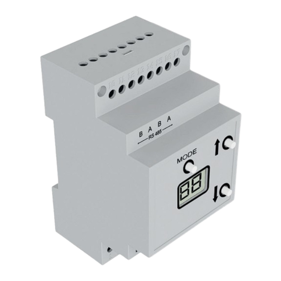
IF SMI RS-485 DIN RAIL
Contents
IF SMI RS-485 24 VDC-DIN
Motor control SMI RS-485 for top-hat rail
for control of 16 SMI motors 24 VDC.
IF SMI RS-485 230 VAC-DIN
Motor control SMI RS-485 for top-hat rail
for control of 16 SMI motors 230 VAC.
Installation and Operating Instructions
1. What is SMI?
SMI is the abbreviation for Standard Motor Interface. SMI has been de-
veloped for the connection of intelligent drives for roller shutters and
sun protection systems. SMI enables to transmit telegrams from control
system to the drive and vice versa. With SMI it is possible to combine
products from different sources together. The SMI Interface should spread
high value solutions and promote drives and controls on the market. The
applications in roller shutters and sun protection systems require extreme
robustness and economic efficiency. SMI has been developed to meet
these requirements.
2. Safety precautions
Ä
– Contact a professional electrician for installation.
– Check the control system for signs of mechanical damage after
unpacking. If you notice any shipping damage, do not start up
the control system and notify your supplier imme di ately.
– The control system should only be used for the purpose speci-
fied by the manufacturer (refer to the operating instructions).
Any changes or modifications thereof are not permissible and
will result in loss of all warranty claims.
– If the control unit cannot be operated without presenting a
hazard, it must be switched off and prevented from being
switched on unintentionally.
– Turn off the power supply and prevent it from being switched
on unintentionally before performing work on any windows,
control or sunshades driven by the control system.
3. Technical data
Article
Supply voltage:
Impulse voltage withstand level: kV
Rated power:
Operating temperature:
IP class:
Degree of contamination:
Dimensions (H × W × D):
Conformity:
1/10
G
IF SMI RS-485 DIN
Art.-no.: 01092124
Art.-no.: 01092714
IF SMI RS-485 DIN
Art.-no.: 01092124
01092714
230 VAC
2.5
W
2 W
°C
0 °C (32 °F) to +40 °C (104 °F)
IP
20
2
mm
90 × 52 × 60 (3 HP)
p
Subject to modifications.
Advertisement
Table of Contents

Related Manuals for Vestamatic IF SMI RS-485 DIN RAIL Series


Summary of Contents for Vestamatic IF SMI RS-485 DIN RAIL Series
- Page 1 7. PC Test Software 7.1 Communication 7.2 General commands 7.3 Motor Mask based commands 7.4 Motor ID based commands 7.5 Send / Receive 8. Wiring diagrams 8.1 IF SMI RS-485 LoVo 8.2 IF SMI RS-485 230VAC 1/10 © Vestamatic GmbH Subject to modifications.
- Page 2 RS-485 BUS, which makes it possible to control 16 x 16 = 256 A blinking dot in the right bottom corner with a blink-frequency of 1 Hz „ SMI motors. to indicate a running application. 2/10 © Vestamatic GmbH Subject to modifications.
-
Page 3: Menu Navigation
After 10 seconds pressing the MODE button, the soft-reset will be entered, and display will briefly show the following: 5.6 Show error When an error occurs, this will be shown directly. 3/10 © Vestamatic GmbH Subject to modifications. -
Page 4: Message Structure
The position of each sun blind can be obtained by the detailed response message MSG_GETDETSTAT. The IF SMI RS-485 module responds to this request with a general status message MSG_GETGENSTAT. The position of each sun blind can be obtained by the detailed response message MSG_GETDETSTAT. 4/10 © Vestamatic GmbH Subject to modifications. - Page 5 REMARK: An Manufacturer ID of 0 indicates that an invalid SMI-ID is REMARK: The MSG_SET_TILT message uses a manufacturer specific used. SMI command, which is currently only supported by Vesta- matic SMI motors. 5/10 © Vestamatic GmbH Subject to modifications.
- Page 6 [OPTIONS]: Stored gateway options. #define MSG_SET_SMIID 0x23 See gateway options layout as described above. #define MSG_GET_PAR 0x24 Default gateway options: 0x00 #define MSG_GET_POS1 0x28 #define MSG_SET_POS1 0x29 #define MSG_GET_POS2 0x2A #define MSG_SET_POS2 0x2B 6/10 © Vestamatic GmbH Subject to modifications.
- Page 7 SMI address of motor (0..15) to set. [POS1]: MSB of 16-bit intermediate position 2. [MAN]: Manufacturer ID of SMI motor. Manufacturer ID for a Vestamatic The intermediate position value is defined as below: motor is 6. 0x0000 is the top position (0%).
- Page 8 [TILT]: Orientation of the slats REMARK: Tilt information uses a manufacturer specific SMI command, which is currently only supported by Vestamatic SMI motors. For non Vestamatic SMI-motors, TILT value 0x00 is returned. [CYCLE0..3]: 32-bits cycle counter of the motor 7.1 Communication Status Bit layout In the “Communication”...
- Page 9 “6. Protocol” for detailed information. 7.5 Send / Receive In the “Send/Receive” section, you can monitor the communication between PC and IF SMI RS-485 module. You will see the Transmit and Receive data stream. 9/10 © Vestamatic GmbH Subject to modifications.
- Page 10 IF SMI RS-485 DIN 8. Wiring diagrams 8.1 Wiring diagram – IF SMI RS-485 24VDC DIN 8.2 Wiring diagram – IF SMI RS-485 230VAC DIN 10/10 © Vestamatic GmbH Subject to modifications.
Need help?
Do you have a question about the IF SMI RS-485 DIN RAIL Series and is the answer not in the manual?
Questions and answers