Table of Contents
Advertisement
Quick Links
Advertisement
Table of Contents

Related Manuals for BERTHOLD TECHNOLOGIES Uni-Probe LB 490


Summary of Contents for BERTHOLD TECHNOLOGIES Uni-Probe LB 490
- Page 1 Process Control Level Measurement Uni-Probe LB 490 With All Supplements User’s Manual ID no. 38477BA2B Rev. no.: 05 25.5.09 Embedded Soft. Rev. 100 Device Description 03 HART Device Description 01 PA Device Description 02 FF...
- Page 3 Volume 1: Safety Manuals Volume 2: Uni-Probe Installation ® Volume 3: HART Communicator User Interface ™ Volume 4: PACTware User Interface FDT/DTM ® Volume 5: SIMATIC PDM User Interface HART Volume 6: SIMATIC PDM User Interface Profibus PA ™ Volume 7: FOUNDATION Fieldbus User Interface...
- Page 4 General Information Thank you very much for purchasing the level gauging system Dear customers Uni-Probe LB 490 made by BERTHOLD TECHNOLOGIES GmbH & Co. KG. The scope of supply also includes this User’s Manual. Be sure to have this User’s Manual always to hand.
-
Page 5: Table Of Contents
9.1 Scope of Application ..........1 – 61 9.2 Use and Function............1 – 63 9.3 Safety Function............1 – 64 9.4 Safety Requirement ..........1 – 64 9.5 Project Planning............1 – 65 Uni-Probe LB 490 BERTHOLD TECHNOLOGIES GmbH & Co. KG... - Page 6 Contents Volume 1-7 9.6 Getting Started............1 – 67 9.7 Behavior during Operation and during Malfunctions . 1 – 69 9.8 Recurrent Performance Test ........1 – 70 9.9 Safety-Technical Data..........1 – 71 9.10 Certificate Functional Safety ........1 – 73 Safety Instructions for the Types of Protection ATEX / FM / CSA ...............
- Page 7 1.5 Technical Data ............2 – 130 1.6 Detector Codes ............2 – 133 1.7 Uni-Probe LB 490 Nomenclature ......2 – 134 1.8 LB 490 Super-Sens Nomenclature ......2 – 135 1.9 LB 490 Tower-Sens Nomenclature ......2 – 136 Installation ..............
- Page 8 Contents Volume 1-7 4.9 Replacing the Plastic Scintillator ......2 – 229 4.10 Replacing the Digital Board........2 – 231 4.11 Replacing the Power Supply Unit ......2 – 234 4.12 Replacing Fuses ............2 – 236 4.13 Updating the Embedded Software in the Uni-Probe 2 – 237 4.14 Check Detector ............
- Page 9 ........3 – 327 2.31 S ERVICE ..............3 – 328 2.32 T ALCULATION ..........3 – 329 2.33 I/O T ............. 3 – 329 2.34 S TATUS NPUT ..........3 – 330 Uni-Probe LB 490 BERTHOLD TECHNOLOGIES GmbH & Co. KG...
- Page 10 Contents Volume 1-7 2.35 D UTPUT ..........3 – 330 2.36 C URRENT UTPUT ..........3 – 331 2.37 P ROBE ETTINGS ..........3 – 332 2.38 HV S ETTINGS ............3 – 334 2.39 P LATEAU ............... 3 – 335 2.40 HART I NTERFACE ..........
- Page 11 PC Connection to the Uni-Probe ........4 – 407 Installing and Working with DTM ........4 – 409 2.1 Requirements ............4 – 409 2.2 FDT Container ............4 – 409 2.3 DTM Communication Software....... 4 – 411 Uni-Probe LB 490 BERTHOLD TECHNOLOGIES GmbH & Co. KG...
- Page 12 3.1 How to Get Started ..........5 – 427 3.2 Installing SIMATIC PDM .......... 5 – 427 3.3 Installing the Uni-Probe LB 490 Device Description.. 5 – 432 3.4 Project Setup ............5 – 434 3.5 Start SIMATIC PDM..........5 – 438 Menu Overview ..............
- Page 13 9.3 Corrective Action............ 5 – 545 9.4 Reset ..............5 – 546 9.5 Operation Modes during Measurement ....5 – 547 9.6 Error Reset.............. 5 – 547 9.7 Fault Current ............5 – 548 Uni-Probe LB 490 BERTHOLD TECHNOLOGIES GmbH & Co. KG...
- Page 14 Contents Volume 1-7 Volume 6 SIMATIC PDM User Interface Profibus PA Process Operation ............6 – 555 1.1 Important Information on the Profibus PA Operation............... 6 – 555 ® 1.2 Alternative Operation via HART ......6 – 555 1.3 System Overview ............ 6 – 556 Installation / Program Start..........
- Page 15 Installation / Program Start ..........7 – 663 2.1 Installing the Device Description......7 – 663 2.2 Addressing the Uni-Probe LB 490 Level System ..7 – 663 Parameter Overview ............7 – 665 3.1 Parameters for the Function Block Resource.... 7 – 665 3.2 Parameters for the Function Block Transducer ..
- Page 16 Contents Volume 1-7 Error Handling ..............7 – 715 7.1 Device Response in Case of Error ......7 – 715 7.2 Error Handling Modes..........7 – 716 7.3 Operation Modes during Measurement ....7 – 716 7.4 Corrective Action............ 7 – 717 7.5 Reset ..............
- Page 17 Volume 1 Safety Manuals...
- Page 18 Volume 1 38477BA2B 1 – 18 25.5.09...
-
Page 19: About This User's Manual
SMALL CAPS indicate commands or menu items. The term BERTHOLD TECHNOLOGIES in this User’s Manual stands for the company BERTHOLD TECHNOLOGIES GmbH & Co. KG. Please observe the warnings and safety instructions given in this User’s Manual to rule out physical injury and property damage. -
Page 20: Further Symbols
1 About this User’s Manual Volume 1 Further Symbols Warning sign: Never step under hovering loads Warning sign: Nuclear radiation Warning sign: Explosion protection Warning sign: Risk of crushing Instruction: Disconnect from mains supply Instruction: Wear hard hat Instruction: Wear safety shoes 38477BA2B 1 –... -
Page 21: General Instructions
– the characteristic data, limit values and the information on the operating and environmental conditions on the type labels and data sheets – the signs on the devices Uni-Probe LB 490 1 – 21 BERTHOLD TECHNOLOGIES GmbH & Co. KG... - Page 22 1 About this User’s Manual Volume 1 38477BA2B 1 – 22 25.5.09...
-
Page 23: Use And Function
2 Use and Function Use and Function The Uni-Probe LB 490 has been designed as a level gauging system and may be used only for this purpose. If it is used in any manner not described in this User’s Manual, the protection of the device is impaired and all warranty claims are voided. - Page 24 Explosion hazard! Spare parts for detectors used in hazardous areas may only be installed by BERTHOLD TECHNOLOGIES service staff or by persons authorized by BERTHOLD TECHNOLOGIES. If this is not possible, you have to replace the complete detector or return it to the man- ufacturer for repair.
-
Page 25: Qualification Of Personnel
IMPORTANT At least specialized persons are required for all work on and with the Uni-Probe LB 490, under the guidance of a qualified or autho- rized person. Specialized Persons Specialized persons are e.g. technicians or welders who can carry out various tasks in transportation, assembly and installation of the Uni-Probe LB 490 under the supervision of an authorized person. -
Page 26: Qualified Persons
Authorized persons are persons, who are foreseen for certain activ- ities as a consequence of statutory provisions, or who have been approved by BERTHOLD TECHNOLOGIES for carrying out certain activities. The Radiation Safety Officer has to be involved whenever radioactive substances are being handled. -
Page 27: Transport And Assembly
Uni-Probe cannot be used any more in ex-protected areas. If the Uni-Probe housing receives a mechan- ical blow, e.g. because it is dropped, then you have to return the Uni-Probe to BERTHOLD TECHNOLOGIES GmbH & Co. KG for inspection. Uni-Probe LB 490 1 –... - Page 28 4 Transport and Assembly Volume 1 38477BA2B 1 – 28 25.5.09...
-
Page 29: Electrical Installation
If the housing is open, you may get in contact with live parts if the power supply is turned on. During installation and servicing on the hardware of the Level Gauge Uni-Probe LB 490 you have to discon- nect the system, possibly connected relay contacts and all in- and outputs from power to avoid getting in contact with live parts. - Page 30 When you open the instrument: Please take precautions when working with printed circuit boards (ESD). Dis- charge yourself before touching the components by touching a grounding point. Please contact BERTHOLD TECHNOLOGIES if you need any further information. 38477BA2B 1 – 30...
-
Page 31: Radiation Protection
The total sum of the radiation dose absorbed by a body is deter- mined by three factors. On the basis of these factors, certain fun- damental radiation protection rules can be derived: Uni-Probe LB 490 1 – 31 BERTHOLD TECHNOLOGIES GmbH & Co. KG... - Page 32 6 Radiation Protection Volume 1 This means the distance between the radioactive source and the Distance human body. The radiation intensity (dose rate) decreases - like light - in proportion to the square of the distance; this means, dou- bling the distance to the source will reduce the dose rate to one quarter.
-
Page 33: General Radiation Protection Instructions
Installation, dismantling, relocation, maintenance, testing involving the radioactive source, or its shielding shall ONLY be performed under the supervision of the Radiation Safety Officer. Please contact BERTHOLD TECHNOLOGIES if you need any further information. Uni-Probe LB 490 1 – 33... -
Page 34: Mounting The Shielding
6 Radiation Protection Volume 1 Mounting the Shielding 6.3.1 Safety Instructions To keep the radiation exposure of the assembling personnel as low as possible, only licensed personnel who have been trained on how to handle radioactive substances are allowed to assemble or disas- semble the shielding with the source. - Page 35 30: 350MBq 0.35μSv m 0.5h × × × 8.2μSv ------------------------------------------------------------------------------------------- - 0.5m h MBq × × × Uni-Probe LB 490 1 – 35 BERTHOLD TECHNOLOGIES GmbH & Co. KG...
- Page 36 6 Radiation Protection Volume 1 6.3.4 Testing the Shutter Mechanism This procedure ensures that the shutter mechanism is operating correctly and that the shutter is closed and the source is completely shielded when CLOSED is indicated by the device handle or cylin- der.
-
Page 37: Safety Measures
In the event that radioactive substances are lost, the Radiation Safety Manager and the regulatory authority have to be notified immediately. In case of theft, the police must be informed as well. Uni-Probe LB 490 1 – 37 BERTHOLD TECHNOLOGIES GmbH & Co. KG... -
Page 38: Accidents, Loss, Damage, Fire, Theft
• Limit access to the area. • Report the incident to BERTHOLD TECHNOLOGIES; who will advise what further immediate precautions to take and arrange for quick support from a licensed person. In case of loss or theft, notify the regulatory authority. - Page 39 In case of an accident or malfunction or any other event which affects the safety, the regulatory authority has to be informed and also, if necessary, the authority in charge of public safety. Please contact BERTHOLD TECHNOLOGIES if you need any further infor- mation. Uni-Probe LB 490 1 –...
-
Page 40: Shielding And Source
6 Radiation Protection Volume 1 Shielding and Source Shieldings do not include any wearing parts or mechanically mov- ing parts that under normal operating conditions require mainte- nance. For safety reasons, however, it should be possible any time to lock the useful beam. A function check has to be performed in appropriate intervals of max. - Page 41 (here: November) and the third the year the source was manufactured (here: 1994). It is included on the identity plate of the shielding and also on the seal certificate that comes with every source. Uni-Probe LB 490 1 – 41 BERTHOLD TECHNOLOGIES GmbH & Co. KG...
-
Page 42: Leak Test
6 Radiation Protection Volume 1 Leak Test Depending on the regulatory authority responsible for the sources employed in their territory, regularly recurring leak tests have to be carried out. These tests have to be carried out by authorized tech- nical experts. The appropriate documents on the source have to be provided in order to carry out this test. - Page 43 The alternative test area is the visible part on the head of the For point source shieldings with shielding cylinder. rotary shutter Alternative test area Figure 6-4 Alternative test area on point source shieldings Uni-Probe LB 490 1 – 43 BERTHOLD TECHNOLOGIES GmbH & Co. KG...
- Page 44 6 Radiation Protection Volume 1 38477BA2B 1 – 44 25.5.09...
-
Page 45: Source Replacement
• Allan keys in the required sizes. • 2 pairs of pliers to take hold of source and source holder. Uni-Probe LB 490 1 – 45 BERTHOLD TECHNOLOGIES GmbH & Co. KG... - Page 46 7 Source Replacement Volume 1 Cordon off an area consistent with the activity of the source. Pre- vent persons from approaching. If sufficient space is available, the source can be replaced in the shielding installed at the measuring site. To this end, bring the new source in its transport shielding close to the measuring site.
- Page 47 IMPORTANT The special regulations regarding labeling and transport of the shielding back to the manufacturer have to be observed. If in doubt, please contact BERTHOLD TECHNOLOGIES' Source Trans- port Manager. This completes the point source replacement. Uni-Probe LB 490 1 –...
-
Page 48: Rod Source Replacement
7 Source Replacement Volume 1 Rod Source Replacement This section describes how to replace rod source in the following shieldings: – Type 80 – Type 100 – Type 120 – Type 150 – Type 200 – Type 270 Radioactive sources may be replaced only by competent and licensed persons, taking into account official regulations. -
Page 49: Shielding1
7-3 on page 1–50). With multi-part sources, the rings on the rod source indicate the installation order and position. It is important to observe these instructions when replacing a source. Uni-Probe LB 490 1 – 49 BERTHOLD TECHNOLOGIES GmbH & Co. KG... - Page 50 7 Source Replacement Volume 1 Shielding Rod sources Top: 1 ring Bottom: 2 rings Figure 7-3 Markings on multi-part sources and shieldings 7.2.1 Procedure for Source Replacement Figure 7-4 Dismounting rod source shielding Unscrew the head flange (1) using a suitable Allan key. ...
- Page 51 IMPORTANT The special regulations regarding labeling and transport of the shielding back to the manufacturer have to be observed. If in doubt, please contact BERTHOLD TECHNOLOGIES' Source Trans- port Manager. This completes the source replacement. Uni-Probe LB 490 1 – 51...
- Page 52 7 Source Replacement Volume 1 Point Source Replacement on Rotary Cylinder Shielding This section describes how to replace point sources in the following shieldings: – Type 80 – Type 100 – Type 120 – Type 150 – Type 200 – Type 270 When replacing a source, you have to work with the unshielded source for a short time.
- Page 53 Do not push the pipe wrench tight too much to prevent damage to the source. Hold the source far Uni-Probe LB 490 1 – 53 BERTHOLD TECHNOLOGIES GmbH & Co. KG...
- Page 54 IMPORTANT The special regulations regarding labeling and transport of the shielding back to the manufacturer have to be observed. If in doubt, please contact BERTHOLD TECHNOLOGIES' Source Trans- port Manager. This completes the source replacement. 38477BA2B 1 – 54...
-
Page 55: Radiation Exposure During Source Replacement
If the above assumptions do not apply, the calculations have to be corrected accordingly. Actually, it can only be another working time which has a proportional effect on the result of the calculated dose rate. Uni-Probe LB 490 1 – 55 BERTHOLD TECHNOLOGIES GmbH & Co. KG... - Page 56 7 Source Replacement Volume 1 38477BA2B 1 – 56 25.5.09...
-
Page 57: Source Disposal
• Radioactive material can be returned only after you have received permission from BERTHOLD TECHNOLOGIES. We would be happy to send you a quotation on the disposal costs to be expected. Uni-Probe LB 490 1 –... - Page 58 8 Source Disposal Volume 1 • The radioactive material has to be shipped to Wildbad carriage paid. BERTHOLD TECHNOLOGIES does not take over any costs for customs clearance or transport. • BERTHOLD TECHNOLOGIES has to be informed in advance about the return transport. Radioactive material that is shipped to Berthold without prior notice will not be accepted by BERTHOLD TECHNOLOGIES.
- Page 59 Telephone no.: Town / Postal code Country: Activity Source No. Isotope Source will be returned for disposal Other instructions (please complete) ........................................................... Shielding may be disposed off Uni-Probe LB 490 1 – 59 BERTHOLD TECHNOLOGIES GmbH & Co. KG...
- Page 60 8 Source Disposal Volume 1 New sources to be inserted in the shielding(s) according to sender's order no.: ....../ our order confirmation no. Shielding to be returned empty to sender Shielding to be returned to sender after repair Sender's repair order no.: ....../ our order confirmation no. Return of a shielding on loan from sender Sender's order no.: ....../ our order confirmation no.
-
Page 61: Functional Safety
Shielded source Uni-Probe LB 490 Current output - Co-60 4–20mA - Cs-137 with mechanical locking mechanism Figure 9-1 Overview measuring system with Uni-Probe LB 490 The information applies to the following device versions: DEVICE Description Hardware Software revision revision Level... - Page 62 9 Functional Safety Volume 1 The software revision can be viewed on the Device Description menu, menu item REVIEW The hardware revision (Device Rev.) is indicated on the outside of the housing and inside the connection box. 38477BA2B 1 – 62 25.5.09...
-
Page 63: Use And Function
Volume 1 9 Functional Safety Use and Function The Level Gauge Uni-Probe LB 490 is employed for continuous level measurement and monitoring and for the detection of limit levels of liquids and bulk material in and pipelines. Source Measuring system LB 490... -
Page 64: Safety Function
9 Functional Safety Volume 1 Safety Function The safety function of the measuring system comprises the mea- surement and detection of levels caused by the presence of product being measured in the measuring path between radiation source and measuring system. Safety Requirement Safety integrity level Operating mode with low... -
Page 65: Project Planning
(MTTR = 8h). • In the operating mode with low demand rate the reaction time of the LB 490 to dangerous detected faults is max. 15 minutes. Uni-Probe LB 490 1 – 65 BERTHOLD TECHNOLOGIES GmbH & Co. KG... - Page 66 9 Functional Safety Volume 1 • In the operating mode with high demand rate the reaction time of the LB 490 to dangerous apparent faults is max. 1 day. If the demand rate is not more than once a year, the measuring device may be operated as a safety-relevant sub-system in the operating mode with low demand rate (IEC 61508-4, 3.5.12).
-
Page 67: Getting Started
User’s Manual. See Volume 3, chapter "4.3.2 Empty Cali- bration". Full calibration The level must be above the measuring range. If this is not possible, you may also close the source shielding. If only the Uni-Probe LB 490 1 – 67 BERTHOLD TECHNOLOGIES GmbH & Co. KG... - Page 68 Make sure that the absorption of the closed shielding nearly corresponds to the absorption of the product. If in doubt, please contact BERTHOLD TECHNOLOGIES or your local repre- sentative. – Full calibration has to be carried out as described in the User’s Manual.
-
Page 69: Behavior During Operation And During Malfunctions
Replacement of the measuring system is rather simple; it is described in the User’s Manual. • If parts are replaced as a result of a detected failure, please inform BERTHOLD TECHNOLOGIES accordingly (including fail- ure description). • If modifications in the product, the gas pressure, or the con- struction of the tank in the area of the radiation path are car- ried out, the measurement has to be calibrated again. -
Page 70: Recurrent Performance Test
9 Functional Safety Volume 1 Recurrent Performance Test The recurrent performance test is used to check the safety function to uncover possibly undetected dangerous failure. The operational capability of the measuring system has to be checked in adequate intervals. It is in the responsibility of the operator to select the type of test and the proof test interval. -
Page 71: Safety-Technical Data
= 2 years <0.064 x 10 Proof = 5 years <0.160 x 10 Proof HFT = 1 (Hardware Fault Tolerance) Two-channel architecture 1002 Shielding with source 2 Uni-Probes Tank Uni-Probe LB 490 1 – 71 BERTHOLD TECHNOLOGIES GmbH & Co. KG... - Page 72 9 Functional Safety Volume 1 1. For common cause ß = 2% = (PFD + ß x PFD 1002 1001 1001 = 1 year <6.5 x 10 Proof = 2 years <13.2 x 10 Proof = 5 years <34.5 x 10 Proof 2.
-
Page 73: Certificate Functional Safety
Volume 1 9 Functional Safety 9.10 Certificate Functional Safety Uni-Probe LB 490 1 – 73 BERTHOLD TECHNOLOGIES GmbH & Co. KG... - Page 74 9 Functional Safety Volume 1 38477BA2B 1 – 74 25.5.09...
- Page 75 Volume 1 9 Functional Safety Uni-Probe LB 490 1 – 75 BERTHOLD TECHNOLOGIES GmbH & Co. KG...
- Page 76 9 Functional Safety Volume 1 38477BA2B 1 – 76 25.5.09...
- Page 77 Volume 1 9 Functional Safety Uni-Probe LB 490 1 – 77 BERTHOLD TECHNOLOGIES GmbH & Co. KG...
- Page 78 9 Functional Safety Volume 1 38477BA2B 1 – 78 25.5.09...
- Page 79 Volume 1 9 Functional Safety Uni-Probe LB 490 1 – 79 BERTHOLD TECHNOLOGIES GmbH & Co. KG...
- Page 80 9 Functional Safety Volume 1 38477BA2B 1 – 80 25.5.09...
- Page 81 Volume 1 9 Functional Safety Uni-Probe LB 490 1 – 81 BERTHOLD TECHNOLOGIES GmbH & Co. KG...
- Page 82 9 Functional Safety Volume 1 38477BA2B 1 – 82 25.5.09...
-
Page 83: Safety Instructions For The Types Of Protection Atex / Fm / Csa
BERTHOLD TECHNOLOGIES. Prerequisite for working in these areas is that the personnel knows all applicable rules and regulations. Users have to keep in mind: –... - Page 84 Spare parts for measuring devices used in the ex-area may only be Repair and spare part exchange installed by the BERTHOLD TECHNOLOGIES service or by service engineers authorized by BERTHOLD TECHNOLOGIES. If this is not possible, the complete detector has to be returned to the manufac- turer for repair.
-
Page 85: Overview Ex-Versions
IP66 T80°C IP66 T80°C Signal output intrinsically safe Ex temp. range -40 … +60°C -20 … +50°C -20 … +60°C -40 … +60°C -20 … +60°C -40 … +60°C Uni-Probe LB 490 1 – 85 BERTHOLD TECHNOLOGIES GmbH & Co. KG... - Page 86 10 Safety instructions ATEX/FM/CSA Volume 1 Ex temp. range -40 … +80°C -20 … +50°C -20 … +60°C -40 … +80°C -20 … +60°C -40 … +80°C Operat. temp. -40 … +50°C -20 … +50°C -20 … +50°C -40 … +50°C -20 …...
-
Page 87: Type Of Protection Atex
The tightening torques for the screwed cable glands supplied by BERTHOLD TECHNOLOGIES are listed in the technical documents in chapter 5, page 2–247. Uni-Probe LB 490 1 –... -
Page 88: Type Of Protection Fm/Csa
10 Safety instructions ATEX/FM/CSA Volume 1 Armoured cables Special screwed cable glands are needed for armoured cables. How to install these cables is described in the installation instructions for the cable conduits used. 10.2.1 Characteristic Features of Versions with Intrin- sically Safe Current Output •... -
Page 89: Certificates
Volume 1 11 Certificates Certificates 11.1 ATEX Certificate Uni-Probe LB 490 1 – 89 BERTHOLD TECHNOLOGIES GmbH & Co. KG... - Page 90 11 Certificates Volume 1 38477BA2B 1 – 90 25.5.09...
- Page 91 Volume 1 11 Certificates Uni-Probe LB 490 1 – 91 BERTHOLD TECHNOLOGIES GmbH & Co. KG...
- Page 92 11 Certificates Volume 1 38477BA2B 1 – 92 25.5.09...
- Page 93 Volume 1 11 Certificates Uni-Probe LB 490 1 – 93 BERTHOLD TECHNOLOGIES GmbH & Co. KG...
- Page 94 11 Certificates Volume 1 38477BA2B 1 – 94 25.5.09...
- Page 95 Volume 1 11 Certificates Uni-Probe LB 490 1 – 95 BERTHOLD TECHNOLOGIES GmbH & Co. KG...
- Page 96 11 Certificates Volume 1 38477BA2B 1 – 96 25.5.09...
- Page 97 Volume 1 11 Certificates Uni-Probe LB 490 1 – 97 BERTHOLD TECHNOLOGIES GmbH & Co. KG...
- Page 98 11 Certificates Volume 1 38477BA2B 1 – 98 25.5.09...
- Page 99 Volume 1 11 Certificates Uni-Probe LB 490 1 – 99 BERTHOLD TECHNOLOGIES GmbH & Co. KG...
- Page 100 11 Certificates Volume 1 38477BA2B 1 – 100 25.5.09...
- Page 101 Volume 1 11 Certificates Uni-Probe LB 490 1 – 101 BERTHOLD TECHNOLOGIES GmbH & Co. KG...
- Page 102 11 Certificates Volume 1 38477BA2B 1 – 102 25.5.09...
- Page 103 Volume 1 11 Certificates Uni-Probe LB 490 1 – 103 BERTHOLD TECHNOLOGIES GmbH & Co. KG...
- Page 104 11 Certificates Volume 1 38477BA2B 1 – 104 25.5.09...
- Page 105 Volume 1 11 Certificates Uni-Probe LB 490 1 – 105 BERTHOLD TECHNOLOGIES GmbH & Co. KG...
- Page 106 11 Certificates Volume 1 38477BA2B 1 – 106 25.5.09...
- Page 107 Volume 1 11 Certificates Uni-Probe LB 490 1 – 107 BERTHOLD TECHNOLOGIES GmbH & Co. KG...
-
Page 108: Fm Certificate
11 Certificates Volume 1 11.2 FM Certificate 38477BA2B 1 – 108 25.5.09... - Page 109 Volume 1 11 Certificates Uni-Probe LB 490 1 – 109 BERTHOLD TECHNOLOGIES GmbH & Co. KG...
-
Page 110: Csa Certificate
Master Contract: 215040 Project: 1876850 Date Issued: 2007/02/09 Issued to: Berthold Technologies GMBH & CO KG Calmbacher Str 22 Bad Wildbad, 75323 Germany Attention: Francisco Silva The products listed below are eligible to bear the CSA Mark shown David Wood... - Page 111 Volume 1 11 Certificates Uni-Probe LB 490 1 – 111 BERTHOLD TECHNOLOGIES GmbH & Co. KG...
-
Page 112: Eg Declaration Of Conformity
11 Certificates Volume 1 11.4 EG Declaration of Conformity 38477BA2B 1 – 112 25.5.09... -
Page 113: Material Safety Data Sheet For Lubricant Oks
Volume 1 11 Certificates 11.5 Material Safety Data Sheet for Lubri- cant OKS 217 Uni-Probe LB 490 1 – 113 BERTHOLD TECHNOLOGIES GmbH & Co. KG... - Page 114 11 Certificates Volume 1 38477BA2B 1 – 114 25.5.09...
- Page 115 Volume 1 Notes: Uni-Probe LB 490 1 – 115 BERTHOLD TECHNOLOGIES GmbH & Co. KG...
- Page 116 Subject to change in the course of further technical development. © BERTHOLD TECHNOLOGIES GmbH & Co. KG 2009 Language: English Printed in Germany 05/2009 Rev. no.: 05 BERTHOLD TECHNOLOGIES GmbH & Co. KG Calmbacher Str. 22 D-75323 Bad Wildbad Germany www.Berthold.com...
- Page 117 Volume 2 Uni-Probe Installation...
- Page 118 Volume 2 38477BA2B 2 – 118 25.5.09...
-
Page 119: System Description
Measuring System 1.1.1 Basic Measuring Configuration Uni-Probe LB 490 is a level gauging system consisting of scintilla- tion detector and evaluation unit in one housing. The Uni-Probe LB 490 utilizes the radiometric measuring method, i.e. the absorption of Gamma radiation passing through the product being measured. - Page 120 Volume 5: SIMATIC PDM User Interface HART 1.1.3 Measuring Geometries The hardware and software of the Uni-Probe LB 490 system makes it easy to adapt the system to different measuring geometries and measuring tasks. Therefore, the settings and parameters of the measuring device have to be defined with care for the particular measuring task.
- Page 121 Auxiliary Unit into the Main Unit. As an alternative to the multi-detector mode, you may also use the Tower-Sens version which allows measurement ranges up to 8m. Uni-Probe LB 490 2 – 121 BERTHOLD TECHNOLOGIES GmbH & Co. KG...
- Page 122 1 System Description Volume 2 Assignment of activities Main Unit / Auxiliary Unit Main Unit Auxiliary Unit Creation of Auxiliary Unit raw data Creation of Auxiliary Unit raw data Consistency check of Main Unit Consistency check of Auxiliary Unit raw data raw data Query, sum or averaging of all raw Provision of raw data for the Main...
-
Page 123: Uni-Probe Hardware
Volume 2 1 System Description Uni-Probe Hardware 1.2.1 Probe The Uni-Probe LB 490 Level Gauge comprises one detector and one evaluation unit which are accommodated in one housing. 3/4" NPT conduits Power supply Preamplifier & HV generation Photomultiplier Scintillator Evaluation electronics ®... - Page 124 The user defines in a multi-detector system which Uni-Probe is a Main or an Auxiliary Unit. ® HART The Uni-Probe LB 490 uses the protocol to communicate. Device communication Configuration, parameter setting and calibration of the Uni-Probe, as well as the output and display of the digital units of measure are carried out either: ®...
-
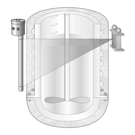
Page 125: Measuring Principle
For this reason, the radiometric measur- ing principle ensures high reliability and low maintenance. Source Detector Figure 1-4 Measuring Principle Uni-Probe LB 490 2 – 125 BERTHOLD TECHNOLOGIES GmbH & Co. KG... -
Page 126: Measuring Arrangements
The respective selections are made during the planning stage and must be observed during assembly and commissioning. The following scintillator types are available for the level gauge Uni-Probe LB 490: ID no. Size Description 38477-X1X, 47678-X1X, 500XX-X1X... - Page 127 - detector distance or for very thick vessel walls, one can choose an arrangement with rod source and rod detector to reduce the source activity (see Figure 1-7). In this Uni-Probe LB 490 2 – 127 BERTHOLD TECHNOLOGIES GmbH & Co. KG...
- Page 128 1 System Description Volume 2 case, the lengths of source and detector have to be adjusted to the size of the measuring range to be covered. The non-linearities obtained in the upper range of the characteristic curve are compensated for by means of a correction line adjusted to the measuring site and stored in the evaluation electronics.
- Page 129 The arrangement shown in Figure 1-9 is used for limit switches, e.g. to rule out overflowing when filling a vessel. Level Source Detector Detector signal Figure 1-9 Point source / Point detector arrangement for limit switches Uni-Probe LB 490 2 – 129 BERTHOLD TECHNOLOGIES GmbH & Co. KG...
-
Page 130: Technical Data
1 System Description Volume 2 Technical Data If you are working under different operating conditions, please con- tact BERTHOLD TECHNOLOGIES. for non ex-applications: Operating temperature range Operation: -40 … +50°C Storage: -50 … +55°C according to ATEX: Ex-protection DMT 02 ATEX E 132 II 2 GD Ex d IIB/IIC T6 (Gas Ex, Zone 1&2) - Page 131 250V / 5A or 24V 5A non-inductive Voltages larger than 150V must be grounded. Relay contacts are not protected by fuses. Relay 1: Error messages Uni-Probe LB 490 2 – 131 BERTHOLD TECHNOLOGIES GmbH & Co. KG...
- Page 132 1 System Description Volume 2 Relays 2 to 4 are also available for the following functions: – Min / Max – Halt – Detector temperature – Radiation interference 0.5 to 1.5mm Terminal cross-section: 3/4" NPT, 4 each, closed by dummy plugs Cable conduits: The cable cross-section is dependent on the cable screws used (see Cable cross-section...
-
Page 133: Detector Codes
38477-X7X 1500mm 47678-X7X 500XX-X7X 38477-X9X 2000mm 47678-X9X 500XX-X9X Super-Sens 53214-XXX 150x150mm Tower-Sens 50250-XXX 1000mm 50250-XXX 2000mm 50250-XXX 3000mm 50250-XXX 4000mm 50250-XXX 5000mm 50250-XXX 6000mm 50250-XXX 7000mm 50250-XXX 8000mm Uni-Probe LB 490 2 – 133 BERTHOLD TECHNOLOGIES GmbH & Co. KG... -
Page 134: Uni-Probe Lb 490 Nomenclature
1 System Description Volume 2 Uni-Probe LB 490 Nomenclature The first part of the ID no. describes the device version with respect to interfaces and explosion protection, the second part the variants of cooling, scintillator and mains supply. The type of com- munication and the signal output can also be identified via the LB numerical code. -
Page 135: Lb 490 Super-Sens Nomenclature
Volume 2 1 System Description LB 490 Super-Sens Nomenclature With the Uni-Probe LB 490 Super-Sens, the ID no. describes the device version, especially the last three digits. ID no. Communication Ex approvals Power supply Collimator Water cooling ® 53214-001 HART... -
Page 136: Lb 490 Tower-Sens Nomenclature
1 System Description Volume 2 LB 490 Tower-Sens Nomenclature With the Uni-Probe LB 490 Tower-Sens, the ID no. describes the device version, especially the last three digits. ID no. Communication Ex approvals Power supply Collimator Water cooling length ® 50250-001... - Page 137 1000mm with Fieldbus ™ 50250-036 FOUNDATION Ex-i/ATEX 2000mm with Fieldbus ™ 50250-038 FOUNDATION Ex-i/ATEX - 240V 1000mm with Fieldbus ™ 50250-040 FOUNDATION Ex-i/ATEX - 240V 2000mm with Fieldbus Uni-Probe LB 490 2 – 137 BERTHOLD TECHNOLOGIES GmbH & Co. KG...
- Page 138 1 System Description Volume 2 38477BA2B 2 – 138 25.5.09...
-
Page 139: Installation
Take the shielding out of the box just prior to installation. Up to that time, store the shielding with the radioactive source in a location that is guarded against unauthorized access, see chapter "2.1.4 Installation Sites" on page 2–142. Uni-Probe LB 490 2 – 139 BERTHOLD TECHNOLOGIES GmbH & Co. KG... - Page 140 If the Uni-Probe housing receives a mechan- ical blow, e.g. because it is dropped, then you have to return the Uni-Probe to BERTHOLD TECHNOLOGIES for inspection. Carefully install the mounting brackets and fixtures using the draw- ings of the shielding and taking into account the circumstances at the measuring site.
-
Page 141: Transport To The Installation Site
The operator has to take suitable provisions for temporary storage of sources at the place of installation between the period from source delivery to the start of the installation work. Uni-Probe LB 490 2 – 141 BERTHOLD TECHNOLOGIES GmbH & Co. KG... - Page 142 The exact position for your sys- tem parts is stated on the calculation documents and the technical information prepared by BERTHOLD TECHNOLOGIES. 2.1.5 Unpacking and Cleaning System Parts After unpacking, compare all parts with the packing list and check if the shipment is complete and shows any sign of damage.
-
Page 143: Source-Detector Arrangements
Volume 2 2 Installation Source-Detector Arrangements BERTHOLD TECHNOLOGIES offers a number of solutions for your applications. The schematic drawings below show examples of dif- ferent arrangements and refer you to the respective installation instructions. Since other arrangement than those shown here are possible, the installation of the detector side and the source side will be explained separately. - Page 144 2 Installation Volume 2 IMPORTANT If a suitable arrangement example should be missing for your spe- cial application, you will receive special documents in advance. Please contact us if you did not receive these documents. Please let us know the source number (you find it on the shielding) and we will provide you with the required information on this measuring point.
-
Page 145: Detector Protection
The ambient temperature must not exceed the values specified in the technical data (see Volume 2, "1.5 Technical Data", page 2– 130). The Uni-Probe LB 490 with water cooling jackets has to be used if temperatures exceeding 50° C are expected. The cooling water cycle has to remain in operation even when the instrument is turned off, if the temperature is likely to exceed 50°C. - Page 146 2 Installation Volume 2 2.3.2 Sun Protection If the Uni-Probe LB 490 is installed outdoors, it has to be protected against exposure to direct sunlight by a cover. Figure 2-1 Sun protection 2.3.3 Heavy-Duty Environments When selecting the installation site, keep in mind that the Uni-Probe LB 490 should not be affected by mechanical stress or heavy vibrations, in order not to restrict its service life.
-
Page 147: Detector Installation
100mm. The clamps have to be arranged so that no heat is transferred to the detector. Uni-Probe LB 490 2 – 147 BERTHOLD TECHNOLOGIES GmbH & Co. KG... - Page 148 2 Installation Volume 2 Point sources top fixing clamp 134 mm bottom fixing clamp » 100 mm Figure 2-2 Rod detector installation, example with point source Rod detector with detector shielding (collimator), with and with- out water cooling Due to the weight of the collimator, a mounting foot has to be used which will carry the detector with collimator.
- Page 149 The Tower-Sens detector supports a detector length of up to 8m. If needed, the Tower-Sens can be extended in several parts. The basic module for the Tower-Sens detector is always arranged at the Uni-Probe LB 490 2 – 149 BERTHOLD TECHNOLOGIES GmbH & Co. KG...
- Page 150 2 Installation Volume 2 bottom (connection and evaluation unit also at the bottom) (see Figure 2-5). End cap Source 1 Installation Fixing clamp base Source 2 Connection clamp Detector mounting base Electronics housing Figure 2-5 Tower-Sens arrangement, example with basic module and two extension modules Up to three extension modules with 2m length each can be put on top of the two possible basic modules of 1m or 2m length.
- Page 151 20cm and secure it with the fixing clamp. If this is the only extension module, you have to install the end cap first, see page 2–154. IMPORTANT Protect the module ends against humidity and dirt. Uni-Probe LB 490 2 – 151 BERTHOLD TECHNOLOGIES GmbH & Co. KG...
- Page 152 2 Installation Volume 2 End cap Connection clamp Fixing clamp Connection clamp Mounting plate Mounting bracket Extension module Basic module All dimensions in mm for 1m basic module (2m basic module) Figure 2-6 Structure of a Tower-Sens detector Take off the plastic protection cap from the extension module and then from the basic module.
- Page 153 Pull off the protective foils from the basic module and on the bottom of the extension module (Figure 2-8f). Place the guide sleeve on the basic module (Figure 2-9g). Uni-Probe LB 490 2 – 153 BERTHOLD TECHNOLOGIES GmbH & Co. KG...
- Page 154 2 Installation Volume 2 Figure 2-9 Installation of an extension module Open the fixing clamp of the extension module, push the exten- sion module into the guide sleeve and carefully push the mod- ule down until you reach the basic module (Figure 2-8h and i). ...
- Page 155 The combination of point detector and point source is typically used for two different types of application: for measurement of a limit level (Figure 2-11) or for continuous level measurement (Figure 2-12). Uni-Probe LB 490 2 – 155 BERTHOLD TECHNOLOGIES GmbH & Co. KG...
- Page 156 2 Installation Volume 2 Bracket provided by customer Uni-Probe Bracket provided by customer Point Detector Figure 2-11 Limit level measurement Installation kit Anti-tipping device provided with clamps, by customer optional Rod source shielding Bracket by cus- tomer Mounting base provided by customer Figure 2-12 Continuous level measurement As shown in Figure 2-12, the size of the measurement range for...
- Page 157 The radiation window of the Super-Sens detector has to be aligned toward the source. For more information on the fixtures please see the technical draw- ings in section 6.3.7 on page 2–267. Uni-Probe LB 490 2 – 157 BERTHOLD TECHNOLOGIES GmbH & Co. KG...
- Page 158 2 Installation Volume 2 Figure 2-13 Super-Sens with frontal irradiation IMPORTANT Please observe the alignment of the radiation window, see dimen- sional drawing of the detector (page 2–264). Side view Beam path View from above Figure 2-14 Detector installation 38477BA2B 2 –...
- Page 159 Figure 2-15 Super-Sens with radial (lateral) irradiation Anti-tipping device provided by customer Super-Sens Mounting base Rod source provided by shielding customer Mounting base provided by customer Figure 2-16 Super-Sens and rod source Uni-Probe LB 490 2 – 159 BERTHOLD TECHNOLOGIES GmbH & Co. KG...
-
Page 160: Mounting The Shielding
2 Installation Volume 2 Mounting the Shielding Shielding, source type, isotope and activity for each measurement configuration will be selected together with the customer to ensure compliance with the locally permitted dose rate limits. Co-60 or Cs-137 point sources are used which are tightly welded into a sturdy stainless steel capsule. - Page 161 (6) is firmly connected with a lever (4). The positions OPEN and CLOSED and the removal of the sources by unauthorized persons are secured by a padlock (3). Uni-Probe LB 490 2 – 161 BERTHOLD TECHNOLOGIES GmbH & Co. KG...
- Page 162 2 Installation Volume 2 1 Shielding 2 Source fixture 3 Padlock 4 Locking bolt 5 Point sources 6 Locking core 7 Beam path 8 Cover plate, front Figure 2-20 Cross-section drawing and photo of the point source shielding, beam path open Turning the lever (4) will also rotate the locking core and open the radiation exit channel towards the detector.
- Page 163 During installation, the shielding and thus the useful beam must be aligned such that they face the detector. Side view max. 45° Top view Figure 2-22 Point source shielding 45° Uni-Probe LB 490 2 – 163 BERTHOLD TECHNOLOGIES GmbH & Co. KG...
- Page 164 Install shielding 45° determine the background for rod detectors (see Volume 3, section 4.3.1 on page 3–351). Point source shielding Uni-Probe LB 490 Mounting Marking groove bracket Figure 2-23 Point source with rod detector The standard arrangement (Figure 2-23) shows the mounting posi- tion of the shielding with point source;...
- Page 165 2 base with an elongated hole allows the alignment of the source at the detector Figure 2-25 Installation proposal shielding; size B see section 6.6 on page 2–281 Uni-Probe LB 490 2 – 165 BERTHOLD TECHNOLOGIES GmbH & Co. KG...
- Page 166 2 Installation Volume 2 Eyebolts Direction of rotation for opening Order-related commission number Transportation safety device Do not remove the transpor- Designation of measuring tation safety device before system (option) completing the installation Type label of shielding with Borehole for lever model name and serial num- Source type label with information on source and...
- Page 167 Depending on the size of the measuring range, this arrangement can be realized with one or several detectors. Source 1 Uni-Probe LB 490 Marking grooves Source 2 Figure 2-27 Multi-source arrangement Uni-Probe LB 490 2 – 167 BERTHOLD TECHNOLOGIES GmbH & Co. KG...
- Page 168 2 Installation Volume 2 2.5.4 Rod Sources Increased radiation dose due to open beam path! A too high dose of radiation may be harmful to your health. A source may be transported only in its shielding. The shielding must be closed during transportation and installation. For rod sources, cylinder-shaped shieldings having the length of Rod source shielding the source are used which are provided with a radiation exit slit...
- Page 169 ("G") and the center of the detector are on a horizontal line, which defines the upper point of the measuring range (Max). Rod source Figure 2-30 Rod source arrangement, see also next table Uni-Probe LB 490 2 – 169 BERTHOLD TECHNOLOGIES GmbH & Co. KG...
- Page 170 2 Installation Volume 2 Diameter of shielding (in mm) G (in mm) The installation height of the supporting structure to be provided by the customer has to be measured using the dimensional drawings of the shielding. The size and stability of the supporting structure or another suit- able mounting device for the shielding has to match the size and total weight of the shielding.
- Page 171 As an option, rod source shieldings may be supplied with a pneu- Pneumatic actuator matic actuator. You find the technical data in section Uni-Probe LB 490 2 – 171 BERTHOLD TECHNOLOGIES GmbH & Co. KG...
- Page 172 2 Installation Volume 2 "6.8 Pneumatic for Rod and Point Source Shieldings" on page 2– 284. Risk of crushing! The cylinder rotates automatically! Fingers may get jammed on the strap or on the locking piece. Never change the factory-adjusted setting for attenuation of the pneumatic actuator.
- Page 173 This position can now be locked again with the padlock to prevent inadvertent closing of the beam path during operation. If locking with the lock should not be permitted, you may also fix the position with the supplied screw. Uni-Probe LB 490 2 – 173 BERTHOLD TECHNOLOGIES GmbH & Co. KG...
- Page 174 2 Installation Volume 2 2.5.6 Flange Shieldings in the Dip Tube Increased radiation dose due to open beam path! A too high dose of radiation may be harmful to your health. A source may be transported only in its shielding. The shielding must be closed during transportation and installation.
- Page 175 Uni-Probe LB 490 2 – 175 BERTHOLD TECHNOLOGIES GmbH & Co. KG...
- Page 176 2 Installation Volume 2 Shielding with source Pressure control Protection gas Vessel wall Detector Dip tube Protective tube Figure 2-35 Dip tube installation with rod source and rod detector One or up to five rod sources can be installed in a shielding, depending on type (see section 6.10 on page 2–286).
- Page 177 Operating a flange shielding with steel cable A steel cable for positioning of the rod source is supplied for each source. Uni-Probe LB 490 2 – 177 BERTHOLD TECHNOLOGIES GmbH & Co. KG...
- Page 178 2 Installation Volume 2 Caution: Source may fall into the dip tube. If the source drops into the dip tube during applications where the flange shielding has been installed onto the vessel from above, it can be recovered again only with a lot of work and under the super- vision of the Radiation Safety Officer.
- Page 179 The eyebolts can also be used as anti-tipping devices in the assembled state Engage latch in clutch Source locking Latch engaged in clutch mechanism Figure 2-37 Flange shielding with steel cable Uni-Probe LB 490 2 – 179 BERTHOLD TECHNOLOGIES GmbH & Co. KG...
- Page 180 2 Installation Volume 2 Pull the source back into the shielding using the steel cables or Move source again to the shielding the shaft core. position Fix the source with the clamping screw at the head piece. If the shielding contains several sources, then the order in which the sources are pulled back into the shielding is important to rule out that the cables get twisted: ...
- Page 181 Open the fixing screw at the head piece. Figure 2-41 Open fixing screw Open the source shielding. Figure 2-42 Open source shielding Push the shaft core in up to the limit stop. Uni-Probe LB 490 2 – 181 BERTHOLD TECHNOLOGIES GmbH & Co. KG...
- Page 182 2 Installation Volume 2 Figure 2-43 Push the shaft core in Fix the position with the fixing screw at the head piece. Attach the covering cap again. Secure the lock with a padlock or the safety screw. The source is now installed.
-
Page 183: Electrical Installation
For the supply line we recommend a backup fuse of 1A slow-blow. Backup fuse This fuse allows you to turn off the Uni-Probe, if necessary, and also to monitor the supply line to the Uni-Probe. Uni-Probe LB 490 2 – 183 BERTHOLD TECHNOLOGIES GmbH & Co. KG... -
Page 184: Conduits
3 Electrical Installation Volume 2 Conduits The Uni-Probe housing is provided with ¾" NPT conduits through which the electrical cables are installed according to regulations. Cable pipes or screwed cable glands can be screwed into the con- duits. They have to be licensed for the respective type of protection and have to be installed carefully in accordance with regulations! Make sure that the thread turns are clean and apply the supplied lubricant OKS 217 completely onto the NPT thread to be screwed... - Page 185 The tightening torques for the screwed cable glands supplied by BERTHOLD TECHNOLOGIES are listed in the technical documents in chapter 5, page 2–247. Armored cables Special screwed cable glands are needed for armored cables.
- Page 186 3 Electrical Installation Volume 2 If intrinsically safe signal lines are passed through areas with Installing intrinsically safe signal potentially explosive dust atmosphere or through zone 0, then they lines must be protected against electrostatic charge. 3.1.2 Please keep in mind for FM connection type A conduit seal has to be installed on each conduit used directly behind the Uni-Probe housing.
-
Page 187: Terminals
REL 1 Dig IN 1 Digital input 1 Error Halt REL 2 Alarm REL 3 Alarm REL 4 RS -232 interface Alarm (for software update) Figure 3-2 Terminals Uni-Probe LB 490 2 – 187 BERTHOLD TECHNOLOGIES GmbH & Co. KG... - Page 188 Max. cable length with Berthold cable # 32024: – 3300m at 120Ohm – 1600m at 250Ohm – 800m at 500Ohm We recommend using a screened cable, The BERTHOLD TECHNOLOGIES cable #32024 is shielded. 53 - 54 Not used 55 - 56 Not used 57 - 60 RS-485 for multi-detector mode.
-
Page 189: Switch Setting
Ω at the current output. ON OFF 120 Ohm / RS-485 4–20mA active passive with complete electronics Figure 3-3 Digital board Uni-Probe LB 490 2 – 189 BERTHOLD TECHNOLOGIES GmbH & Co. KG... - Page 190 3 Electrical Installation Volume 2 1. Capacitor-buffered real-time clock 2. Slide switch for current output With this slide switch you can choose whether power is gener- ated by the current output or supplied by an external source. Move slide switch to the left: current output is passive Move slide switch to the right: current output is active Versions with intrinsically safe current output may not be switched over, since the connected buffer amplifier serves as current output to the...
- Page 191 3 Electrical Installation Only a screened cable with twisted wires may be used as cable for Multi-detector mode wiring the RS485, e.g. the BERTHOLD TECHNOLOGIES cable, ID no. 32024. Connect the cable screen on both sides to the grounding bolt.
-
Page 192: Connecting The Uni-Probe
3 Electrical Installation Volume 2 Connecting the Uni-Probe If cables have already been connected to the Uni-Probe, then please keep in mind: Danger, electric shock! Open the housing cover of the Uni-Probe only after the device, pos- sibly connected relay contacts and all in- and outputs have been disconnected from power. - Page 193 "5 Screw Fittings and Accessories" on page 2–247. For conduits in the hazardous area: Seal the conduit seal behind the cable ducts using a suitable filling material. Uni-Probe LB 490 2 – 193 BERTHOLD TECHNOLOGIES GmbH & Co. KG...
- Page 194 3 Electrical Installation Volume 2 Do not remove the lubricant on the housing cover. If the thread is dry, you have to apply lubricant once more. Use only the lubricant OKS 217. Apply the lubricant evenly on the thread turns such that the thread turns are completely covered.
-
Page 195: Uni-Probe With Ex I Current Output
If 20m cable are not enough to reach the next distribution cabinet, you may use an intrinsically safe terminal box (ID no. 49546) to extend the cable. See also "3.5.3 Terminal Box" on page 2–198. Uni-Probe LB 490 2 – 195 BERTHOLD TECHNOLOGIES GmbH & Co. KG... - Page 196 3 Electrical Installation Volume 2 3.5.2 Uni-ProbeConnection Box Covering cap Isolating repeater Fuses for Isolating repeater (only for version LB 49x-11) Figure 3-6 Uni-Probe open The isolating repeater is mounted on the side in the connection box on a top hat rail. To ensure intrinsic safety, please do not: •...
- Page 197 The current output of the isolating repeater cannot be switched over between active and passive. The table on page 2–199 shows which type of isolating repeater is used in your device. Uni-Probe LB 490 2 – 197 BERTHOLD TECHNOLOGIES GmbH & Co. KG...
- Page 198 3 Electrical Installation Volume 2 3.5.3 Terminal Box Figure 3-8 Terminal box Use the terminal box (ID no. 49546) in order to extend the fac- tory-mounted 20m long current signal cable to the next distribu- tion point. The current output signal and the screen have to be looped via the terminal box.
- Page 199 -20°C … +50°C R.steel (passive) ID no. 47678-XXX IP66 T80°C Type 9164/13-22-09 LB 490 Super-Sens Ci=3.36nF; Li=13.65µH ID no. 53214-009 … -016 LB 490 Tower-Sens ID no. 50250-009 … -016 Uni-Probe LB 490 2 – 199 BERTHOLD TECHNOLOGIES GmbH & Co. KG...
- Page 200 3 Electrical Installation Volume 2 see chapter 1.5 Storage temperature Fuses for power supply 24 VAC/DC and 230 VAC: Fuses 2 ea. 1.25A breaking capacity 1500A Type Littelfuse Berthold ID no. 46719 Littelfuse order number: 215 1.25 Fuses for isolating repeater: Explosion hazard! If this fuse fails, the complete Uni-Probe has to be returned to the manufacturer for inspection, since the intrinsic safety is no longer...
- Page 201 Uni-Probe LB 490 2 – 201 BERTHOLD TECHNOLOGIES GmbH & Co. KG...
- Page 202 3 Electrical Installation Volume 2 I.S. Isolators mA - Isolating Repeater Type 9164 Intrinsically safe input (I.S.) or ● increased safety protection Ex e version Bi-directional HART ● transmission 4 ... 20 mA Suitable for 4-wire transmitter ● 1 channel ●...
- Page 203 ... 260 (AC-Impedance HART) (AC-Impedance HART) Communication signal HART transmission bi-directional; HART transmission bi-directional; 0,5 kHz ... 5 kHz 0,5 kHz ... 5 kHz Polarity reversal protection yes 10.11.2004 Uni-Probe LB 490 2 – 203 BERTHOLD TECHNOLOGIES GmbH & Co. KG...
- Page 204 3 Electrical Installation Volume 2 mA - Isolating Repeater Type 9164 Technical Data 9164/13-22-08 (I.S. Input) 9164/13-22-09 (Ex e Input) I.S. output Version passive (current sink up) passive (current sink up) Signal output 3.6 mA ... 21 mA with HART 3.6 mA ...
- Page 205 Dimension drawing (all dimensions in mm) - subject to alterations 0932E00 We reserve the right to make alterations to the technical data, weights, dimensions, designs and products available without notice. The illustrations cannot be considered binding. 10.11.2004 Uni-Probe LB 490 2 – 205 BERTHOLD TECHNOLOGIES GmbH & Co. KG...
-
Page 206: Uni-Probe With Signal Output Profibus Pa / Foundation
3 Electrical Installation Volume 2 Uni-Probe with Signal Output ™ Profibus PA / FOUNDATION Fieldbus (not intrinsically safe) The following special information is valid for the devices: • Profibus PA – LB 490 Uni-Probe ID no. 50035-XXX – LB 490 Super-Sens ID no. 53214-049 -056 …... - Page 207 This module is installed on the digital board of the Uni-Probe (see Figure 3-11). 1: + Terminals for Fieldbus communication 2: - Digital board Fieldbus module Figure 3-11 Digital board with field bus module Uni-Probe LB 490 2 – 207 BERTHOLD TECHNOLOGIES GmbH & Co. KG...
- Page 208 3 Electrical Installation Volume 2 3/4" NPT conduit Power supply 3/4" NPT conduit Equipotential bonding Fuses Power Digital Equipotential bonding supply board busbar provided by customer 3/4" NPT conduit RS -232 3/4" NPT conduit Figure 3-12 Connection box with field bus module ...
-
Page 209: Uni-Probe With Intrinsically Safe Signal Output Profibus Pa / Foundation
If 20 m cable are not enough to reach the next distribution cabinet, you may use an intrinsically safe terminal box (ID no. 49546) to extend the cable. See also "3.5.3 Terminal Box" on page 2–198. Uni-Probe LB 490 2 – 209 BERTHOLD TECHNOLOGIES GmbH & Co. KG... - Page 210 3 Electrical Installation Volume 2 Danger, electric shock! If the housing is open, you may get in contact with live parts if the power supply is turned on. Before turning on the power supply, carefully close the housing with the housing cover. Screw the housing cover completely onto the housing and pull it tight using a torque of 25Nm (reference value).
- Page 211 Uni-Probe is negligible. However, the cable data of the 20m firmly connected cable has to be taken into account for interconnection. The cable data of the 20m cable length are as follows: Capacity: 2.84nF Inductivity: 0.013mH Uni-Probe LB 490 2 – 211 BERTHOLD TECHNOLOGIES GmbH & Co. KG...
- Page 212 3 Electrical Installation Volume 2 The bus cable (ID no. 46413, UNITRONIC BUS PA FC (BU) 1x2xAWG18/1) supplied by Berthold Technologies has the following properties: Capacity (1kHz conductor/conductor) 50nF/km Capacity (1kHz conductor/screen) 92nF/km Inductivity (31.25kHz) 0.65mH/km … Ambient temperature range -20°C...
-
Page 213: Repair, Maintenance And Service
Spare parts for detectors used in hazardous areas may only be installed by BERTHOLD TECHNOLOGIES service personnel or by persons authorized by BERTHOLD TECHNOLOGIES. If this is not possible, the complete detector has to be replaced or returned to the manufacturer for repair. - Page 214 4 Repair, Maintenance and Service Volume 2 Danger of explosion when opening the housing in an explosive atmosphere! Please wait 30 minutes after you have turned off the power supply before you open the housing. The cooling-off time of 30 minutes ensures that possibly overheated components have enough time to cool off and cannot ignite the explosive atmosphere.
- Page 215 Uni-Probe housing cover. Please use the visual inspection schedule on page 2–216 and the plan for checking the connection room on page 2–217. Uni-Probe LB 490 2 – 215 BERTHOLD TECHNOLOGIES GmbH & Co. KG...
-
Page 216: Visual Inspection Of The Uni-Probe
4 Repair, Maintenance and Service Volume 2 Visual Inspection of the Uni-Probe If you answer one of the following questions with “No”, you have to record the action you have taken to remedy this deficiency in the last column. Make sure before you take the device into operation again that the provisions you have taken are correct by consulting with the person in charge of explosion protection. -
Page 217: Checking The Connection Box
Is the sealing inside the screw fitting OK? Is the O-ring for the sealing of the cover OK? (the O- ring is visisble from the outside at the edge of the cover) Uni-Probe LB 490 2 – 217 BERTHOLD TECHNOLOGIES GmbH & Co. KG... -
Page 218: Trouble Shooting
4 Repair, Maintenance and Service Volume 2 Trouble Shooting Problem Probable cause Potential solution No signal System out of work Check power supply check fuses; is LED 1 on the digital board flashing? Count rate too Shielding not or not cor- Check lock and secure it in rectly opened position OPEN... - Page 219 (software update) – LED off: CPU malfunction, or no power supply 2. Communication LEDs ® If a communication via fieldbus or HART exists, both LEDs (TxD, RxD) are flashing. Uni-Probe LB 490 2 – 219 BERTHOLD TECHNOLOGIES GmbH & Co. KG...
-
Page 220: Replacing The Complete Uni-Probe
4 Repair, Maintenance and Service Volume 2 Replacing the Complete Uni-Probe Devices that are used in non-hazardous areas may not be used any more in hazardous areas. Intrinsically safe devices whose intrinsically safe signals are con- nected to non-intrinsically safe electric circuits may also not be connected to intrinsically safe electric circuits any more. - Page 221 Volume 2 4 Repair, Maintenance and Service Carry out a new empty calibration (see the respective software description). Then the Uni-Probe is operational again. Uni-Probe LB 490 2 – 221 BERTHOLD TECHNOLOGIES GmbH & Co. KG...
-
Page 222: Replacing The Electronics Module
Spare parts for detectors used in hazardous areas may only be installed by BERTHOLD TECHNOLOGIES service personnel or by persons authorized by BERTHOLD TECHNOLOGIES. If this is not possible, the complete detector has to be replaced or returned to the manufacturer for repair. - Page 223 You find the device numbers on white labels with a two, three or four-digit number. The inscription reads: “Dev. ID XXXX”. Establish the power supply to the Uni-Probe again. Uni-Probe LB 490 2 – 223 BERTHOLD TECHNOLOGIES GmbH & Co. KG...
- Page 224 4 Repair, Maintenance and Service Volume 2 Set the software parameters again using the list you have noted down earlier. See also Volume 3 on page 3–295. Separate User’s Manuals are available for user interfaces such ™ as SIMATIC PDM or FOUNDATION Fieldbus.
-
Page 225: Replacing The Crystal-Multiplier Assembly (For Point Detector)
Spare parts for detectors used in hazardous areas may only be installed by BERTHOLD TECHNOLOGIES service personnel or by persons authorized by BERTHOLD TECHNOLOGIES. If this is not possible, the complete detector has to be replaced or returned to the manufacturer for repair. - Page 226 4 Repair, Maintenance and Service Volume 2 IMPORTANT Replacement of the multiplier requires a new setting of detector code and HV parameters. Please see Volume 2, "1.6 Detector Codes", page 2–133, and Volume 3, "2.38 HV S ", page 3– ETTINGS 334.
-
Page 227: Replacing The Multiplier (For Rod Detector)
Spare parts for detectors used in hazardous areas may only be installed by BERTHOLD TECHNOLOGIES service personnel or by persons authorized by BERTHOLD TECHNOLOGIES. If this is not possible, the complete detector has to be replaced or returned to the manufacturer for repair. -
Page 228: Fieldbus (Not Intrinsically Safe)
4 Repair, Maintenance and Service Volume 2 Check the level indication empty and full . If you detect any deviations, please carry out a new calibration, see Volume 3, "4 Calibration", on page 3–341. Separate User’s Manuals are available for user interfaces such ™... -
Page 229: Replacing The Plastic Scintillator
Spare parts for detectors used in hazardous areas may only be installed by BERTHOLD TECHNOLOGIES service personnel or by persons authorized by BERTHOLD TECHNOLOGIES. If this is not possible, the complete detector has to be replaced or returned to the manufacturer for repair. - Page 230 4 Repair, Maintenance and Service Volume 2 dow (Berthold ID no. 18844) to establish the optical connection between both parts. Install the electronics module in the Uni-Probe as described on page 2–223. Check the level indication empty and full . If you detect any deviations, please carry out a new calibration, see Volume 3, "4 Calibration", on page 3–341.
-
Page 231: Replacing The Digital Board
Spare parts for detectors used in hazardous areas may only be installed by BERTHOLD TECHNOLOGIES service personnel or by persons authorized by BERTHOLD TECHNOLOGIES. If this is not possible, the complete detector has to be replaced or returned to the manufacturer for repair. - Page 232 4 Repair, Maintenance and Service Volume 2 Dismantled digital board Figure 4-6 Digital board There are three versions of digital boards. The current version is Digital board versions described in detail in this User's Manual and is called digital board The digital boards can be exchanged against each other;...
- Page 233 Uni-Probe housing. IMPORTANT After installation of a new software, carry out a “Factory Reset” (Volume 3, "7.4 Reset", on page 3–397); otherwise a correct func- tion cannot be ensured. Uni-Probe LB 490 2 – 233 BERTHOLD TECHNOLOGIES GmbH & Co. KG...
-
Page 234: Replacing The Power Supply Unit
Spare parts for detectors used in hazardous areas may only be installed by BERTHOLD TECHNOLOGIES service personnel or by persons authorized by BERTHOLD TECHNOLOGIES. If this is not possible, the complete detector has to be replaced or returned to the manufacturer for repair. - Page 235 Install the new digital board in reverse order. Install the electronics module in the Uni-Probe as described on page 2–223. This completes the replacement of the power supply. Uni-Probe LB 490 2 – 235 BERTHOLD TECHNOLOGIES GmbH & Co. KG...
-
Page 236: Replacing Fuses
4 Repair, Maintenance and Service Volume 2 4.12 Replacing Fuses Two fuses (16) are located on the power supply board (14). Position Power supply board 24V AC/DC Power supply board 90 - 240V AC/DC Figure 4-8 Position of power supply board and fuses in the device Type of fuse: Berthold part #46719. -
Page 237: Updating The Embedded Software In The Uni-Probe
The cooling-off time of 30 minutes ensures that possibly overheated components have enough time to cool off and cannot ignite the explosive atmosphere. Unscrew the housing cover (M32 screw wrench). Uni-Probe LB 490 2 – 237 BERTHOLD TECHNOLOGIES GmbH & Co. KG... - Page 238 4 Repair, Maintenance and Service Volume 2 Connect the RS-232 interface of your PC via the null modem cable to the RS-232 interface (17) of the Uni-Probe. Figure 4-9 Position of RS-232 interface in the open device Danger, electric shock! The update has to be carried out with open housing cover.
- Page 239 Select the respective update file. Click on FILE LOAD BINARY FILE Select in the directory the update file (in our example LB490.RUN Click on to start the update. PROGRAM Uni-Probe LB 490 2 – 239 BERTHOLD TECHNOLOGIES GmbH & Co. KG...
- Page 240 4 Repair, Maintenance and Service Volume 2 The flash memory is checked and this check shows that the flash memory is not empty. Confirm the update by clicking on . The ERASE AND PROGRAM download is now carried out. This may take several minutes. The progress bar shows that the Uni-Probe programming is running.
- Page 241 See also Volume 3 on page 3–295. Separate User’s Manuals are available for user interfaces such ™ as SIMATIC PDM or FOUNDATION Fieldbus. The Uni-Probe is again ready for use. Uni-Probe LB 490 2 – 241 BERTHOLD TECHNOLOGIES GmbH & Co. KG...
-
Page 242: Check Detector
4 Repair, Maintenance and Service Volume 2 4.14 Check Detector Scintillation counters do not include any wearing parts and their service life is not limited, provided they are used under normal operating conditions. Malfunctions in the scintillation detector can only be caused by excessive mechanical or thermal stress. See also Volume 2, sections 2.5 and 7. - Page 243 While you are doing this, make sure that the multiplier is not exposed to bright sunlight. Magnetic shielding (Mu metal) Crystal Multiplier Optical connection Figure 4-12 Crystal-multiplier assembly Uni-Probe LB 490 2 – 243 BERTHOLD TECHNOLOGIES GmbH & Co. KG...
- Page 244 4 Repair, Maintenance and Service Volume 2 The crystal must be perfectly clear inside and not show any cracks or dull areas. The normal coloring is slightly greenish. A yellowish to brownish coloring is a sign of thermal overload and indicates that the crystal must be replaced.
-
Page 245: Customer Service
– Measuring device, e.g. level, rod source with rod detector • Parameter listing • Source number and / or Berthold commission number • Contact person and phone number Uni-Probe LB 490 2 – 245 BERTHOLD TECHNOLOGIES GmbH & Co. KG... -
Page 246: Returning Repairs
Your order number (if necessary) • Preferred mode of transportation (if necessary) • Customs value (for cross-border shipment) BERTHOLD TECHNOLOGIES delivery address: BERTHOLD TECHNOLOGIES GmbH & Co. KG Service Department Calmbacher Str. 22 D-75323 Bad Wildbad 38477BA2B 2 – 246... -
Page 247: Screw Fittings And Accessories
Three sealing kits enclosed: 3–8mm, 7–12mm, 11.5–15mm To obtain better sealing capabilities against penetrating liquid, the Sealing against humidity screw threads of the screwed cable glands, the adapter and the Uni-Probe LB 490 2 – 247 BERTHOLD TECHNOLOGIES GmbH & Co. KG... - Page 248 5 Screw Fittings and Accessories Volume 2 dummy plugs have to be greased with the lubricant OKS 217. Apply the lubricant evenly on the threads such that the threads are completely covered. Remove excess lubricant. 5.1.2 Nickel-Plated Screwed Cable Gland Brass This type of screwed cable glands are suitable for zones 1 and 2.
-
Page 249: Atex-Adapter (Ex D Iic) For Screwed Cable Glands
Corrosion protection and sealing for NPT thread Adapter and dummy plug include NPT external screw threads. NPT screw threads must NOT be sealed with Teflon tape. For NPT screw Uni-Probe LB 490 2 – 249 BERTHOLD TECHNOLOGIES GmbH & Co. KG... - Page 250 5 Screw Fittings and Accessories Volume 2 threads you have to use the lubricant OKS 217 as corrosion protec- tion, which at the same time has a sealing effect. A sufficient amount of lubricant OKS 217 is enclosed with each Uni-Probe. Apply the lubricant evenly on the threads such that the threads are completely covered.
-
Page 251: Technical Drawings
Technical Drawings Point Detector Type Crystal Collimator Weight (kg) Total length 38477-X10 radial 22.5 without water cooling 38477-X20 axial 50/50 38477-X11 radial with water cooling 38477-X21 axial 24.5 Uni-Probe LB 490 2 – 251 BERTHOLD TECHNOLOGIES GmbH & Co. KG... - Page 252 6 Technical Drawings Volume 2 6.1.1 Point Detector Mounting Clamps 76 mm (without water cooling) 90 mm (with water cooling, plastic ring not needed) Mounting clamps for ID no. Point detector without water cooling 39246 Point detector with water cooling 39247 38477BA2B 2 –...
- Page 253 Volume 2 6 Technical Drawings 6.1.2 Holding Device Mounted on Detector 6.1.3 Installation on vessel Uni-Probe LB 490 2 – 253 BERTHOLD TECHNOLOGIES GmbH & Co. KG...
-
Page 254: Rod Detector
6 Technical Drawings Volume 2 Rod Detector 38477BA2B 2 – 254 25.5.09... - Page 255 Rod Detector without Water Cooling Type Sensitive scintillator Weight length (mm) (mm) (mm) (kg) (mm) 38477-X30 14,5 38477-X50 1000 1404 1174 38477-X70 1500 1904 1674 38477-X90 2000 2404 2174 26.5 Uni-Probe LB 490 2 – 255 BERTHOLD TECHNOLOGIES GmbH & Co. KG...
- Page 256 6 Technical Drawings Volume 2 6.2.2 Rod Detector with Water Cooling Type Sensitive scintilla- Weight Weight tor length (mm) (mm) (mm) without water with water (mm) (kg) (kg) 38477-X31 18.5 19.5 38477-X51 1000 1404 1174 28,5 38477-X71 1500 1904 1674 38477-X91 2000 2404...
- Page 257 Sensitive length Marking Position of clamps EPDM profile A set of clamps (2 each) ID no. (mm) For Uni-Probe without water cooling 39983 For Uni-Probe with water cooling 31347 Uni-Probe LB 490 2 – 257 BERTHOLD TECHNOLOGIES GmbH & Co. KG...
- Page 258 6 Technical Drawings Volume 2 6.2.4 Shielding for Rod Detector without Water Cooling Mounting foot top/bottom Ø 11 Ø 75 Length scintillator Length rod detector Length shielding Dismantling ID no. Weight (mm) (mm) (mm) from above approx. (kg) 1000 42744-050 1000 1400 1120...
- Page 259 (mm) from above approx. (kg) 1000 42131-050 1000 1400 1120 1155 1090 1500 42131-100 1500 1900 1620 1655 1590 2100 42131-150 2000 2400 2120 2155 2090 2600 42131-200 Uni-Probe LB 490 2 – 259 BERTHOLD TECHNOLOGIES GmbH & Co. KG...
- Page 260 6 Technical Drawings Volume 2 6.2.6 Collimator Details for Rod Detectors Cross-section View from above View from the front Collimator alignment to Clamping screw for Lead filling source rod detector 6.2.7 Installation Instructions for Collimator with Rod Detector We recommend using an installation/ deinstallation room for swiveling out Boreholes for installation of of the mounting foot...
- Page 261 Distance to the vessel wall approx. 100mm Mounting platform Installed by the installation con- tractor, e.g. welded to the vessel or the supporting structure. Uni-Probe LB 490 2 – 261 BERTHOLD TECHNOLOGIES GmbH & Co. KG...
- Page 262 6 Technical Drawings Volume 2 6.2.9 Terminal Position for Rod Detector (with and without Water Cooling) 2000 All dimensions in mm 1500 1000 6.2.10 Position of the Fixtures for Rod Detector Shieldings (with and without Water Cooling) 2000 All dimensions in mm 1500 1000 38477BA2B...
- Page 263 6 Technical Drawings 6.2.11 Terminal Position for Multi-detector Arrangement All dimensions in mm 100% 6.2.12 Position of the Fixture for Multi-detector Arrangement with Collimators All dimensions in mm Uni-Probe LB 490 2 – 263 BERTHOLD TECHNOLOGIES GmbH & Co. KG...
-
Page 264: Super-Sens
6 Technical Drawings Volume 2 Super-Sens 6.3.1 Super-Sens with Frontal Irradiation Weight approx. 60kg 6.3.2 Super-Sens with Frontal Irradiation and Water Cooling Weight approx. 65kg Connection seal for water cooling: ø 10mm /R ¼" 38477BA2B 2 – 264 25.5.09... - Page 265 Weight approx. 45kg 6.3.4 Super-Sens with Radial Irradiation and Water Cooling Radial heat protection Radial heat protection Weight approx. 50kg Connection seal for water cooling: ø 10mm /R ¼" Uni-Probe LB 490 2 – 265 BERTHOLD TECHNOLOGIES GmbH & Co. KG...
- Page 266 6 Technical Drawings Volume 2 6.3.5 Water Cooling with Horizontal Installation Outlet Inlet With horizontal installation of the detector, the water inlet is con- nected directly to the end of the pipeline on the side of the cable entries. 6.3.6 Water Cooling with Vertical Installation Outlet Inlet...
- Page 267 Side view Top view Radiation window Section for radiation window Radiation path Bracket Ø18 With installed Super-Sens detector Radiation window Section for radiation window Radiation path Bracket Uni-Probe LB 490 2 – 267 BERTHOLD TECHNOLOGIES GmbH & Co. KG...
-
Page 268: Tower-Sens
6 Technical Drawings Volume 2 Tower-Sens 6.4.1 Basic Module without Water Cooling (0.59) (4.33) (6.02) (5.12) (8.00) (8.46) Mounting plate 100...170 (4...6.7) Clamp position Mounting plate 180° 135° Dimensions in mm (inch) Housing material stainless steel 1.4301 45° 0° (2.91) 4 cable conduits 3/4NPT internal screw threads (4.33) Type... - Page 269 4 cable conduits 3/4NPT internal screw threads (4.33) Type Sensitive length L1 Length L Length L2 Weight approx. (mm) (mm) (mm) (kg) 1000 mm 1385 2000 mm 1990 2385 1833 Uni-Probe LB 490 2 – 269 BERTHOLD TECHNOLOGIES GmbH & Co. KG...
- Page 270 6 Technical Drawings Volume 2 6.4.3 Extension Module without Water Cooling Sealing 100...400 (4...16) Window Clamp position Dimensions in mm (inch) EPDM profile Type Sensitive length L1 Length L Weight approx. (mm) (mm) (kg) 2000 mm 2000 2021 38477BA2B 2 – 270 25.5.09...
- Page 271 Sealing (3.34) (72.9) (3.34) Window Clamp position Dimensions in mm (inch) EPDM profile Type Sensitive length L1 Length L Weight approx. (mm) (mm) (kg) 2000 mm 2000 2021 Uni-Probe LB 490 2 – 271 BERTHOLD TECHNOLOGIES GmbH & Co. KG...
- Page 272 6 Technical Drawings Volume 2 6.4.5 Installation Proposal for Tower-Sens Base The mounting base has to be provided by the customer. ~200 ~110 (~7.9) (~4.3) (8.66) Ø18 (Ø0.71) Ø112 (Ø4.41) Dimensions in mm (inch) (5.67) 38477BA2B 2 – 272 25.5.09...
-
Page 273: Point Source Shielding Lb 744X
LB 7440 DE CR LB 7442 F CR LB 7442 D CR ND 200, PN 6 LB 7442 FE CR LB 7442 DE CR ND 200, LB 7444 CR PN 6 Uni-Probe LB 490 2 – 273 BERTHOLD TECHNOLOGIES GmbH & Co. KG... - Page 274 6 Technical Drawings Volume 2 6.5.1 Installation Proposal for Point Source Shielding LB 744X The shielding vessel is consisting of a stable casting cabinet filled with lead. A rotary shutter is installed to close the radiation exit channel. Operation is made from behind by a T-handle, which is secured by a padlock in open as well as in closed position.
- Page 275 2 proximity switches for intrinsically safe supply ID no. Description 36119 Pneumatic actuator with limit switch IP 65 80919 Pneumatic actuator with limit switch Ex de IIC T6 Uni-Probe LB 490 2 – 275 BERTHOLD TECHNOLOGIES GmbH & Co. KG...
- Page 276 6 Technical Drawings Volume 2 Parts of the pneumatic actuator Return spring (FAIL-SAFE) with Pneumatic actuator pneumatic actuator Adjustable cams Square neck for position indication or possible hand actuating Limit switch for position OPEN Point source Limit switch for position shielding LB 744X CLOSED Cable gland...
- Page 277 Move revolving wings to the opposite stop position. Com- pressed air is needed for single-acting swivel drives with spring lock unit. Proceed accordingly with the second trip cam. Uni-Probe LB 490 2 – 277 BERTHOLD TECHNOLOGIES GmbH & Co. KG...
- Page 278 6 Technical Drawings Volume 2 Technical Specification / Electrical Wiring … 2 micro push-buttons BARTEC 07-1501-6120-63 (closer) for drive size 02/03 BARTEC 07-1501-6130-63 (changer) for drive size 05-14 Volt Load (A) Resistor inductive (max.) up to 12 up to 24 up to 48 0.06 up to 250...
- Page 279 Ø50 Installation according to factory norm After connecting, tighten the stuffing box fitting. IMPORTANT Make sure that the cover sealing is inserted in its groove! Uni-Probe LB 490 2 – 279 BERTHOLD TECHNOLOGIES GmbH & Co. KG...
- Page 280 6 Technical Drawings Volume 2 Slightly grease the housing cover in the shaft duct with MoS grease, attach the cover and tighten the cover screws. Correction of the switching points Direct installation for drives with pre-assembled Unscrew the cover of the supplied limit-switch box and pull it limit-switch box off, as shown in the illustration, while pushing down the limit-switch shaft.
-
Page 281: Point Source Shielding For Rod Detectors
Volume 2 6 Technical Drawings Point Source Shielding for Rod Detectors Point source Radiation exit Padlock Position Open Position Closed Type plate Type Weight (kg) Uni-Probe LB 490 2 – 281 BERTHOLD TECHNOLOGIES GmbH & Co. KG... -
Page 282: Rod Source Shielding
6 Technical Drawings Volume 2 Rod Source Shielding Point source Radiation exit Padlock Position Open Position Closed Type plate Type approx. Kg/m approx. 204.5 11.5 224.5 11.5 11.5 222. 38477BA2B 2 – 282 25.5.09... - Page 283 The required individual types of shieldings are labeled with Roman numbers. Shielding ∅ Drawing no. 21157.000-000 21159.000-000 21160.000-000 21161.000-000 Uni-Probe LB 490 2 – 283 BERTHOLD TECHNOLOGIES GmbH & Co. KG...
-
Page 284: Pneumatic For Rod And Point Source Shieldings
6 Technical Drawings Volume 2 Pneumatic for Rod and Point Source Shieldings Pneumatic drive for point source shieldings with spring reset: 40085 Type 100 40084 Type 100, limit switch (Ex) 41689 Type 150 41690 Type 150, limit switch (Ex) 412681 Type 200 41691 Type 200, limit switch (Ex) -
Page 285: Pneumatic, Design And Electrical Data For Limit Switch
Position marked by a milled-in red line 0.06 0.06 0.25 0.03 0.25 0,05 0.025 Return spring (FAIL-SAFE) with pneumatic actuator Shielding type 80 … 270 Uni-Probe LB 490 2 – 285 BERTHOLD TECHNOLOGIES GmbH & Co. KG... -
Page 286: Shielding For Rod Source On Dip Tube
6 Technical Drawings Volume 2 6.10 Shielding for Rod Source on Dip Tube 38477BA2B 2 – 286 25.5.09... -
Page 287: Flange Adapter For Rod Source Shieldings
Volume 2 6 Technical Drawings 6.11 Flange Adapter for Rod Source Shield- ings Uni-Probe LB 490 2 – 287 BERTHOLD TECHNOLOGIES GmbH & Co. KG... - Page 288 6 Technical Drawings Volume 2 38477BA2B 2 – 288 25.5.09...
-
Page 289: Cooling Water Curves
Ambient temperature in ºC Rod Detector Cooling water curves for rod detector 500 mm Cooling water curves for rod detector 500 mm Cooling water input temperature Ambient temperature in ºC Uni-Probe LB 490 2 – 289 BERTHOLD TECHNOLOGIES GmbH & Co. KG... - Page 290 7 Cooling Water Curves Volume 2 Cooling water curves for rod detector 1000 mm Cooling water curves for rod detector 1000 mm Cooling water input temperature Ambient temperature in ºC Cooling water curves for rod detector 1500 mm Cooling water curves for rod detector 1500 mm Cooling water input temperature Ambient temperature in ºC Cooling water curves...
-
Page 291: Super-Sens
Ambient temperature in ºC Tower-Sens Cooling water curves for Tower-Sens detector 40 °C Cooling water input temperature Cooling water input temperature 30 °C 20 °C 10 °C Ambient temperature in ºC Uni-Probe LB 490 2 – 291 BERTHOLD TECHNOLOGIES GmbH & Co. KG... - Page 292 7 Cooling Water Curves Volume 2 38477BA2B 2 – 292 25.5.09...
- Page 293 Volume 2 Notes: Uni-Probe LB 490 2 – 293 BERTHOLD TECHNOLOGIES GmbH & Co. KG...
- Page 294 Subject to change in the course of further technical development. © BERTHOLD TECHNOLOGIES GmbH & Co. KG 2009 Language: English Printed in Germany 05/2009 Rev. no.: 05 BERTHOLD TECHNOLOGIES GmbH & Co. KG Calmbacher Str. 22 D-75323 Bad Wildbad Germany www.Berthold.com...
- Page 295 Volume 3 ® HART Communicator User Interface...
-
Page 296: Volume 3
Volume 3 38477BA2B 3 – 296 25.5.09... -
Page 297: Hart
® The Level Gauge Uni-Probe LB 490 is compatible with the HART Communicator made by Emerson Process (HART = Highway ® Addressable Remote Transducer). Other HART compatible com- ®... -
Page 298: Working With The Hart Communicator
® 1 General Information on the HART Communicator Volume 3 The Communicator may be turned off or disconnected only upon completion of a possible parameter change with the Uni-Probe. ® Working with the HART Communicator Operation of the Communicator is quite simple: •... -
Page 299: Menu Structure
Uni-Probe. The following sections require that you: • know how to operate the Communicator • have read and understood Volume 2 ("Uni-Probe Installation") of this User’s Manual. Uni-Probe LB 490 3 – 299 BERTHOLD TECHNOLOGIES GmbH & Co. KG... -
Page 300: Menu Overview
Menu Structure Volume 3 Menu Overview ISPLAY ROBE EVIEW LEVEL PROBE NO DEVICE TYPE CPS AVERAGE DISTRIBUTOR CPS LIVE HV READING MANUFACTURER CURRENT HB MODE DEVICE ID PROBE RAW DATA TEMPERATURE SENSOR SERIAL NO OF PROBES page 3–303 DESCRIPTOR page 3–304 MESSAGE ARAMETERS ROCESS... - Page 301 1-2 P ALIBRATION ALIBRATION OINT URVE POINT CALIBRATION SET BACKGROUND CALIBRATION OF CAL POINTS INPUT OUTPUT POINT SHOW CAL CURVE POINT ETUP page 3–321 & & SAVE LOAD CURVE SORT CHECK CURVE Continued CONFIGURATION on page 3–300 page 3–321 page 3–323 PASSWORD NPUT UTPUT...
-
Page 302: Start Menu
Menu Structure Volume 3 Start Menu The Start menu is the first and highest level for communication with the Uni-Probe. From the Start menu you have access to all other menu items. The Start menu appears when you ® • switch on the connected HART Communicator or •... -
Page 303: Live Display
Shows the live current output in mA. ROBE Leads to the raw data of the detector. In case of multi-detector operation the raw data of the Auxiliary Units are also displayed. Uni-Probe LB 490 3 – 303 BERTHOLD TECHNOLOGIES GmbH & Co. KG... -
Page 304: Probe Raw Data
Menu Structure Volume 3 ROBE ROBE Select the detector number whose raw data you want to view. 0 is the number for the Main Unit 1, 2, … are numbers of available Auxiliary Units ULSE Shows the live count rate of the selected probe. 3 HV R EADING Shows the live high voltage (HV) of the selected probe. -
Page 305: View Parameter
Level value of the upper range limit (20 mA) for the current output. ANGE Level value of the lower range limit (4 mA) for the current output. URVE Shows the calibration points. Uni-Probe LB 490 3 – 305 BERTHOLD TECHNOLOGIES GmbH & Co. KG... -
Page 306: Show Cal . Curve
Menu Structure Volume 3 URVE ALIBRATION OINT Shows the calibration points. The background and all calibration points may be viewed one after another. For one and two-point calibration the type of calibration is displayed as well (linear/exponential). • Select Cal. Point: number of calibration point. •... -
Page 307: Status Control
EVIEW This menu item includes additional information. The use and mean- ing of some of the information is up to the operator, whereas others are determined by the BERTHOLD TECHNOLOGIES. Uni-Probe LB 490 3 – 307 BERTHOLD TECHNOLOGIES GmbH & Co. KG... -
Page 308: Show Error Log
Menu Structure Volume 3 2.10 RROR The following example shows an error list containing two HV- errors: • Error Num: Consecutive error number • Probe ID: Number of the Uni-Probe which has indicated this error. Only relevant for multi-detector operation. •... -
Page 309: Review
Device identification number. It shows the specific HART ID num- ber. This information is set up by BERTHOLD TECHNOLOGIES and cannot be changed by the operator. If the device is used as an auxiliary unit, it is the address number to communicate with the main unit. - Page 310 Menu Structure Volume 3 NIVERSAL REV ® Shows the revision of the specific universal HART command set. ® For the Uni-Probe you need the Universal Commands for HART ® or higher. This means, that the HART Communicator, e.g. by Emerson Process Model 275, has to be equipped at least with the firmware 2.5 or the newer model 375 has to be used.
-
Page 311: Access To Setup
Depending on the password, other information may be displayed here, such as: • CCESS • & C ONFIGURATION ALIBRATION • ONFIGURATION • NTER ASSWORD Leads to the password entry to gain access to the respective level(s). Uni-Probe LB 490 3 – 311 BERTHOLD TECHNOLOGIES GmbH & Co. KG... -
Page 312: Enter Password
Menu Structure Volume 3 2.13 NTER ASSWORD Up to 3 different passwords may be defined. Passwords may even be identical; in this case, they open several levels at the same time. The standard password for passwords 1, 2 and 3 is UNI-PROBE. We recommend changing the standard password fairly soon. -
Page 313: Setup
Changes the password. How to define the password is described in detail on page 3–369. 2.15 ONFIGURATION ENERAL Shows the general parameters. YSTEM ARAMETER Shows the system parameters. EASURE ARAMETER Shows the measurement parameters. Uni-Probe LB 490 3 – 313 BERTHOLD TECHNOLOGIES GmbH & Co. KG... -
Page 314: General Data
(starting with software revision 12) Standard input is the Device ID. SSEMBLY (starting with software revision 12) ISTRIBUTOR BERTHOLD TECHNOLOGIES is entered as Distributor. This term is fixed and cannot be changed by the operator. 38477BA2B 3 – 314 25.5.09... -
Page 315: System Parameter
If the error relay is not used, the operator cannot be warned if minor errors do occur. Uni-Probe LB 490 3 – 315 BERTHOLD TECHNOLOGIES GmbH & Co. KG... -
Page 316: Measure Parameter
Menu Structure Volume 3 2.18 EASURE ARAMETER AMPING Time constant and damping mode. NTERFERENCE Function for the detection of radiation interference due to, for example: • welding seam tests • other sources in the vicinity of the detector. The use of the Interference function makes sense only if you expect any unpredictable radiation interference. -
Page 317: Damping Data
1 x T = single measurement time; Standard: 20 s 3 x T = virtually corresponds to the end value Figure 2-1 Time constant The time constant corresponds in its function to an RC element. Uni-Probe LB 490 3 – 317 BERTHOLD TECHNOLOGIES GmbH & Co. KG... - Page 318 Menu Structure Volume 3 t = R x C Figure 2-2 RC element APID WITCH • No: without rapid switchover • Yes: with rapid switchover 2.19.1 Function Rapid Switchover The use of the function R is recommended only for APID WITCH special applications where the output signal has to adapt rapidly to the new value, e.g.
-
Page 319: Rad . Interference
If interference radiation is detected, then the measurement stops for the duration of the delay time. You have to enter a value in sec- onds. For detailed information on radiation interference detection please see page 3–383. Uni-Probe LB 490 3 – 319 BERTHOLD TECHNOLOGIES GmbH & Co. KG... -
Page 320: Pulse Rate Limits
Menu Structure Volume 3 2.21 ULSE IMITS IMIT Upper pulse rate limit Enter “0” to disable this function. This function is enabled only for special applications. Enter a value unequal to zero to enable the upper threshold. If the current pulse rate exceeds the upper threshold, the measurement is halted until the pulse rate has dropped below this threshold again. -
Page 321: Calibration I/O
& L URVE This function allows you to save the existing calibration data set to a separate memory of the Uni-Probe and to restore it again, if nec- essary. Uni-Probe LB 490 3 – 321 BERTHOLD TECHNOLOGIES GmbH & Co. KG... - Page 322 Menu Structure Volume 3 & L 2.24 URVE Saves the existing calibration data set to a separate memory. This data set can be restored any time with LOAD Loads the saved calibration data set and overwrites the existing calibration. You are prompted to confirm this action. 38477BA2B 3 –...
-
Page 323: Point Curve
Always select this function at the end of the calibration process to ensure that your calibration data is plausible. The calibration sequence is described in detail in Volume 3, section Uni-Probe LB 490 3 – 323 BERTHOLD TECHNOLOGIES GmbH & Co. KG... -
Page 324: Multi Point Curve
Menu Structure Volume 3 2.26 ULTI OINT URVE If you have entered 3 or more calibration points in the previous window Calibration, the window depicted to the left will appear. ACKGROUND Setting the background rate (see also Volume 3, section 4). NTER Enter the values for all calibration points. -
Page 325: Cal . Point
Enable the respective digital input, provided you want to use it. The functions of the digital inputs are explained starting on page 2– 187. ONFIG Shows the parameters for the relay outputs. Uni-Probe LB 490 3 – 325 BERTHOLD TECHNOLOGIES GmbH & Co. KG... -
Page 326: Current / Output
Menu Structure Volume 3 2.29 URRENT UTPUT ANGE Upper limit value Enter the level for 20mA current output. Standard: 100% In case of level values exceeding the upper limit value, the current output can follow up to max. 20.8mA. This simplifies the identifica- tion whether the measured value is greater than 100%. -
Page 327: Digital Out Co Nfig
If the level exceeds 60%, the relay is set to the alarm status. If the level then drops again below 55%, the relay is set back to “Normal”. Uni-Probe LB 490 3 – 327 BERTHOLD TECHNOLOGIES GmbH & Co. KG... -
Page 328: Service
Menu Structure Volume 3 2.31 ERVICE ALCULATION Carries out the test calculation. 2 I/O T Shows functions for testing the inputs and outputs. ROBE ETTINGS Shows the detector settings. LATEAU Shows the function Multiplier-Plateau. This function is used to check the multiplier. ACTORY ETTINGS Resets all values of the Uni-Probe to standard values. -
Page 329: Test Calculation
I/O T 2.33 TATUS NPUT Check the status of the digital inputs. UTPUT Opens the relay test window. URRENT UTPUT Current outputs test and adjustment of current output. Uni-Probe LB 490 3 – 329 BERTHOLD TECHNOLOGIES GmbH & Co. KG... -
Page 330: Status Dig . Input
Menu Structure Volume 3 2.34 TATUS NPUT DI 1, DI 2, DI 3 Check the status of the digital inputs. Short a digital input to check its displayed status (open/shorted). 2.35 UTPUT DO 1, DO 2, DO 3, DO 4 Change the relay status (open/shorted) and measure at the con- necting terminal if the relay has switched correctly. -
Page 331: Current Output
In a menu-guided process, 4mA and 20mA are defaulted one after the other. You are prompted to enter the actual value displayed on your current meter. Uni-Probe LB 490 3 – 331 BERTHOLD TECHNOLOGIES GmbH & Co. KG... -
Page 332: Probe Settings
Select the probe code for the automatic HV-control. The currently set detector code is also displayed in this window. The probe code is set by BERTHOLD TECHNOLOGIES. It is depen- dent on the scintillator size, see Volume 2, section "1.6 Detector Codes", on page 2–133. - Page 333 If one Main Unit and two Auxiliary Units are connected, you have to Example enter the number 3. If only one detector is used for the measurement, then you have to enter 1. Uni-Probe LB 490 3 – 333 BERTHOLD TECHNOLOGIES GmbH & Co. KG...
-
Page 334: Hv Settings
2 HV D EFAULT This value is defaulted by BERTHOLD TECHNOLOGIES and has to be set new only after replacement of the detector or the multiplier. After power failure, the Uni-Probe starts with this HV. Thus, the Uni-Probe quickly adjusts to the operating point. -
Page 335: Plateau
5% per 100 Volt high voltage For further information on plateau measurement and on the crys- tal-multiplier assembly please refer to section 5.1. Uni-Probe LB 490 3 – 335 BERTHOLD TECHNOLOGIES GmbH & Co. KG... -
Page 336: Hart Interface
Menu Structure Volume 3 HART I 2.40 NTERFACE Enter the polling address if the Multidrop Mode (multi-detector Interface mode) is used. Otherwise, leave the value at “0”. The host terminal to identify the field device uses the “Multidrop ® Mode”, if more than one HART device is connected to the same- ®... -
Page 337: Getting Started Via The Hart ® Communicator
Communicator); if necessary, have it installed by the manufacturer. ® Connect HART Communicator 3–297 ® Turn HART Communicator on (see User's Manual – ® HART Communicator) Calibrate Level Gauge 3–341 Create setup protocol 3–338 Uni-Probe LB 490 3 – 337 BERTHOLD TECHNOLOGIES GmbH & Co. KG... -
Page 338: Setup Protocol
® 3 Getting Started via the HART Communicator Volume 3 Setup Protocol 3.2.1 Parameter list After commissioning, enter the parameters in the following parameter list in order to document the start-up. TAG No. Date Isotope Activity Source no. Detector Conveyor belt Product Function... - Page 339 Function Limit Hysteresis 3.2.2 Calibration Values Fill out the following table after you have completed calibration. Number of calibration points Background Calibration Level in % point no. Uni-Probe LB 490 3 – 339 BERTHOLD TECHNOLOGIES GmbH & Co. KG...
- Page 340 ® 3 Getting Started via the HART Communicator Volume 3 38477BA2B 3 – 340 25.5.09...
-
Page 341: Calibration
Volume 3 4 Calibration Calibration – The Level Gauge Uni-Probe LB 490 has to be installed and Prerequisites for calibration with ® connected correctly (see Volume 2, sections 2 and 3). the HART Communicator ® – The HART Communicator has to be connected correctly. - Page 342 4 Calibration Volume 3 4.1.1 Reset Uni-Probe to Factory Settings If the following display is not visible, push to go to the HOME Start menu. Select ACCESS TO SETUP Select FULL ACCESS Select SERVICE Select FACTORY SETTINGS ...
- Page 343 Confirm the successful action with ® Now turn the HART Communicator OFF and ON again. The parameters in the Uni-Probe are now again identical with the factory setting. Uni-Probe LB 490 3 – 343 BERTHOLD TECHNOLOGIES GmbH & Co. KG...
- Page 344 4 Calibration Volume 3 4.1.2 Setting the Detector HV If the device is still in the original state as delivered, or if you are sure that the probe settings have not been modified, then you do not have to set the detector HV prior to calibration. ...
- Page 345 Read off the value HV READING Select and enter the read-off value there. HV DEFAULT Save the changes with SEND This completes the detector HV settings. Uni-Probe LB 490 3 – 345 BERTHOLD TECHNOLOGIES GmbH & Co. KG...
- Page 346 4 Calibration Volume 3 4.1.3 Setting the Basic Configuration This chapter describes how to perform a minimal basic setting to prepare the Uni-Probe for calibration. The date is updated and the isotope is set. If the following display is not visible, push to go to the HOME Start menu.
- Page 347 CONFIGURATION SYSTEM PARAMETER Select ISOTOPE Select the isotope you want to use for your measurement Save the changes with SEND This completes the basic settings. Uni-Probe LB 490 3 – 347 BERTHOLD TECHNOLOGIES GmbH & Co. KG...
-
Page 348: Operation Modes For Calibration
4 Calibration Volume 3 Operation Modes for Calibration Once the basic configuration has been completed, you may start with the calibration. Three alternative modes of calibration are pos- sible: – Two-point calibration – One-point calibration – Multi-point calibration Two-point calibration is the most frequently used calibration Two-point calibration method. - Page 349 The number of calibration points can be changed later in order to record further calibration points. This completes the setting of the operating mode for the cal- ibration. Uni-Probe LB 490 3 – 349 BERTHOLD TECHNOLOGIES GmbH & Co. KG...
-
Page 350: Two-Point Calibration
4 Calibration Volume 3 Two-Point Calibration Two-point calibration is the most frequently used calibration method. Typically, it is used for level measurements with rod sources. 100% Figure 4-1 Two-point calibration It may also be used for other applications, e.g. for point sources or rod detectors. - Page 351 0, it will take 30s until the count rate is read in. For more information on reading in the count rate please refer to Volume 3, section 6.6. Uni-Probe LB 490 3 – 351 BERTHOLD TECHNOLOGIES GmbH & Co. KG...
- Page 352 4 Calibration Volume 3 Select Confirm the dialog with This completes the background measurement. 4.3.2 Empty Calibration For more information on the conditions for empty calibration please refer to Volume 3, section 6.2. If the following display is not visible, select it from the Start menu as follows: ...
- Page 353 0, it will take 30s until the count rate is read in. For more information on reading in the count rate please refer to Volume 3, section 6.6. Select Uni-Probe LB 490 3 – 353 BERTHOLD TECHNOLOGIES GmbH & Co. KG...
- Page 354 4 Calibration Volume 3 Confirm the dialog with This completes the empty calibration step. 4.3.3 Full Calibration If the following display is not visible, select it from the Start menu as follows: ACCESS TO SETUP FULL ACCESS CALIBRATION I OF CAL...
- Page 355 Select LINEAR The exponential function is used only in exceptional cases (see Volume 3, section 6.3). Confirm the dialog with This completes the full calibration step. Uni-Probe LB 490 3 – 355 BERTHOLD TECHNOLOGIES GmbH & Co. KG...
- Page 356 4 Calibration Volume 3 4.3.4 Check Calibration If the following display is not visible, select it from the Start menu as follows: ACCESS TO SETUP FULL ACCESS SETUP CALIBRATION I Select & SORT CHECK CURVE LEVEL 1 Set Background 4 Sort&Check Curve The calibration is checked.
-
Page 357: One-Point Calibration
ACCESS TO SETUP FULL ACCESS CALIBRATION I OF CAL (1) 1-2 POINTS POINT CURVE See also "Setting the Operating Mode for Calibration" on page 3–349. Select ADJUST LO Uni-Probe LB 490 3 – 357 BERTHOLD TECHNOLOGIES GmbH & Co. KG... - Page 358 4 Calibration Volume 3 Enter the value for the upper calibration point and confirm the entry with ENTER IMPORTANT Typically, the upper calibration point is recorded at 100% level. If the tank cannot be filled completely, you may also enter levels below 100%.
- Page 359 A test calculation should be performed after every calibration to ensure that the calibration data are plausible and the device has been set up correctly (see page 3–329). Uni-Probe LB 490 3 – 359 BERTHOLD TECHNOLOGIES GmbH & Co. KG...
-
Page 360: Multi-Point Calibration
4 Calibration Volume 3 Multi-Point Calibration Multi-point calibration consists of at least 3 to max. 10 calibration points. The points are connected by a straight line. This type of cal- ibration can be performed for every continuous level measurement. For multi-point calibration various levels have to be controlled. Figure 4-2 Multi-Point Calibration Multi-point calibration is carried out in four steps:... - Page 361 0, it will take 30s until the count rate is read in. For more information on reading in the count rate please refer to Volume 3, section 6.6. Uni-Probe LB 490 3 – 361 BERTHOLD TECHNOLOGIES GmbH & Co. KG...
- Page 362 4 Calibration Volume 3 Select Confirm the dialog with This completes the background measurement. 4.5.2 Calculate Calibration Points If the following display is not visible, select it from the Start menu as follows: ACCESS TO SETUP FULL ACCESS CALIBRATION I OF CAL...
- Page 363 For more information on the background please see Volume 3, section 6.1. Start reading-in the count rate with ENTER Uni-Probe LB 490 3 – 363 BERTHOLD TECHNOLOGIES GmbH & Co. KG...
- Page 364 4 Calibration Volume 3 The count rate reading-in process has started. If the process has been started with 0, it will take 30s until the count rate is read in. For more information on reading in the count rate please refer to Volume 3, section 6.6.
- Page 365 0, it will take 30s until the count rate is read in. For more information on reading in the count rate please refer to Volume 3, section 6.6. Select Uni-Probe LB 490 3 – 365 BERTHOLD TECHNOLOGIES GmbH & Co. KG...
- Page 366 4 Calibration Volume 3 The updated values for the second calibration points are displayed. Select to get to the next calibration point. SEND & NEXT The currently selected calibration point is displayed in the upper left corner of the window. In our example the third calibration point is the last calibration point.
-
Page 367: Functional Processes
Enter the high voltage where the plateau measurement should start and confirm the input with ENTER Enter the high voltage where the plateau measurement should end and confirm the input with ENTER Uni-Probe LB 490 3 – 367 BERTHOLD TECHNOLOGIES GmbH & Co. KG... - Page 368 5 Functional Processes Volume 3 Enter the step size of measurement points and confirm the entry with ENTER The step size determines the number of value pairs. The larger the step size, the lower the number of value pairs! ...
-
Page 369: Changing The Uni-Probe Password
For example, if password 3 has been cleared, access to all levels below it is also granted. Prerequisite for changing the password is that you have access to the level CHANGE PASSWORD Uni-Probe LB 490 3 – 369 BERTHOLD TECHNOLOGIES GmbH & Co. KG... - Page 370 5 Functional Processes Volume 3 If the following display does not come up, then select it, starting from the Start menu, via the following path: ACCESS TO SETUP FULL ACCESS Select CHANGE PASSWORD Select the level(s) for which you want to change the password! In our example the level has been selected CONFIGURATION...
-
Page 371: Set Multi-Detector Mode
Save the changes with SEND Select PROBE NO Enter 1 (for the first Auxiliary Unit) (see also page 3–332). Save the changes with SEND Uni-Probe LB 490 3 – 371 BERTHOLD TECHNOLOGIES GmbH & Co. KG... - Page 372 5 Functional Processes Volume 3 Select DEVICE ID Enter the number of the first Auxiliary Unit (see also page 3–332). Save the changes with SEND Next Auxiliary Unit If a third Auxiliary Unit has been connected, then the process is repeated as follows.
-
Page 373: Explanations
(approx. 15 m), or behind a thick concrete wall. Rod detector Rod detector Figure 6-1 Best solution Uni-Probe LB 490 3 – 373 BERTHOLD TECHNOLOGIES GmbH & Co. KG... - Page 374 6 Explanations Volume 3 With a full tank and a mounted detector, built in shielding with Second best solution source and closed shutter. Source with closed shutter Rod detector Figure 6-2 Second best solution (Recommended only for Cs-137 sources.) Third best solution With an empty tank and a mounted detector, built in shielding with source and closed shutter.
-
Page 375: Conditions For Empty Calibration
Volume 3 6 Explanations Conditions for Empty Calibration IMPORTANT The Uni-Probe LB 490 should be turned on at least 30 minutes prior to commissioning • For empty calibration, all shielding containers of the measuring system must be mounted. • The source shutter must be open. - Page 376 6 Explanations Volume 3 • Run the agitator during operation. • In case of gas pressure during operation, pressure up the tank for calibration, or calculate the absorption of the gas density. • Cooling and heating jackets must be filled for calibration. In order to get the density of the cooling/heating fluid, it should be at the same temperature as during operation.
-
Page 377: Linear And Exponential
Then an empty calibration is performed for which the initial level value is entered as a per- centage and the corresponding count rate is entered. For full cali- Uni-Probe LB 490 3 – 377 BERTHOLD TECHNOLOGIES GmbH & Co. KG... - Page 378 6 Explanations Volume 3 bration, only the final level value is to be entered. The count rate has already been calculated automatically from the absorption coefficient. Empty Full Enter: Product density absorption path Figure 6-6 One-point calibration The absorption coefficient is automatically calculated with following formula for Co-60: a1 = 0.0044 x r x AP for Cs-137: a1 = 0.006 x r x AP...
- Page 379 Exponential Two-Point Calibration In value pair 1, the empty tank is calibrated while in value pair 2, the full tank is calibrated. Empty Full Figure 6-7 Two-point calibration Uni-Probe LB 490 3 – 379 BERTHOLD TECHNOLOGIES GmbH & Co. KG...
-
Page 380: Multi-Point Calibration
As a rule, the tank is filled in steps of 5 to 20 different levels. The Uni-Probe LB 490 can be calibrated using the values measured in this way. - Page 381 7000 5000 3000 Figure 6-9 Calibration curve 2. Adjust lower calibration point (0%) by 5000 cps. (background e.g. = 100 cps) 3. Table with value pairs before adjustment. Uni-Probe LB 490 3 – 381 BERTHOLD TECHNOLOGIES GmbH & Co. KG...
- Page 382 6 Explanations Volume 3 Level in % Count rate in cps 5000 3580 2159 Figure 6-10 Calibration curve All count rates for each calibration point are adjusted by the follow- ing formula automatically. = (cps - Bq) * (cps 0% - Bg) / (cps 0% - Bg) + : new calculated pulse rate...
-
Page 383: Radiation Interference Detection
(calibration value at empty tank) at the detector. False alarms due to operative factors are not possible. However, only stronger interfering radiation is detected. Uni-Probe LB 490 3 – 383 BERTHOLD TECHNOLOGIES GmbH & Co. KG... - Page 384 6 Explanations Volume 3 A differential limit value is monitored, i.e. each fast rise of the dose Further information on scenario B: rate triggers an alarm. Even minor outside radiation is detected, when it occurs erratically. Operative factors such as fast emptying of the tank or opening the shielding container may trigger false alarms.
- Page 385 At the end of the waiting time the system checks if the arriving with Sigma check count rate is smaller than 1.5-times the calibrated empty count rate (Io). Uni-Probe LB 490 3 – 385 BERTHOLD TECHNOLOGIES GmbH & Co. KG...
-
Page 386: Reading-In Pulse Rates
6 Explanations Volume 3 Reading-in Pulse Rates For each calibration you have to read-in or enter count rates. Please refer to Volume 3, section 4, for more information on this procedure. Read or Enter count rate? The count rate can be read-in or entered. Typically, the pulse rate is read in. - Page 387 The count rates displayed in our example may be significantly higher or lower, depending on the application. Select Confirm the dialog with Uni-Probe LB 490 3 – 387 BERTHOLD TECHNOLOGIES GmbH & Co. KG...
-
Page 388: Software Versions
(DD) LB 490. The Device Description is the user interface the ® HART Communicator requires to operate the respective device, e.g. the Uni-Probe LB 490. Each device requires its own DD. 6.7.1 Software Management If the Start menu is not displayed, push... - Page 389 Likewise, a selection option has to be provided in the DD. Since this function was not yet implemented in previous versions, this will lead to incompatibilities with older software versions. Uni-Probe LB 490 3 – 389 BERTHOLD TECHNOLOGIES GmbH & Co. KG...
- Page 390 6 Explanations Volume 3 ® HART has therefore introduced a system for identification which, Two version numbers each at the same time, also describes the compatibility of the DD with ® the embedded software. Therefore, there are two HART -specific version numbers for each software modification: •...
- Page 391 You can load several different revisions onto the HART Communi- Compatibility cator. The Communicator compares the Field Device Revision of the Uni-Probe with the Device Version of the DD. The compatible DD version is started automatically. Uni-Probe LB 490 3 – 391 BERTHOLD TECHNOLOGIES GmbH & Co. KG...
- Page 392 6 Explanations Volume 3 ® … If no suitable DD is available on the HART Communicator, then What to do if … one of the following two things may happen: Scenario 1: The DD on the Communicator is older than the version of the embedded software in the Uni-Probe.
-
Page 393: Error Handling
A Hardware Reset is always followed by a Watchdog Fail, error 13! The Hardware Reset error 14 is also listed in the error log. Uni-Probe LB 490 3 – 393 BERTHOLD TECHNOLOGIES GmbH & Co. KG... -
Page 394: Error Handling Modes
7 Error Handling Volume 3 Error Handling Modes The operation mode Continue or Stop can be set on the ERROR menu (see page 3–315). HANDLING Both operation modes behave as follows: • Continue measurement: If the error disappears, the measurement automatically goes to the RUN mode. -
Page 395: Corrective Action
Error Watchdog Fail Electrical trouble or error in the Remove electrical trouble. electronics If necessary, replace the electronics Will only be entered in the error module. log! Uni-Probe LB 490 3 – 395 BERTHOLD TECHNOLOGIES GmbH & Co. KG... - Page 396 7 Error Handling Volume 3 Error Error message Probable cause Potential solution number Error Hardware Reset Error in the electronics If the error occurs repeatedly, you have to replace the electronics mod- Will only be entered in the error ule. log! Error RTCbackup / Battery Hardware timer does not have the...
-
Page 397: Reset
Fault current error message) TEST Display according to test Test, follows the test count count rate rate. READ-IN Arithmetic averaging of Holds the last value calibration count rate Uni-Probe LB 490 3 – 397 BERTHOLD TECHNOLOGIES GmbH & Co. KG... -
Page 398: Error Reset
7 Error Handling Volume 3 Error Reset If an error or a warning is identified, an error message is displayed. This error message must be reset. If the error still occurs after resetting, it will be indicated again on the display. In our example “Message 21”... -
Page 399: Fault Current
If an error occurs, the Min and Max alarm relays also follow the fault current. Example for High Value: 24mA 20mA Figure 7-1 Example for High Example for Hold 20mA Hold Figure 7-2 Example for Hold Uni-Probe LB 490 3 – 399 BERTHOLD TECHNOLOGIES GmbH & Co. KG... - Page 400 7 Error Handling Volume 3 Example for Value, min/max following and value 24 mA Alarm relay in case of error • The max. relay triggers an alarm. • The min. relay is set to normal. Value: 24mA 20mA Figure 7-3 Example for value 22 mA For further information on entering the Error Value please refer to section page 3–326.
-
Page 401: Setup Protocol
Distributor Co, Cs Isotope No. of Probes Level Unit Temp. Unit Error Handling Time Constant Damping Mode Interference Mode Sigma Pulse rate Upper Limit Pulse rate Lower Limit Uni-Probe LB 490 3 – 401 BERTHOLD TECHNOLOGIES GmbH & Co. KG... -
Page 402: Calibration Values
8 Setup Protocol Volume 3 Function Range SETUP Upper Range Lower Range Alarm Code Error Value Function Limit Hysteresis Function Limit Hysteresis Function Limit Hysteresis Calibration Values Fill out the following table after you have completed calibration. Number of calibration points Background Calibration Level in %... - Page 403 Volume 3 Notes: Uni-Probe LB 490 3 – 403 BERTHOLD TECHNOLOGIES GmbH & Co. KG...
- Page 404 Subject to change in the course of further technical development. © BERTHOLD TECHNOLOGIES GmbH & Co. KG 2009 Language: English Printed in Germany 05/2009 Rev. no.: 05 BERTHOLD TECHNOLOGIES GmbH & Co. KG Calmbacher Str. 22 D-75323 Bad Wildbad Germany www.Berthold.com...
- Page 405 Volume 4 ™ PACTware User Interface FDT/DTM...
- Page 406 Volume 4 38477BA2B 4 – 406 25.5.09...
-
Page 407: Pc Connection To The Uni-Probe
PC Connection to the Uni-Probe Practical examples for PC connection: 1. Connection with active current output 2. Connection with passive current output 3. Connection with passive current output and instrumentation Uni-Probe LB 490 4 – 407 BERTHOLD TECHNOLOGIES GmbH & Co. KG... - Page 408 1 PC Connection to the Uni-Probe Volume 4 38477BA2B 4 – 408 25.5.09...
-
Page 409: Installing And Working With Dtm
Windows XP Operation under Windows 95 and Windows 98 is not possible. IMPORTANT The Microsoft .NET Runtime environment version 1.1.4322.573 or higher must be installed on the PC. Uni-Probe LB 490 4 – 409 BERTHOLD TECHNOLOGIES GmbH & Co. KG... - Page 410 2 Installing and Working with DTM Volume 4 You can download the latest version free of charge from Microsoft in the download section. For Windows NT and 2000 you have to install the software “dot- netfx.exe” before you install PACTware .
-
Page 411: Dtm Communication Software
UPDATE DEVICE CATA- button at the bottom edge of the dialog box. The device modules that have been installed new are now dis- played, here LB490 and LB491. Uni-Probe LB 490 4 – 411 BERTHOLD TECHNOLOGIES GmbH & Co. KG... - Page 412 2 Installing and Working with DTM Volume 4 Next you have to define the type of communication, in this case Add device ® HART communication. Click on the respective button below the project window. Select the device and confirm by clicking 38477BA2B 4 –...
-
Page 413: Volume 4
Double-click on a device to assign it to the HART Communica- tor. You can also assign the device via drag and drop on the ® HART Communicator in the project window. Uni-Probe LB 490 4 – 413 BERTHOLD TECHNOLOGIES GmbH & Co. KG... - Page 414 2 Installing and Working with DTM Volume 4 Select the installed device in the project window and establish the connection by clicking on the button. ONNECT Click on the button to define the EDIT DEVICE PARAMETER parameter setting. You can also view current measured values or the defined parameter values.
- Page 415 Volume 4 2 Installing and Working with DTM For more explanations on the individual menus, please refer to Volume 3, chapter "2 Menu Structure". Uni-Probe LB 490 4 – 415 BERTHOLD TECHNOLOGIES GmbH & Co. KG...
- Page 416 2 Installing and Working with DTM Volume 4 38477BA2B 4 – 416 25.5.09...
- Page 417 Volume 4 Notes: Uni-Probe LB 490 4 – 417 BERTHOLD TECHNOLOGIES GmbH & Co. KG...
- Page 418 Subject to change in the course of further technical development. © BERTHOLD TECHNOLOGIES GmbH & Co. KG 2009 Language: English Printed in Germany 05/2009 Rev. no.: 05 BERTHOLD TECHNOLOGIES GmbH & Co. KG Calmbacher Str. 22 D-75323 Bad Wildbad Germany www.Berthold.com...
-
Page 419: Simatic Pdm User Interface Hart
Volume 5 SIMATIC PDM ® User Interface HART... - Page 420 Volume 5 Volume 5 of the Uni-Probe LB 490 User’s Manual is a supplement to About this User’s Manual: the standard documentation of the level measuring system Uni-Probe LB 490 and includes instructions for operation of the sys- tem with SIMATIC PDM.
-
Page 421: Hardware Configuration
Please observe the information on the Fifo buffer (see Volume 5, ® "2.2 Fifo Buffer", page 5–424), if you are working with a HART modem with USB port. Uni-Probe LB 490 5 – 421 BERTHOLD TECHNOLOGIES GmbH & Co. KG... - Page 422 1 Hardware Configuration Volume 5 38477BA2B 5 – 422 25.5.09...
-
Page 423: General Information On Simatic Pdm
IMPORTANT This User’s Manual describes all functions of the SIMATIC PDM soft- ware you need to work with the Level Gauge Uni-Probe LB 490. For further Information on the SIMATIC Manager Step 7 and SIMATIC PDM please refer to the respective SIEMENS documenta- tion. -
Page 424: Hardware Requirements
2 General Information on SIMATIC PDM Volume 5 Hardware Requirements • PC with Windows 2000 or higher ® • HART modem with RS-232, USB, or PCMCIA interface • Field device, e.g. Uni-Probe ® Connect the HART modem to the current output. The current out- put has to be terminated with a resistance of 250 to 500Ohm. - Page 425 2 General Information on SIMATIC PDM Select the tab. HARDWARE Open the DEVICE MANAGER Select the menu for setting the properties of the communica- tion port. Uni-Probe LB 490 5 – 425 BERTHOLD TECHNOLOGIES GmbH & Co. KG...
- Page 426 2 General Information on SIMATIC PDM Volume 5 Select PORT SETTINGS and click on ADVANCED... Disable the Fifo buffer (no checkmark in the checkbox) and click to confirm the setting. 38477BA2B 5 – 426 25.5.09...
-
Page 427: Getting Started With Simatic Pdm
• authorization IMPORTANT The authorization can either be carried during the first installation of the software or later (see section 3.2.3). Uni-Probe LB 490 5 – 427 BERTHOLD TECHNOLOGIES GmbH & Co. KG... - Page 428 3 Getting Started with SIMATIC PDM Volume 5 3.2.3 Authorizing SIMATIC PDM A product-specific authorization (license to use) is needed in order to work with SIMATIC PDM. The software can only be used if the authorization required for the program is detected on the hard disk of the respective PC/PG.
- Page 429 The license is transferred from the disk to the local hard drive. You can now work with the SIMATIC PDM software without any restrictions. Close the software. AUTHORSW This completes the later authorization. Uni-Probe LB 490 5 – 429 BERTHOLD TECHNOLOGIES GmbH & Co. KG...
- Page 430 3 Getting Started with SIMATIC PDM Volume 5 Before you exchange a hard drive or install the operating system Transferring the license to the new, you have to transfer the authorization back from the hard authorization disks drive to the authorization disks again. Proceed as follows: ...
- Page 431 REMOVE IMPORTANT If the dialog box appears, click the but- REMOVE ENABLED FILE ton if you are in doubt as to how to proceed. Uni-Probe LB 490 5 – 431 BERTHOLD TECHNOLOGIES GmbH & Co. KG...
-
Page 432: Installing The Uni-Probe Lb 490 Device Description
Description If you have an older version of the SIMATIC PDM software installed on your system, it may happen that the Uni-Probe LB 490 Device Description (Uni-Probe LB 490 DD) is not yet installed in your soft- ware. Please proceed as follows to re-install it: ... - Page 433 The installation is completed. Close the device installer: Click on EXIT This completes the installation of the Uni-Probe LB 490 Device Description. Upon successful installation of the Uni-Probe LB 490 Device Description, the Level Gauge Uni-Probe can be operated via the SIMATIC PDM software.
-
Page 434: Project Setup
Project Setup IMPORTANT ® The Uni-Probe LB 490 has to be connected to the PC via a HART modem (see Volume 2, section 1.1.1). The SIMATIC PDM software including the Uni-Probe DD has to be installed on the PC (see Volume 5, section 3.2). - Page 435 Open the network structure: • Double-click on in the right-hand section of the NETWORKS working window, or • Double-click on the project name in the left-hand section of the working window. Uni-Probe LB 490 5 – 435 BERTHOLD TECHNOLOGIES GmbH & Co. KG...
- Page 436 3 Getting Started with SIMATIC PDM Volume 5 ® Adding the HART Modem ® To add a HART modem, right-click on the icon and NETWORK select the menu item INSERT NEW OBJECT HART-MODEM Linking the COM interface In the left-hand window, select your PC: In our example: Click on STI5 38477BA2B...
- Page 437 You do not need to make any entries in the . This ADDRESS BOX value is automatically entered by the program. ® Select , to add a HART device. ASSIGN Uni-Probe LB 490 5 – 437 BERTHOLD TECHNOLOGIES GmbH & Co. KG...
-
Page 438: Start Simatic Pdm
3 Getting Started with SIMATIC PDM Volume 5 Selecting a Sensor In the structure tree, select SENSORS LEVEL RADIOMETRIC and confirm the selection with BERTHOLD LB490 ® The sensor is assigned to the respective HART device and the dialog window for defining the object properties opens. -
Page 439: Menu Overview
OPTIONS START LIFELIST 5–459 DEVICE CALIBRATION ZERO COUNT RATE 5–489 HELP 5–459 DEVICE CALIBRATION ENTER CAL 5–460 DEVICE CALIBRATION ADJUST LO Uni-Probe LB 490 5 – 439 BERTHOLD TECHNOLOGIES GmbH & Co. KG... -
Page 440: File Menu
4 Menu Overview Volume 5 Menu menu includes general functions, for example, to save, FILE delete and compare files, to import and export parameters, to define the presentation, print options and printer settings, etc. menu includes the following menu items: FILE •... - Page 441 SIMATIC Manager. Parameters that differ from the current object are marked yellow in the table. Uni-Probe LB 490 5 – 441 BERTHOLD TECHNOLOGIES GmbH & Co. KG...
- Page 442 4 Menu Overview Volume 5 After confirmation of the selection, a window appears and you can C: Compare with online data of select the comparison project. another object Select the object to be compared and confirm the selection with After confirmation of the selection, the online data of the object of comparison are loaded and displayed to the right next to the offline data of the current project in the parameter table of the SIMATIC...
- Page 443 Select the name and folder for saving the export data and con- firm the entry with SAVE After successful export, the result window appears showing the result of the export. Click to close the result window. CLOSE Uni-Probe LB 490 5 – 443 BERTHOLD TECHNOLOGIES GmbH & Co. KG...
- Page 444 4 Menu Overview Volume 5 … IMPORT 4.1.5 Imports the configuration and parameterization data of the object. Select the file from which you wish to import data and confirm the selection with OPEN Select the type of import and confirm the selection with Additive import means that all objects in the import file are A: Additive Import inserted, regardless of whether identical objects already exist in...
- Page 445 4.1.9 Select the desired page format and confirm the selection with The page view (print layout) is displayed in the selected format and printed out, if necessary. Uni-Probe LB 490 5 – 445 BERTHOLD TECHNOLOGIES GmbH & Co. KG...
- Page 446 4 Menu Overview Volume 5 … LABELING FIELDS 4.1.10 In the dialog box you can format the pages to be LABELING FIELDS printed. In this dialog box you can set placeholders for date, page number, etc. RENAME 4.1.11 You can rename an object by selecting the menu item , or RENAME by clicking directly on the name of the object in the parameter...
- Page 447 The short address of the Uni-Probe is displayed (relevant for CONNECTION multi-detector mode: 0=Main, 1-7=Auxiliary Units). EXIT 4.1.13 Closes SIMATIC PDM. Uni-Probe LB 490 5 – 447 BERTHOLD TECHNOLOGIES GmbH & Co. KG...
-
Page 448: Device Menu
4 Menu Overview Volume 5 EVICE Menu tab includes all device-specific functions you need to DEVICE configure, calibrate and monitor the Uni-Probe. tab includes the following menu items: DEVICE • Communication path (page 5–449) • Download to Device… (page 5–449) •... - Page 449 Settings group box. … UPLOAD TO PG 4.2.3 Reads the parameters of the device and saves them on the param- eter list of the SIMATIC Manager on the PC. Uni-Probe LB 490 5 – 449 BERTHOLD TECHNOLOGIES GmbH & Co. KG...
- Page 450 4 Menu Overview Volume 5 Select if the parameters of the individual device or the parame- ters of all devices (multi-detector mode) are to be uploaded by selecting the respective radio button in the Selection group box. Select the settings for the parameter upload by ticking the checkbox(es) in the Settings group box.
- Page 451 VIEW PARAMETERS STATUS ERROR LOG 4.2.5 The current operation mode is displayed in the text box. MODE Click the button to view the error log. SHOW ERROR LOG Uni-Probe LB 490 5 – 451 BERTHOLD TECHNOLOGIES GmbH & Co. KG...
- Page 452 4 Menu Overview Volume 5 PASSWORD 4.2.6 In this dialog box, you can define or change the password. How to edit the password is described in detail in section 6.2. CONFIGURATION GENERAL DATA 4.2.7 Configuring the general device parameters. Parameters Description Date...
- Page 453 Cs-137. This entry will control the decay compensation Level Unit Select the unit you want to use for measurement and calibration. Typi- cally, the unit % is used for level measurements. Uni-Probe LB 490 5 – 453 BERTHOLD TECHNOLOGIES GmbH & Co. KG...
- Page 454 4 Menu Overview Volume 5 Parameters Description Temperature Unit Choose either degree Celsius or Fahrenheit. This unit is used for the probe temperature. Error Handling Select how to proceed with a measurement after an error has occurred: – Stop Measurement The measurement is aborted. The status is indi- cated via the device symbol in SIMATIC PDM.
- Page 455 1 x T = single measurement time – standard: 20s 3 x T = virtually corresponds to the end value The time constant corresponds in its function to an RC element. t = R x C Uni-Probe LB 490 5 – 455 BERTHOLD TECHNOLOGIES GmbH & Co. KG...
- Page 456 4 Menu Overview Volume 5 Parameters Description Rapid Switch – No: without rapid switchover – Yes: with rapid switchover The use of the function Rapid Switch is recommended only for special applications where the output signal has to adapt rapidly to the new value, e.g.
- Page 457 ETER - RAD. INTERFERENCE Click to upload the settings to the Uni-Probe. TRANSFER IMPORTANT Parameter changes in this online dialog become effective immedi- ately (no upload to the device required). Uni-Probe LB 490 5 – 457 BERTHOLD TECHNOLOGIES GmbH & Co. KG...
- Page 458 4 Menu Overview Volume 5 CONFIGURATION MEASURE PARAMETER 4.2.11 PULSE RATE LIMITS Parameters Description Up. limit Upper pulse rate limit Enter “0” to disable this function. This function is enabled only for special applications. Enter a value unequal to zero to enable the upper threshold. If the current pulse rate exceeds the upper threshold, the measurement is halted until the pulse rate has dropped below this threshold again.
- Page 459 From this window you can calibrate the level values and count rate. & Select and then click if you want to change to SEND NEXT & SEND NEXT the next calibration point. Uni-Probe LB 490 5 – 459 BERTHOLD TECHNOLOGIES GmbH & Co. KG...
- Page 460 4 Menu Overview Volume 5 With the jump to the next calibration value, the changed values are automatically sent to the Uni-Probe. Select and then click to enter the level for the LEVEL LEVEL calibration point. The calibration sequence is described in detail in Volume 3, sec- tion 4.
- Page 461 Always select this function at the end of the calibration process to ensure that your calibration data is plausible. The calibration sequence is described in detail in Volume 3, section Uni-Probe LB 490 5 – 461 BERTHOLD TECHNOLOGIES GmbH & Co. KG...
- Page 462 4 Menu Overview Volume 5 CALIBRATION CALIBRATIONS OPTIONS 4.2.17 Define number of calibration points or save calibration data . menu includes two submenus which can CALIBRATION OPTIONS be selected on the tabs… • Calibration Options (page 5–462) • Save Load Curve (page 5–462). CALIBRATION OPTIONS ...
- Page 463 22mA. Enter the value in the ERROR VAL. dialog box. In case of error, the Min/Max alarm relays follow the fault current. For more information please refer to Volume 5, section 9.7. Uni-Probe LB 490 5 – 463 BERTHOLD TECHNOLOGIES GmbH & Co. KG...
- Page 464 4 Menu Overview Volume 5 Parameters Description Error Value If you have selected VALUE or VALUE, MIN/MAX FOLLOWING in the ALARM CODE drop-down box, then enter here the desired current between 3 and 24mA. In case of error the current output will continue with the selected value.
- Page 465 If the level exceeds 60%, the relay is set to the alarm status. If the level then drops again below 55%, the relay is set back to Normal. Uni-Probe LB 490 5 – 465 BERTHOLD TECHNOLOGIES GmbH & Co. KG...
- Page 466 4 Menu Overview Volume 5 Set the relays on the menu. DIGITAL OUTPUTS Click to upload the settings to the Uni-Probe. TRANSFER IMPORTANT Parameter changes in this online dialog become effective immedi- ately (no upload to the device required). SERVICE ...
- Page 467 Test digital outputs. Select a digital output and then click to check it. DO 1 … DO 4 Select and then click to terminate the test. DONE DONE Uni-Probe LB 490 5 – 467 BERTHOLD TECHNOLOGIES GmbH & Co. KG...
- Page 468 4 Menu Overview Volume 5 Check the status of the digital outputs 1 - 4. Change the digital output status open/shorted and measure at the connecting terminal if the digital output has switched cor- rectly. SERVICE O TEST ...
- Page 469 The impedance on the current output must always be lower than 500 Ohm. When you exit the menu, you will be prompted to turn the control on again. Uni-Probe LB 490 5 – 469 BERTHOLD TECHNOLOGIES GmbH & Co. KG...
- Page 470 4 Menu Overview Volume 5 Turn the control on again and confirm with This function allows you to adjust the current output. D/A TRIM Click on the button. D/A TRIM Switch off the control and confirm with ...
- Page 471 Confirm with Measure the output current with a multimeter. Enter the measured current value in the text box NEW VALUE and click to confirm your entry. Uni-Probe LB 490 5 – 471 BERTHOLD TECHNOLOGIES GmbH & Co. KG...
- Page 472 4 Menu Overview Volume 5 Measure the output current again with a multimeter. If the output current is equal to 20mA, select YES. Select NO if the output current is unequal to 20mA. Confirm the selection with IMPORTANT If you select you have to enter the measured value once more on the dialog box in the...
- Page 473 Detector code for automatic HV-control. The currently set detector code is displayed in the text box. The detector code is set by BERTHOLD TECHNOLOGIES. It is dependent on the scintillator size, see Volume 2, section "1.6 Detector Codes", on page 2–133.
- Page 474 4 Menu Overview Volume 5 Parameters Description Device ID With one Main Unit: – Device ID 0: Shows the Device ID. … – Device ID 1 Enter the Device ID of the connected Auxiliary Unit to assign an Aux- iliary Unit to the detector number. With one Auxiliary Unit: –...
- Page 475 Uni-Probe by clicking on TRANSFER IMPORTANT Parameter changes in this online dialog become effective immedi- ately (no upload to the device required). Uni-Probe LB 490 5 – 475 BERTHOLD TECHNOLOGIES GmbH & Co. KG...
- Page 476 4 Menu Overview Volume 5 SERVICE PLATEAU MEASURE PLATEAU 4.2.26 Starts the plateau measurement. Select to start the plateau measurement. MEASURE PLATEAU This function also allows you to edit the parameters for record- ing the plateau. Please refer to page page 5–513 for more information on perform- ing a plateau measurement.
- Page 477 Resets the CPU without changing the data that has been set. Select HARDWARE RESET Click to start the hardware reset. The hardware reset is carried out. Uni-Probe LB 490 5 – 477 BERTHOLD TECHNOLOGIES GmbH & Co. KG...
- Page 478 4 Menu Overview Volume 5 Click to confirm the hardware reset. HART INTERFACE 4.2.30 Input of the polling address. Parameters Description Polling address The host terminal uses the "Multidrop Mode" to identify the field device, if ® ® more than one HART device is connected to the same HART loop.
- Page 479 4 Menu Overview Enter the polling address if multi-detector mode is being used. Otherwise, leave the value at “0”. Click to upload the setting to the Uni-Probe. TRANSFER Uni-Probe LB 490 5 – 479 BERTHOLD TECHNOLOGIES GmbH & Co. KG...
-
Page 480: View Menu
4 Menu Overview Volume 5 Menu menu includes setting options for program view and live VIEW display of the measured values. menu includes the following items: VIEW • Live Display (page 5–480) • Y t diagram (page 5–481) • Toolbar (page 5–484) •... - Page 481 Y T DIAGRAM 4.3.2 Shows a trend view of the measurement values. Four trend curves are displayed over the time: • Level • Pulse rate • HV Reading • Temperature Uni-Probe LB 490 5 – 481 BERTHOLD TECHNOLOGIES GmbH & Co. KG...
- Page 482 4 Menu Overview Volume 5 The temperature unit is changed depending on the temperature unit in the device. The scaling range of the display, and also the properties of the dis- play, are pre-set using default values, but can be adapted later. If you click on , the dialog box appears:...
- Page 483 X-SCALE tab. X-SCALE DATA SCALES The value range and the color of the of the various DATA SCALE trend curves is defined on the tab. DATA SCALES Uni-Probe LB 490 5 – 483 BERTHOLD TECHNOLOGIES GmbH & Co. KG...
- Page 484 4 Menu Overview Volume 5 CURVES Color and presentation of the various trend curves are defined on tab. CURVES IMPORTANT You can change the scaling also by setting the mouse pointer on the scale (a hand appears), clicking the left mouse button (an arrow appears) and dragging the arrow across the scale with the mouse button pushed down.
-
Page 485: Options Menu
In this case the dialog box appears when you open CUSTOMIZE the project. In this dialog box you can select the user mode by clicking the respective radio button. Uni-Probe LB 490 5 – 485 BERTHOLD TECHNOLOGIES GmbH & Co. KG... - Page 486 4 Menu Overview Volume 5 On the tab you can edit a password or define a new PASSWORD PASSWORD password. IMPORTANT After installation an empty password is preset (there is no formal password). To be on the safe side, the specialist should assign a password.
- Page 487 Deselected Selected … IMPORT HCF CATALOG 4.4.3 menu item allows you to update IMPORT HCF CATALOG... already existing device descriptions or to import them into the proj- ect. Uni-Probe LB 490 5 – 487 BERTHOLD TECHNOLOGIES GmbH & Co. KG...
- Page 488 4 Menu Overview Volume 5 Enter name and path of the desired file in the text box of the dialog box or select the path or the file by IMPORT CATALOG clicking on the button. Confirm the selection with HCF OPC SERVER 4.4.4 Select the...
-
Page 489: Help Menu
Volume 5 4 Menu Overview Menu menu includes various online help topics that help you HELP work with the Device Manager. Uni-Probe LB 490 5 – 489 BERTHOLD TECHNOLOGIES GmbH & Co. KG... - Page 490 4 Menu Overview Volume 5 38477BA2B 5 – 490 25.5.09...
-
Page 491: Calibration With Simatic Pdm
Volume 5 5 Calibration with SIMATIC PDM Calibration with SIMATIC PDM • The Level Gauge Uni-Probe LB 490 has to be installed and con- Prerequisites for calibration with nected correctly (see Volume 2, sections 2 and 3). SIMATIC PDM •... - Page 492 5 Calibration with SIMATIC PDM Volume 5 5.1.1 Reset Uni-Probe to Factory Settings Select DEVICE SERVICE FACTORY SETTINGS You will be alerted that all user-defined configurations will be reset to the factory settings. If you want to continue resetting the values, confirm this step with ...
- Page 493 Wait until the HV ( ) has been set. This takes… HV READING • for point detectors: about 2 minutes • for rod detectors: about 15 minutes Uni-Probe LB 490 5 – 493 BERTHOLD TECHNOLOGIES GmbH & Co. KG...
- Page 494 5 Calibration with SIMATIC PDM Volume 5 Read off the value and enter it in the CURRENT HV HV DEFAULT box. Click to send the parameter changes to the TRANSFER Uni-Probe. This completes the detector HV settings. 5.1.3 Setting the Basic Configuration This chapter describes how to perform a minimal basic setting to prepare the Uni-Probe for calibration.
- Page 495 ISOTOPE TRANSFER button to send the parameter changes to the Uni-Probe. Click to exit the dialog box. CLOSE This completes the basic settings. Uni-Probe LB 490 5 – 495 BERTHOLD TECHNOLOGIES GmbH & Co. KG...
-
Page 496: Operation Modes For Calibration
5 Calibration with SIMATIC PDM Volume 5 Operation Modes for Calibration Once the basic configuration has been completed, you may start with the calibration. Three alternative modes of calibration are pos- sible: • Two-point calibration • One-point calibration • Multi-point calibration Two-point calibration is the most frequently used calibration Two-point calibration method. - Page 497 The number of calibration points can be changed later in order to record further calibration points. This completes the setting of the operating mode for the cal- ibration. Uni-Probe LB 490 5 – 497 BERTHOLD TECHNOLOGIES GmbH & Co. KG...
-
Page 498: Two-Point Calibration
5 Calibration with SIMATIC PDM Volume 5 Two-Point Calibration Two-point calibration is the most frequently used calibration method. Typically, it is used for level measurements with rod sources. 100% Figure 5-1 Two-point calibration It may also be used for other applications, e.g. for point sources or for rod detectors (see Volume 2, section 1.4). - Page 499 The count rate reading-in process has started. If the process is started with “0” it takes 30s until the count rate is read in. Select and confirm the dialog with Uni-Probe LB 490 5 – 499 BERTHOLD TECHNOLOGIES GmbH & Co. KG...
- Page 500 5 Calibration with SIMATIC PDM Volume 5 Confirm the dialog with This completes the background measurement. 5.3.2 Empty Calibration Select DEVICE CALIBRATION ADJUST LO. CAL.PT. Enter the upper calibration point in the box and NEW VALUE confirm the entry with IMPORTANT Typically, the lower calibration point is recorded at 0% level.
- Page 501 Confirm the pulse rate with Confirm the dialog with This completes the empty calibration. 5.3.3 Full Calibration Select DEVICE CALIBRATION ADJUST UP. CAL.PT Uni-Probe LB 490 5 – 501 BERTHOLD TECHNOLOGIES GmbH & Co. KG...
- Page 502 5 Calibration with SIMATIC PDM Volume 5 Enter the upper calibration point in the box and NEW VALUE confirm the entry with IMPORTANT Typically, the upper calibration point is recorded at 100% level. If the tank cannot be filled completely, you may also enter levels below 100%.
- Page 503 A test calculation should be performed after every calibration to ensure that the calibration data are plausible and the device has been set up correctly (see page 5–466). Uni-Probe LB 490 5 – 503 BERTHOLD TECHNOLOGIES GmbH & Co. KG...
-
Page 504: One-Point Calibration
5 Calibration with SIMATIC PDM Volume 5 One-Point Calibration One-point calibration is used if adjustment of the upper calibration point is not possible and if complete absorption of the radiation by a full tank is not expected. Prerequisite is that the isotope (Co-60 or Cs-137) has already been set up correctly (see page 5–494). - Page 505 A test calculation should be performed after every calibration to ensure that the calibration data are plausible and the device has been set up correctly (see page 5–466). Uni-Probe LB 490 5 – 505 BERTHOLD TECHNOLOGIES GmbH & Co. KG...
-
Page 506: Multi-Point Calibration
5 Calibration with SIMATIC PDM Volume 5 Multi-Point Calibration Multi-point calibration consists of at least 3 to max. 10 calibration points. The points are connected by a straight line. This type of cal- ibration can be performed for every continuous level measurement. For multi-point calibration various levels have to be controlled. - Page 507 0%. Please note: The higher the value above 0%, the less accurate the reading at 0% after calibration. Select and confirm the selection with PT RATE Uni-Probe LB 490 5 – 507 BERTHOLD TECHNOLOGIES GmbH & Co. KG...
- Page 508 5 Calibration with SIMATIC PDM Volume 5 Select and confirm the selection with READ For detailed information on empty calibration, please see Volume 5, section 8.2. Confirm averaging time with Click to start reading-in the pulse rate. The count rate reading-in process has started.
- Page 509 Please note: The higher the value above 0%, the less accurate the reading at 0% after calibration. Select and confirm the selection with PT RATE Select and confirm the selection with READ Confirm averaging time with Uni-Probe LB 490 5 – 509 BERTHOLD TECHNOLOGIES GmbH & Co. KG...
- Page 510 5 Calibration with SIMATIC PDM Volume 5 Click to start reading-in the pulse rate. The count rate reading-in process has started. If the process is started with “0” it takes 30s until the count rate is read in. Confirm the pulse rate with The updated values for the first calibration point are displayed in the top left on the menu.
- Page 511 To do this, perform an empty or full calibration in the operating mode multi-point calibration (see page 5–500 and page 5–501). All other calibration points are automatically calculated new or adapted relative to the characteristic curve. Uni-Probe LB 490 5 – 511 BERTHOLD TECHNOLOGIES GmbH & Co. KG...
- Page 512 5 Calibration with SIMATIC PDM Volume 5 38477BA2B 5 – 512 25.5.09...
-
Page 513: Functional Processes
Enter the step size of measurement points and confirm the entry with ENTER The step size determines the number of value pairs. The larger the step size, the lower the number of value pairs! Uni-Probe LB 490 5 – 513 BERTHOLD TECHNOLOGIES GmbH & Co. KG... - Page 514 6 Functional Processes Volume 5 Enter the time how long a measurement point should be mea- sured or the pulse rate is to be averaged and confirm the entry with ENTER Select and click to start the plateau measurement. IMPORTANT Wait for the dialog box to appear.
- Page 515 Always confirm the value pairs by clicking until you get to the dialog box REACHED LAST ENTRY! Click to close the dialog box. This completes the display of the measured values. Uni-Probe LB 490 5 – 515 BERTHOLD TECHNOLOGIES GmbH & Co. KG...
-
Page 516: Changing The Uni-Probe Password
6 Functional Processes Volume 5 Changing the Uni-Probe Password Passwords rule out that parameters can be changed by unauthor- ized persons. To allow you to check the Uni-Probe even in the locked status, the levels live display and view parameter are not password-protected and are therefore always accessible. - Page 517 In our example the new password is “BERTHOLD”. IMPORTANT The new password may have max. eight characters or digits. Char- acters and digits may be mixed as desired. Uni-Probe LB 490 5 – 517 BERTHOLD TECHNOLOGIES GmbH & Co. KG...
- Page 518 6 Functional Processes Volume 5 6.2.2 Activate Password Level Click on ACTIVATE PASSWORD LEVEL Enter the corresponding password for the access level and click to confirm. After this setting, access to the level can be CONFIG&CALIBRATE granted by entering the password "BERTHOLD". ...
-
Page 519: Set Multi-Detector Mode
Confirm the entry with TRANSFER In the box, enter 1 (for the first Auxiliary Unit) (see PROBE NO. also Volume 5, section 4.2.25). Confirm the entry with TRANSFER Uni-Probe LB 490 5 – 519 BERTHOLD TECHNOLOGIES GmbH & Co. KG... - Page 520 6 Functional Processes Volume 5 In the box, enter the number of the first Auxiliary DEVICE ID Unit (e.g. 15) (see also Volume 5, section 4.2.25). Confirm the entry with TRANSFER Next Auxiliary Unit In the box, enter a 2 (for the second Auxiliary Unit) PROBE NO.
-
Page 521: Working With Simatic Pdm
Select the desired user status, enter your password, if neces- sary, (in the text box) and then confirm with SPECIALIST Then the SIMATIC PDM main window opens (see also page 5–522). Uni-Probe LB 490 5 – 521 BERTHOLD TECHNOLOGIES GmbH & Co. KG... -
Page 522: The Simatic Pdm Main Window
7 Working with SIMATIC PDM Volume 5 The SIMATIC PDM Main Window After you have opened the Uni-Probe in SIMATIC Manager Step 7 (see page 5–521), the parameters with their values from the proj- ect which is stored on a hard drive are displayed in the parameter table in the SIMATIC PDM main window. - Page 523 In this way you can compare the process values of two objects with each other. In the title bar of the menu you can see to which object the respective menu belongs. Uni-Probe LB 490 5 – 523 BERTHOLD TECHNOLOGIES GmbH & Co. KG...
- Page 524 7 Working with SIMATIC PDM Volume 5 The information displayed in the status bar and the title bar of the SIMATIC PDM depend on which object you have selected 38477BA2B 5 – 524 25.5.09...
-
Page 525: Device Icons In Simatic Pdm
Communication and the device status were good, and no dark green messages are available. gray/light good untested Communication was good. The device does not support green diagnosis test. Uni-Probe LB 490 5 – 525 BERTHOLD TECHNOLOGIES GmbH & Co. KG... - Page 526 7 Working with SIMATIC PDM Volume 5 38477BA2B 5 – 526 25.5.09...
-
Page 527: Explanations
(approx. 15m), or behind a thick concrete wall. Rod detector Rod detector Figure 8-1 Best solution Uni-Probe LB 490 5 – 527 BERTHOLD TECHNOLOGIES GmbH & Co. KG... - Page 528 8 Explanations Volume 5 With a full tank and a mounted detector, built in shielding with Second best solution source and closed shutter. Source with closed shutter Rod detector Figure 8-2 Second best solution (Recommended only for Cs-137 sources.) Third best solution With an empty tank with a mounted detector, built in shielding with source and closed shutter.
-
Page 529: Conditions For Empty Calibration
Volume 5 8 Explanations Conditions for Empty Calibration IMPORTANT The Uni-Probe LB 490 should be turned on at least 30 minutes prior to commissioning • For empty calibration, all shielding containers of the measuring system must be mounted. • The source shutter must be open. - Page 530 8 Explanations Volume 5 • Run the agitator during operation. • In case of gas pressure during operation, pressure up the tank for calibration, or calculate the absorption of the gas density. • Cooling and heating jackets must be filled for calibration. In order to get the density of the cooling/heating fluid, it should be at the same temperature as during operation.
-
Page 531: Linear And Exponential
Then an empty calibra- tion is performed for which the initial level value is entered as a percentage and the corresponding count rate is entered. For full Uni-Probe LB 490 5 – 531 BERTHOLD TECHNOLOGIES GmbH & Co. KG... - Page 532 8 Explanations Volume 5 calibration, only the final level value is to be entered. The count rate has already been calculated automatically from the absorption coefficient. Empt Full Enter: Product density absorption path Figure 8-6 One-point calibration The absorption coefficient is automatically calculated with following formula for Co-60: a1 = 0.0044 x r x AP for Cs-137: a1 = 0.006 x r x AP...
- Page 533 Exponential Two-Point Calibration The empty tank is calibrated in value pair 1, while the full tank is calibrated in value pair 2. Empty Full Figure 8-7 Two-point calibration Uni-Probe LB 490 5 – 533 BERTHOLD TECHNOLOGIES GmbH & Co. KG...
-
Page 534: Multi-Point Calibration
As a rule, the tank is filled in steps of 5 to 20 different levels. The Uni-Probe LB 490 can be calibrated using the values measured in this way. - Page 535 7000 5000 3000 Figure 8-9 Calibration curve 2. Adjust lower calibration point (0%) by 5000 cps. (background e.g. = 100 cps) 3. Table with value pairs before adjustment. Uni-Probe LB 490 5 – 535 BERTHOLD TECHNOLOGIES GmbH & Co. KG...
- Page 536 8 Explanations Volume 5 Level in % Count rate in cps 5000 3580 2159 Figure 8-10 Calibration curve All count rates for each calibration point are automatically adjusted using the following formula. = (cps - Bq) * (cps 0% - Bg) / (cps 0% - Bg) + : new calculated pulse rate cps 0%...
-
Page 537: Radiation Interference Detection
(calibration value at empty tank) at the detector. False alarms due to operative factors are not possible. However, only stronger interfering radiation is detected. Uni-Probe LB 490 5 – 537 BERTHOLD TECHNOLOGIES GmbH & Co. KG... - Page 538 8 Explanations Volume 5 A differential limit value is monitored, i.e. each fast rise of the dose Further information on scenario B: rate triggers an alarm. Even minor outside radiation is detected, when it occurs erratically. Operative factors such as fast emptying of the tank or opening the shielding container may trigger false alarms.
- Page 539 At the end of the waiting time the system checks if the arriving with Sigma check count rate is smaller than 1.5-times the calibrated empty count rate (Io). Uni-Probe LB 490 5 – 539 BERTHOLD TECHNOLOGIES GmbH & Co. KG...
-
Page 540: Reading-In Pulse Rates
8 Explanations Volume 5 Reading-in Pulse Rates For each calibration you have to read-in or enter count rates. Please refer to Volume 5, section 6, for more information on this procedure. Read or Enter pulse rate? The count rate can be read-in or entered. Typically, the pulse rate is read in. - Page 541 IMPORTANT The count rates displayed in our example may be significantly higher or lower, depending on the application. Select and confirm the dialog with Uni-Probe LB 490 5 – 541 BERTHOLD TECHNOLOGIES GmbH & Co. KG...
- Page 542 8 Explanations Volume 5 38477BA2B 5 – 542 25.5.09...
-
Page 543: Error Handling
The device first switches to the safe state and then has to be reset by turning off/on the power supply so that the measurement can be started again. Error 14 will always be followed by error 13! The Hardware Reset error 14 is also listed in the error log. Uni-Probe LB 490 5 – 543 BERTHOLD TECHNOLOGIES GmbH & Co. KG... -
Page 544: Error Handling Modes
9 Error Handling Volume 5 Error Handling Modes The operating mode Continue measurement or Stop measurement can be set via the SIMATIC PDM software ( SYSTEM PARAMETER menu, see page 5–453). Both operation modes behave as follows: • Continue measurement: If the error disappears, the measurement automatically goes to the RUN mode. -
Page 545: Corrective Action
Hardware Reset Error in the electronics If the error occurs repeatedly, you have to replace the electronics Will only be entered in the error log! module. Uni-Probe LB 490 5 – 545 BERTHOLD TECHNOLOGIES GmbH & Co. KG... -
Page 546: Reset
9 Error Handling Volume 5 Error Error message Probable cause Potential solution number Error RTC backup / Battery Hardware timer does not have the Check date and update it, if neces- current date! If the device has been sary. Supply device with power for without power supply for a longer 24 hours to charge the capacitor period of time, then the buffer... -
Page 547: Operation Modes During Measurement
Problematic operating states of the device will result in a changed device icon. This status will be reset only after elimination of the error. Then these errors will be reset automatically. Uni-Probe LB 490 5 – 547 BERTHOLD TECHNOLOGIES GmbH & Co. KG... -
Page 548: Fault Current
9 Error Handling Volume 5 Fault Current There are five different ways how the current output should respond to errors: • Max.: Hold at 24mA. • Min.: Hold at 3.5mA. • Hold: Hold last measured value. • Value: Hold at a selected value between 3.5 and 24mA. The respective value has to be defined on the CURRENT OUTPUT menu (see page 5–463). - Page 549 The min. relay is set to normal. Value: 24mA 20mA Figure 9-3 Example for value 24mA For information on defining the fault current please refer to Volume 5, section 4.2.24. Uni-Probe LB 490 5 – 549 BERTHOLD TECHNOLOGIES GmbH & Co. KG...
- Page 550 9 Error Handling Volume 5 38477BA2B 5 – 550 25.5.09...
- Page 551 Volume 5 Notes: Uni-Probe LB 490 5 – 551 BERTHOLD TECHNOLOGIES GmbH & Co. KG...
- Page 552 Subject to change in the course of further technical development. © BERTHOLD TECHNOLOGIES GmbH & Co. KG 2009 Language: English Printed in Germany 05/2009 Rev. no.: 05 BERTHOLD TECHNOLOGIES GmbH & Co. KG Calmbacher Str. 22 D-75323 Bad Wildbad Germany www.Berthold.com...
- Page 553 Volume 6 SIMATIC PDM User Interface Profibus PA...
- Page 554 Volume 6 Volume 6 of the Uni-Probe LB 490 User’s Manual is a supplement to About this User’s Manual: the standard documentation of the level measuring system Uni-Probe LB 490 and includes instructions for operation of the sys- tem with Profibus PA.
-
Page 555: Important Information On The Profibus Pa Operation
• Device master file (GSD): A17F.gsd IMPORTANT For connection of the process data via OPC, please contact BERTHOLD TECHNOLOGIES for information on the slot index addresses for the respective parameters. ® Alternative Operation via HART If no profibus connection is available, you may also configure the ®... -
Page 556: System Overview
1 Process Operation Volume 6 System Overview The following illustrations show how to integrate the Uni-Probe into a fieldbus system. Standard installation with one detector (one Uni-Probe) The fieldbus signal is either intrinsically safe or not intrinsically safe. Power is always supplied not intrinsically safe. In addition to the fieldbus signal output, an additional 4-20mA sig- nal is available, for example to operate an on-site indication. - Page 557 Each detector is connected separately via a terminal box and supplied with power. In this configuration, the 4-20mA signal is also available, if needed. Uni-Probe LB 490 6 – 557 BERTHOLD TECHNOLOGIES GmbH & Co. KG...
- Page 558 1 Process Operation Volume 6 Multi-detector configuration without separate power supply The configuration is identical with the multi-detector configuration with separate power supply (see page page 6–557). However, the power supply is looped via the connection boxes of the individual detectors.
-
Page 559: Installation / Program Start
Select the LB 490 by clicking on the respective checkbox. A tick appears in the checkbox. Confirm the selection with The installation is carried out. IMPORTANT Please contact BERTHOLD TECHNOLOGIES if the installation should fail. Uni-Probe LB 490 6 – 559 BERTHOLD TECHNOLOGIES GmbH & Co. KG... -
Page 560: Starting Simatic Pdm
2 Installation / Program Start Volume 6 Starting SIMATIC PDM Start SIMATIC PDM by double-clicking on the device symbol (in our example LB490 When SIMATIC PDM is started you will see a welcoming screen and the dialog box (which can be disabled, see page USER page 5–485) is displayed. -
Page 561: Device-Specific Menus
The following buttons have the same function in all dialog windows: Closes the current window. CLOSE: Opens the list of error messages. MESSAGES: Invokes the SIMATIC PDM online help. HELP: Uni-Probe LB 490 6 – 561 BERTHOLD TECHNOLOGIES GmbH & Co. KG... -
Page 562: Device Tab
3 Device-specific Menus Volume 6 EVICE menu includes the following menu items: DEVICE • Communication path (page 6–563) • Download to Device… (page 6–564) • Upload to PC/PG… (page 6–564) • Update Diagnostic Status (page 6–564) • Set Address… (page 6–565) •... - Page 563 (multi-detector mode) by selecting the respective radio button in the Selection group box. Select the settings for the parameter download by ticking the checkboxes in the Settings group box. Uni-Probe LB 490 6 – 563 BERTHOLD TECHNOLOGIES GmbH & Co. KG...
- Page 564 3 Device-specific Menus Volume 6 3.1.3 UPLOAD TO PC/PG… Reads the parameters of the device and saves them on the param- eter list of the SIMATIC Manager on the PC. Select if the parameters are to be uploaded to the individual device or to all devices (multi-detector mode) by clicking on the respective option button in the Selection group box.
- Page 565 TION BLOCK 2 - ANALOG INPUT Five submenus can be selected: • Overview (page 6–566) • General (page 6–566) • Diagnosis (page 6–567) • Physical Block (page 6–567) • Transducer Block (page 6–568). Uni-Probe LB 490 6 – 565 BERTHOLD TECHNOLOGIES GmbH & Co. KG...
- Page 566 3 Device-specific Menus Volume 6 OVERVIEW Indicates the mode of the individual function blocks. Auto: In the automatic mode, the bus is provided with the process data (level, detector temp.) as measurement variable. MAN: In the manual mode you can define a constant measured value for test purposes via the bus.
- Page 567 The possible error DIAGNOSIS causes are indicated by checkmarks in the checkboxes. See also chapter page 6–6497. PHYSICAL BLOCK Contains information on the physical block. Uni-Probe LB 490 6 – 567 BERTHOLD TECHNOLOGIES GmbH & Co. KG...
- Page 568 3 Device-specific Menus Volume 6 TRANSDUCER BLOCK Contains information on the transducer block. SIMULATION FUNCTION BLOCK 1 - ANALOG 3.1.7 INPUT This menu is used for the function block control. Values or statuses can be simulated here for test purposes. Two submenus can be selected: •...
- Page 569 The functionality is identical with the one described on page 6–568. MASTER RESET PHYSICAL BLOCK 3.1.9 The first four messages are standard diagnosis error messages by Profibus PA devices. Uni-Probe LB 490 6 – 569 BERTHOLD TECHNOLOGIES GmbH & Co. KG...
- Page 570 3 Device-specific Menus Volume 6 The last message “More information available” indicates that addi- tional information is available in the Uni-Probe error log. WRITE LOCKING 3.1.10 In this dialog box you can enable and disable the write protection. With this function you can prevent that parameters in the Uni-Probe will be modified inadvertently.
- Page 571 Thus, the error due to the missing decay compensation is minor to negligible. In this case, the date has to be updated. Uni-Probe LB 490 6 – 571 BERTHOLD TECHNOLOGIES GmbH & Co. KG...
- Page 572 3 Device-specific Menus Volume 6 Parameters Input Description FBK serial number Shows the serial number of the FBK module. The FBK module is the field- bus module installed in the Uni-Probe, assembled on the digital board. FBK hardware version Hardware version of the fieldbus module. FBK hardware type Hardware type of the fieldbus module.
- Page 573 ONFIGURATION Configuring the measure parameters. Three submenus can be selected: • Damping Data (page 6–573) • Rad. Interference (page 6–575) • Pulse Rate Limits (page 6–576). DAMPING DATA Uni-Probe LB 490 6 – 573 BERTHOLD TECHNOLOGIES GmbH & Co. KG...
- Page 574 3 Device-specific Menus Volume 6 Parameters Input Description Time Constant Here you define the time constant. The time constant smoothes the out- put signal. Statistical fluctuations, as well as level fluctuations due to the process, e.g. by agitators, can be smoothed. The measured data supplied by the detector is averaged with the time constant.
- Page 575 Enter the parameters in the text boxes of the MEASURE PARAM- dialog box. ETER - DAMPING DATA Click to upload the setting to the Uni-Probe. TRANSFER RAD. INTERFERENCE Uni-Probe LB 490 6 – 575 BERTHOLD TECHNOLOGIES GmbH & Co. KG...
- Page 576 3 Device-specific Menus Volume 6 Parameters Input Description Interference No Detection: Turns the radiation interference detection off. On: Turns the radiation interference detection on. Select the setting for RADIATION INTERFERENCE Click to upload the setting to the Uni-Probe. TRANSFER PULSE RATE LIMITS Tab Parameters...
- Page 577 Select if you want to enter or read the pulse rate and click to confirm your selection (see section 6.6). Input dialog box after selection of Enter Uni-Probe LB 490 6 – 577 BERTHOLD TECHNOLOGIES GmbH & Co. KG...
- Page 578 3 Device-specific Menus Volume 6 Input dialog box after selection of READ Calibration is described in detail in chapter 4. CALIBRATION ENTER CALIBRATION POINT 3.1.16 Each individual calibration point is displayed in its own window. From this window you can calibrate the level values and count rate. ...
- Page 579 Calibration is described in detail in chapter 4. CALIBRATION ADJUSTS UPPER CALIBRA- 3.1.18 TION POINT Set the upper calibration point. Define the level for the upper calibration point and confirm the input with Uni-Probe LB 490 6 – 579 BERTHOLD TECHNOLOGIES GmbH & Co. KG...
- Page 580 3 Device-specific Menus Volume 6 IMPORTANT Typically, the upper calibration point is at 100% level. In case of a multi-point calibration, the adjustment will adjust all other calibra- tion points proportionally. Calibration is described in detail in chapter 4. CALIBRATION ...
- Page 581 Calibration is described in detail in chapter 4. CALIBRATION DATA On the tab you can save the current calibration CALIBRATION DATA data or load already saved calibration data. CALIBRATION PARAMETERS Uni-Probe LB 490 6 – 581 BERTHOLD TECHNOLOGIES GmbH & Co. KG...
- Page 582 3 Device-specific Menus Volume 6 Parameters Input Description Density Density of the product to be measured (container contents) Diameter Container diameter Characterization Type Type of characteristic curve linear or exponential IMPORTANT The Exponential function is used only in special cases. For more information on the type of characteristic curve please refer to chapter 6.3.
- Page 583 Inputs can be enabled or disabled. Select the desired parameter and click to upload the TRANSFER setting to the Uni-Probe. INPUT/OUTPUT DIGITAL OUTPUTS 3.1.23 Set the digital outputs. Uni-Probe LB 490 6 – 583 BERTHOLD TECHNOLOGIES GmbH & Co. KG...
- Page 584 3 Device-specific Menus Volume 6 Parameters Input Description Relay Select the relay you want to set up. Three relays (DO 2, DO 3; DO 4) can be set up. The relay DO 1 has a fixed setting as a failure relay. Function Define the function of the alarm relay.
- Page 585 Check the status of the digital inputs 1 - 3. Short a digital input to the terminals and check the status indi- cated in the dialog (open/closed). Uni-Probe LB 490 6 – 585 BERTHOLD TECHNOLOGIES GmbH & Co. KG...
- Page 586 3 Device-specific Menus Volume 6 SERVICE I/O TEST 3.1.26 STATUS DIGITAL OUTPUTS Test digital outputs. You have to enable the test mode in order to test the relays: Select the mode: • No action: Relay operates in the regular mode •...
- Page 587 Detector code for automatic HV-control. The currently set detector code is displayed in the text box. The detector code is set by BERTHOLD TECHNOLOGIES. It is dependent on the scintillator size, see Volume 2, section "1.6 Detector Codes", on page 2–...
- Page 588 3 Device-specific Menus Volume 6 Parameters Input Description Number of Probes Total number of Uni-Probes used in the measuring system. Example: If one Main Unit and two Auxiliary Units are connected, you have to enter the number of detectors = 3. HV SETTINGS Parameters Input...
- Page 589 Depending on the configuration of the plateau parameters, the number of plateau points changes and thus the number of entries in the table. Click on to update the table. READ ACTUAL PLATEAU VALUES Uni-Probe LB 490 6 – 589 BERTHOLD TECHNOLOGIES GmbH & Co. KG...
- Page 590 3 Device-specific Menus Volume 6 SERVICE PLATEAU 3.1.30 SHOW PLATEAU POINTS (GRAPH) Shows the value pairs of the plateau points that have been recorded in the course of the plateau measurement. The data points are displayed in a dialog box in the form of a graph. The plateau is the flat section of the curve and it is typically approx.
- Page 591 Volume 6 3 Device-specific Menus MANUFACTURER 3.1.31 Information on the device manufacturer. Uni-Probe LB 490 6 – 591 BERTHOLD TECHNOLOGIES GmbH & Co. KG...
-
Page 592: View Menu
3 Device-specific Menus Volume 6 Menu menu includes setting options for program view and live VIEW display of the measured values. menu includes the following items: VIEW • Display (page 6–592) • Y t diagram (page 6–595) • Alarm States (page 6–597) –... - Page 593 2 (see also the table on page page 6–592). dialog box shows you „live“ the currently MEASURED VALUE MEASURED VALUE measured level, the actual detector temperature and the pulse rate in the configured device. Uni-Probe LB 490 6 – 593 BERTHOLD TECHNOLOGIES GmbH & Co. KG...
- Page 594 3 Device-specific Menus Volume 6 Parameters Input Description Level Measured level in % Probe Temperature Measured probe temperature in °C Average Count Rate Count rate averaged with the time constant. Unaveraged Count Rate Current count rate coming directly from the detector and which is, there- fore, not averaged (unfiltered).
- Page 595 • Function Block Outputs (page 6–595) • Transducer Block Outputs (page 6–596). Two trend curves are displayed over the time: FUNCTION BLOCK OUTPUTS • Level • Detector temperature Uni-Probe LB 490 6 – 595 BERTHOLD TECHNOLOGIES GmbH & Co. KG...
- Page 596 3 Device-specific Menus Volume 6 The scaling range of the display and the properties of the display but can be adapted (see SIMATIC PDM documentation). Four trend curves are displayed over the time: TRANSDUCER BLOCK OUTPUTS • Level • • HV Reading •...
- Page 597 Alarm Summary (page 6–598) • Upper Limit Alarm (page 6–598) • Upper Limit Warning (page 6–598) • Lower Limit Warning (page 6–599) • Lower Limit Alarm (page 6–599). Uni-Probe LB 490 6 – 597 BERTHOLD TECHNOLOGIES GmbH & Co. KG...
- Page 598 3 Device-specific Menus Volume 6 OVERVIEW ALARM SUMMARY UPPER LIMIT ALARM UPPER LIMIT WARNING 38477BA2B 6 – 598 25.5.09...
- Page 599 3.2.5 See page 6–565. TOOLBAR 3.2.6 Shows or hides the toolbar. STATUS BAR 3.2.7 Shows or hides the status bar. UPDATE 3.2.8 Updates the contents of the window. Uni-Probe LB 490 6 – 599 BERTHOLD TECHNOLOGIES GmbH & Co. KG...
- Page 600 3 Device-specific Menus Volume 6 38477BA2B 6 – 600 25.5.09...
-
Page 601: Calibration With Simatic Pdm
Volume 6 4 Calibration with SIMATIC PDM Calibration with SIMATIC PDM • The level measuring system Uni-Probe LB 490 has to be Prerequisites for calibration with installed and connected correctly (see Uni-Probe LB 490 User’s SIMATIC PDM Manual Volume 2). - Page 602 4 Calibration with SIMATIC PDM Volume 6 4.1.1 Resetting the Uni-Probe to Factory Settings Select DEVICE MASTER RESET MASTER RESET Click on the button to reset the device to the FACTORY RESET factory settings. Click to confirm this process.
- Page 603 Enter the code as shown in the table in Volume 2, section "1.6 Detector Codes", on page 2–133. Click TRANSFER to upload the parameters to the Uni-Probe. Uni-Probe LB 490 6 – 603 BERTHOLD TECHNOLOGIES GmbH & Co. KG...
- Page 604 4 Calibration with SIMATIC PDM Volume 6 Click on the tab. HV SETTINGS In the text box, enter 0 to enable automatic opera- HV SETUP tion. Click to send the parameter changes to the TRANSFER Uni-Probe. Wait until the HV ( ) has been set.
- Page 605 ISOTOPE TRANSFER button to send the parameter changes to the Uni-Probe. Click to exit the dialog box. CLOSE This completes the basic settings. Uni-Probe LB 490 6 – 605 BERTHOLD TECHNOLOGIES GmbH & Co. KG...
-
Page 606: Operation Modes For Calibration
4 Calibration with SIMATIC PDM Volume 6 Operation Modes for Calibration Once the basic configuration has been completed, you may start with the calibration. Three alternative modes of calibration are pos- sible: • Two-point calibration • One-point calibration • Multi-point calibration Two-point calibration is the most frequently used calibration Two-point calibration method. - Page 607 CLOSE The number of calibration points can be changed later in order to record further calibration points. This completes the entry for the operating mode for calibra- tion. Uni-Probe LB 490 6 – 607 BERTHOLD TECHNOLOGIES GmbH & Co. KG...
-
Page 608: Two-Point Calibration
4 Calibration with SIMATIC PDM Volume 6 Two-Point Calibration Two-point calibration is the most frequently used type of calibra- tion. Typically, it is used for level measurements with rod sources. 100% Figure 4-1 Two-point calibration It may also be used for other applications, e.g. for point sources or for rod detectors (see Uni-Probe User’s Manual, Volume 2). - Page 609 Start reading-in the pulse rate by clicking The count rate reading-in process has started. If the process is started with “0” it takes 30s until the count rate is read in. Uni-Probe LB 490 6 – 609 BERTHOLD TECHNOLOGIES GmbH & Co. KG...
- Page 610 4 Calibration with SIMATIC PDM Volume 6 Confirm the dialog with Select and confirm the dialog with Confirm the dialog with This completes the background measurement. 4.3.2 Empty Calibration Select DEVICE CALIBRATION ADJUSTS LOWER CALIBRA- TION POINT ...
- Page 611 “0” it takes 30s until the count rate is read in. Confirm the dialog with Confirm the pulse rate with Confirm the dialog with This completes the empty calibration step. Uni-Probe LB 490 6 – 611 BERTHOLD TECHNOLOGIES GmbH & Co. KG...
- Page 612 4 Calibration with SIMATIC PDM Volume 6 4.3.3 Full Calibration Select DEVICE CALIBRATION ADJUSTS UPPER CALIBRATION POINT Enter the upper calibration point in the box and NEW VALUE confirm the entry with IMPORTANT Typically, the upper calibration point is recorded at 100% level. If the vessel cannot be filled completely, you may also enter levels below 100%.
- Page 613 The Exponential function is used only in special cases. For informa- tion on the calibration modes, please refer to chapter 6.3. Confirm the dialog with This completes the full calibration step. Uni-Probe LB 490 6 – 613 BERTHOLD TECHNOLOGIES GmbH & Co. KG...
- Page 614 4 Calibration with SIMATIC PDM Volume 6 4.3.4 Check Calibration Select DEVICE CALIBRATION CHECK CURVE The calibration is checked. The result of the check is displayed in a message window. This completes the check calibration step and the two-point calibration.
-
Page 615: One-Point Calibration
Proceed as described on page 6–609. 4.4.2 Empty Calibration Proceed as described on page 6–610. 4.4.3 Full Calibration Select DEVICE CALIBRATION ADJUSTS UPPER CALIBRATION POINT Uni-Probe LB 490 6 – 615 BERTHOLD TECHNOLOGIES GmbH & Co. KG... - Page 616 4 Calibration with SIMATIC PDM Volume 6 Enter the upper calibration point in the box and NEW VALUE confirm the entry with Enter the product density of the product to be measured (tank contents) in the box and confirm the entry with NEW VALUE ...
- Page 617 Check the calibration as described on page page 6–614. This completes the one-point calibration. A test calculation should be performed after every calibration to ensure that the device has been set up correctly (see page 6–584). Uni-Probe LB 490 6 – 617 BERTHOLD TECHNOLOGIES GmbH & Co. KG...
-
Page 618: Multi-Point Calibration
4 Calibration with SIMATIC PDM Volume 6 Multi-Point Calibration Multi-point calibration consists of at least 3 to max. 10 calibration points. The points are connected by a straight line. This type of cal- ibration can be performed for every continuous level measurement. For multi-point calibration various levels have to be controlled. - Page 619 Please note: The higher the value is above 0%, the less accurate will be the reading at 0% after calibration. Select and confirm the selection with CAL.PT. RATE Uni-Probe LB 490 6 – 619 BERTHOLD TECHNOLOGIES GmbH & Co. KG...
- Page 620 4 Calibration with SIMATIC PDM Volume 6 Select and confirm the selection with READ For more information on the empty adjustment please refer to chapter 6.2. Confirm averaging time with Start reading-in the pulse rate by clicking The count rate reading-in process has started.
- Page 621 Enter the level value, e.g. 50% for the second calibration point. Select and confirm the selection with CAL.PT. RATE Select and confirm the selection with READ Confirm averaging time with Uni-Probe LB 490 6 – 621 BERTHOLD TECHNOLOGIES GmbH & Co. KG...
- Page 622 4 Calibration with SIMATIC PDM Volume 6 Start reading-in the pulse rate by clicking The count rate reading-in process has started. If the process is started with “0” it takes 30s until the count rate is read in. Confirm the dialog with ...
- Page 623 To do this, perform an empty or full calibration in the operating mode multi-point calibration (see page 6–610 and page 6–612). All other calibration points are automatically calculated new or adapted relative to the characteristic curve. Uni-Probe LB 490 6 – 623 BERTHOLD TECHNOLOGIES GmbH & Co. KG...
- Page 624 4 Calibration with SIMATIC PDM Volume 6 38477BA2B 6 – 624 25.5.09...
-
Page 625: Functional Processes
START PLATEAU MEASUREMENT! Enter the high voltage to start the plateau measurement and confirm the entry by clicking Uni-Probe LB 490 6 – 625 BERTHOLD TECHNOLOGIES GmbH & Co. KG... - Page 626 5 Functional Processes Volume 6 Enter the high voltage to end the plateau measurement and con- firm the entry by clicking Enter the step size of measurement points and confirm the entry with ENTER The step size determines the number of value pairs. The larger the step width, the lower the number of value pairs! ...
- Page 627 Confirm the end of the measurement by clicking This completes the plateau measurement. 5.1.2 Show Plateau Points (Table) Select DEVICE SERVICE PLATEAU SHOW PLATEAU POINTS to view the table. (TABLE) Uni-Probe LB 490 6 – 627 BERTHOLD TECHNOLOGIES GmbH & Co. KG...
- Page 628 5 Functional Processes Volume 6 Click on the tabs 1…10, 11…20 etc. to scroll through the table. Depending on the configuration of the plateau parameters, the number of plateau points changes and thus the number of entries in the table. Click on to update the table.
- Page 629 READ ACTUAL PLATEAU VALUES The scaling range of the display and the properties of the dis- play but can be adapted (see SIMATIC PDM documentation). Uni-Probe LB 490 6 – 629 BERTHOLD TECHNOLOGIES GmbH & Co. KG...
-
Page 630: Set Multi-Detector Mode
5 Functional Processes Volume 6 Set Multi-Detector Mode The multi-detector mode is needed if several detectors are con- nected in series to cover a larger measuring range. In the multi-detector mode, one detector is used as Main-Unit. Typ- ically, this is the detector which is mounted at the highest or lowest point at the tank. - Page 631 ID. Next Auxiliary Unit In the text box, enter 3 (for the second Auxiliary PROBE NO. Unit). Confirm the entry with TRANSFER Uni-Probe LB 490 6 – 631 BERTHOLD TECHNOLOGIES GmbH & Co. KG...
- Page 632 5 Functional Processes Volume 6 In the text box, enter the number of the second DEVICE ID Auxiliary Unit (e.g. 2005). Confirm the entry with TRANSFER If further Auxiliary Units are connected, then repeat this pro- cess until all detectors are logged on to the Main Unit. Each Auxiliary Unit has to receive another detector number ( PROBE This completes the multi-detector mode setup.
-
Page 633: Explanations
(approx. 15m), or behind a thick concrete wall. Rod detector Rod detector Figure 6-1 Best solution Uni-Probe LB 490 6 – 633 BERTHOLD TECHNOLOGIES GmbH & Co. KG... - Page 634 6 Explanations Volume 6 With a full tank and a mounted detector, built in shielding with Second best solution source and closed shutter. Source with closed shutter Rod detector Figure 6-2 Second best solution (Recommended only for Cs-137 sources.) Third best solution With an empty vessel with a mounted detector, built in shielding with source and closed shutter.
-
Page 635: Conditions For Empty Calibration
Volume 6 6 Explanations Conditions for Empty Calibration IMPORTANT The Uni-Probe LB 490 should be turned on at least 30 minutes prior to commissioning • For empty calibration, all shielding containers of the measuring system must be mounted. • The source shutter must be open. - Page 636 6 Explanations Volume 6 • Run the agitator during operation. • In case of gas pressure during operation, pressure up the ves- sel for calibration, or calculate the absorption of the gas den- sity. • Cooling and heating jackets must be filled for calibration. In order to get the density of the cooling/heating fluid, it should be at the same temperature as during operation.
-
Page 637: Linear And Exponential
Then an empty calibration is performed for which the initial level value is entered as a per- centage and the corresponding count rate is entered. Uni-Probe LB 490 6 – 637 BERTHOLD TECHNOLOGIES GmbH & Co. KG... - Page 638 6 Explanations Volume 6 For full calibration, only the final level value is to be entered. The count rate has already been calculated automatically from the absorption coefficient. Empty Full Enter: Product density absorption path Figure 6-6 One-point calibration The absorption coefficient is automatically calculated with following formula for Co-60: a1 = 0.0044 x r x AP for Cs-137: a1 = 0.006 x r x AP...
- Page 639 Exponential Two-Point Calibration In value pair 1, the empty tank is calibrated while in value pair 2, the full tank is calibrated. Empty Full Figure 6-7 Two-point calibration Uni-Probe LB 490 6 – 639 BERTHOLD TECHNOLOGIES GmbH & Co. KG...
-
Page 640: Multi-Point Calibration
As a rule, the vessel is filled in steps of 5 to 20 different levels. The Uni-Probe LB 490 can be calibrated using the values measured in this way. If it is not possible to fill the different levels with the product, you may also use one product which is equal in density. - Page 641 3000 Figure 6-9 Calibration curve 2. Adjustment of the lower calibration point (0%) by 5000 cps. (background e.g. = 100 cps) 3. Table with value pairs before adjustment. Uni-Probe LB 490 6 – 641 BERTHOLD TECHNOLOGIES GmbH & Co. KG...
- Page 642 6 Explanations Volume 6 Level in % Count rate in cps 5000 3580 2159 Figure 6-10 Calibration curve All count rates for each calibration point are adjusted automatically by the following formula. = (cps - Bq) * (cps 0% - Bg) / (cps 0% - Bg) + : new calculated pulse rate cps 0%...
-
Page 643: Radiation Interference Detection
(calibration value at empty vessel) at the detector. False alarms due to operative factors are not possible. However, only stronger interfering radiation is detected. Uni-Probe LB 490 6 – 643 BERTHOLD TECHNOLOGIES GmbH & Co. KG... - Page 644 6 Explanations Volume 6 A differential limit value is monitored, i.e. each fast rise of the dose Further information on scenario B: rate triggers an alarm. Even minor outside radiation is detected, when it occurs erratically. Operative factors such as fast emptying of the vessel or opening the shielding container may trigger false alarms.
- Page 645 At the end of the waiting time the system checks if the arriving RUN mode count rate is smaller than 1.5-times the calibrated empty count with Sigma check rate (Io). Uni-Probe LB 490 6 – 645 BERTHOLD TECHNOLOGIES GmbH & Co. KG...
-
Page 646: Reading-In Pulse Rates
6 Explanations Volume 6 Reading-in Pulse Rates For each calibration you have to read-in or enter count rates. In this volume, there are several references to this procedure. Read or Enter count rate? The count rate can be read-in or entered. Typically, the pulse rate is read in. - Page 647 The count rates displayed in our example may be significantly higher or lower, depending on the application. Confirm the dialog with Select YES and confirm the pulse rate with Uni-Probe LB 490 6 – 647 BERTHOLD TECHNOLOGIES GmbH & Co. KG...
- Page 648 6 Explanations Volume 6 38477BA2B 6 – 648 25.5.09...
-
Page 649: Error Handling
The device first switches to the safe state and then has to be reset by turning off/on the power supply so that the measurement can be started again. Error 14 always leads to error 13! The error log shows both errors. Uni-Probe LB 490 6 – 649 BERTHOLD TECHNOLOGIES GmbH & Co. KG... -
Page 650: Error Handling Modes
7 Error Handling Volume 6 Error Handling Modes The operating mode Continue measurement or Stop measurement can be set via the SIMATIC PDM software ( SYSTEM PARAMETER menu, see page 6–572). Both operation modes behave as follows: • Continue measurement: If the error disappears, the measurement automatically goes to the RUN mode. -
Page 651: Corrective Action
Will only be entered in the error log! Hardware reset Error in the electronics If the error occurs repeatedly, you have to replace the electronics Will only be entered in the error log! module. Uni-Probe LB 490 6 – 651 BERTHOLD TECHNOLOGIES GmbH & Co. KG... - Page 652 7 Error Handling Volume 6 Error Error message Probable cause Potential solution number Error RTCbackup / Battery Hardware timer does not have the Check date and update it, if neces- current date! sary. Supply device with power for 24 hours to charge the capacitor If the device has been without again.
-
Page 653: Reset
Operation Modes during Measurement Operating mode Measurement Normal RUN (normal averaging) Halt Held Stop Held TEST Display according to test count rate READ-IN Arithmetic averaging of calibration count rate Uni-Probe LB 490 6 – 653 BERTHOLD TECHNOLOGIES GmbH & Co. KG... - Page 654 7 Error Handling Volume 6 38477BA2B 6 – 654 25.5.09...
- Page 655 Volume 6 Notes: Uni-Probe LB 490 6 – 655 BERTHOLD TECHNOLOGIES GmbH & Co. KG...
- Page 656 Subject to change in the course of further technical development. © BERTHOLD TECHNOLOGIES GmbH & Co. KG 2009 Language: English Printed in Germany 05/2009 Rev. no.: 05 BERTHOLD TECHNOLOGIES GmbH & Co. KG Calmbacher Str. 22 D-75323 Bad Wildbad Germany www.Berthold.com...
-
Page 657: Foundation
Volume 7 ™ FOUNDATION Fieldbus User Interface... - Page 658 Volume 7 Volume 7 of the Uni-Probe LB 490 User’s Manual is a supplement to About this User’s Manual: the standard documentation of the level measuring system Uni- Probe LB 490 and includes instructions for operation of the system ™...
-
Page 659: Process Operation
Factory setting: AI1 = Level, AI2 = Probe temperature • Device description files (DD): *.sym and *.ffo The file name shows the revision status • Device capability file: *.cff The file name shows the revision status Uni-Probe LB 490 7 – 659 BERTHOLD TECHNOLOGIES GmbH & Co. KG... -
Page 660: System Overview
1 Process Operation Volume 7 System Overview The following illustrations show how to integrate the Uni-Probe into a fieldbus system. Standard installation with one detector (one Uni-Probe) The fieldbus signal is either intrinsically safe or not intrinsically safe. Power is always supplied not intrinsically safe. In addition to the fieldbus signal output, a 4–20mA signal is also available, for example, to operate an on-site indication. - Page 661 Each detector is connected separately via a terminal box and supplied with power. In addition to the fieldbus signal output, a 4–20mA signal is also available, for example, to operate an on-site indication. Uni-Probe LB 490 7 – 661 BERTHOLD TECHNOLOGIES GmbH & Co. KG...
- Page 662 1 Process Operation Volume 7 Multi-detector configuration without separate power supply The configuration is identical with the multi-detector configuration with separate power supply (see page 7–661). However, the power supply is looped via the connection boxes of the individual detec- tors.
-
Page 663: Installation / Program Start
Level will be available below the manufacturer's name BERTHOLD TECHNOLOGIES LB 490. You will get the device description together with the Uni-Probe LB 490; it is also available on the Field- bus Foundation website (http://www.fieldbus.org/). Please read the respective program instructions for information on how to proceed to import the device description. - Page 664 2 Installation / Program Start Volume 7 38477BA2B 7 – 664 25.5.09...
-
Page 665: Parameter Overview
Uni-Probe LB 490. RS_STATE Status of the function block SOFTWARE_REVISION Version number of the embedded software of the Uni-Probe LB 490 ST_REV Version number of the static data of the function block. Incremented by one whenever the static data change. -
Page 666: Parameters For The Function Block Transducer
3 Parameter Overview Volume 7 Parameters for the Function Block Transducer Parameter name Description LE_CAL_POINT_HI Pulse rate for the upper calibration value in case of two-point calibration LE_CAL_POINT_LO Pulse rate for the lower calibration value in case of two-point calibration. LE_CAL_TYPE Function not implemented LE_DAMPING... - Page 667 Type of isotope used LE_LEVEL_OFFSET Function not implemented LE_LEVEL_UNIT Unit for the process value LE_LEVEL. This information is identical with LE_PRIMARY_VALUE_UNIT. Modifying one value will also change the other. Uni-Probe LB 490 7 – 667 BERTHOLD TECHNOLOGIES GmbH & Co. KG...
- Page 668 3 Parameter Overview Volume 7 Parameter name Description LE_LEVEL Level value VALUE Process value in the unit defined in LE_LEVEL_UNIT. The value is identical with VALUE of PRIMARY_VALUE. This value is passed on to the analog output block, if AI VALUE: Level has been selected there. Status Status information regarding the process value.
- Page 669 See section 6.6 on page 7–714. LE_SYSTEM_TIME Date and time of the Uni-Probe LB 490. The values are calculated inter- nally; no synchronization takes place with external references. See sec- tion 4.1.2 on page 7–675.
- Page 670 3 Parameter Overview Volume 7 Parameter name Description LE_TAB_OP_CODE Selection field with the following functions: – Write table: Writes the calibration values to the Uni-Probe All temporarily stored calibration values are written to the Uni-Probe. The calibration values become effective as calibration curve in the Uni-Probe only with Write table.
-
Page 671: Parameters For The Function Blocks Analog Input
3 Parameter Overview Parameters for the Function Blocks Ana- log Input Parameter name Description CHANNEL Defines which value is output by this function block: Level or tempera- ture. Uni-Probe LB 490 7 – 671 BERTHOLD TECHNOLOGIES GmbH & Co. KG... - Page 672 3 Parameter Overview Volume 7 38477BA2B 7 – 672 25.5.09...
-
Page 673: Calibration With Foundation
4 Calibration with FOUNDATION Fieldbus Calibration with ™ FOUNDATION Fieldbus • The level measuring system Uni-Probe LB 490 has to be Prerequisites for calibration installed and connected correctly (see Uni-Probe LB490 User's Manual Volume 2). ™ • The FOUNDATION Fieldbus software and the Uni-Probe Device Description must be installed and configured correctly. - Page 674 ™ 4 Calibration with FOUNDATION Fieldbus Volume 7 4.1.1 Basic Configuration If the device is still in the original state as delivered, and if you are sure that the detector settings have not been changed, then you do not have to set up the detector prior to calibration since this set- ting has already been done in the factory.
- Page 675 Send the entry to the Uni-Probe. At enter the isotope Co-60 or Cs-137. LE_ISOTOPE Send the entry to the Uni-Probe. This completes the basic setup. Uni-Probe LB 490 7 – 675 BERTHOLD TECHNOLOGIES GmbH & Co. KG...
-
Page 676: Operation Modes For Calibration
™ 4 Calibration with FOUNDATION Fieldbus Volume 7 Operation Modes for Calibration Once the basic configuration has been completed, you may start with the calibration. Three alternative modes of calibration are pos- sible: • Two-point calibration • One-point calibration • Multi-point calibration Two-point calibration is the most frequently used calibration Two-point calibration... - Page 677 At enter the desired type of linearization: Linear LE_LIN_TYPE or Exponential. Send the entry to the Uni-Probe. This completes the entry of the type of linearization. Uni-Probe LB 490 7 – 677 BERTHOLD TECHNOLOGIES GmbH & Co. KG...
-
Page 678: Two-Point Calibration
™ 4 Calibration with FOUNDATION Fieldbus Volume 7 Two-Point Calibration Two-point calibration is the most frequently used type of calibra- tion. Typically, it is used for level measurements with rod sources. 100% Figure 4-1 Two-point calibration It may also be used for other applications, e.g. for point sources or for rod detectors (see Volume 2). - Page 679 LE_SENSOR_OFFSET Send the entry to the Uni-Probe. This completes the background measurement. 4.3.3 Empty Calibration For detailed information on the empty calibration please refer to section 6.2. Uni-Probe LB 490 7 – 679 BERTHOLD TECHNOLOGIES GmbH & Co. KG...
- Page 680 ™ 4 Calibration with FOUNDATION Fieldbus Volume 7 Parameters used LE_CAL_POINT_LO LE_LEVEL_LO LE_READ_IN_DATA LE_READ_IN_TIMEOUT_ACTUAL LE_READ_IN_STATUS LE_READ_IN_SENSOR_VALUE LE_READ_IN_TIMEOUT LE_START_STOP_READ_IN Prepare the measurement, see section 6.2. Go to the function block TRANSDUCER Enter the lower calibration point at LE_LEVEL_LO IMPORTANT Typically, the lower calibration point is recorded at 0% level.
- Page 681 A test calculation should be performed after every calibration to ensure that your calibration data is plausible and the device has been set up correctly (see section 5.3 on page 7–693). This completes the two-point calibration. Uni-Probe LB 490 7 – 681 BERTHOLD TECHNOLOGIES GmbH & Co. KG...
-
Page 682: One-Point Calibration
™ 4 Calibration with FOUNDATION Fieldbus Volume 7 One-Point Calibration One-point calibration is used if adjustment of the upper calibration point is not possible and if complete absorption of the radiation by a full vessel is not expected. Prerequisite is that the isotope (Co-60 or Cs-137) has already been set up correctly (see page 7–675). - Page 683 If you change the parameters for the product density or the mea- suring path in the vessel after calibration you have to enable the new calibration in with Write table. LE_TAB_OP_CODE Uni-Probe LB 490 7 – 683 BERTHOLD TECHNOLOGIES GmbH & Co. KG...
-
Page 684: Multi-Point Calibration
™ 4 Calibration with FOUNDATION Fieldbus Volume 7 Multi-Point Calibration Multi-point calibration consists of at least 2 to max. 10 calibration points. The points are connected by a straight line. This type of cal- ibration can be performed for every continuous level measurement. For multi-point calibration various levels have to be controlled. - Page 685 In the record enter the read off pulse rate LE_TAB_X_Y_VALUE in the second subparameter LE_TAB_X_Y_VALUE For detailed information on the empty calibration please refer to section 6.2. Uni-Probe LB 490 7 – 685 BERTHOLD TECHNOLOGIES GmbH & Co. KG...
- Page 686 ™ 4 Calibration with FOUNDATION Fieldbus Volume 7 Second calibration point: Vessel filled up to 50% The sequence of operation is the same as above and will be described here in abbreviated form. : Enter 2. LE_TAB_ENTRY First subparameter : Enter 50.
- Page 687 A test calculation should be performed after every calibration to ensure that your calibration data is plausible and the device has been set up correctly (see section 5.3 on page 7–693). Uni-Probe LB 490 7 – 687 BERTHOLD TECHNOLOGIES GmbH & Co. KG...
- Page 688 ™ 4 Calibration with FOUNDATION Fieldbus Volume 7 38477BA2B 7 – 688 25.5.09...
-
Page 689: Functional Processes
The pulse rate is averaged over this time. Send the entries to the Uni-Probe. • The number of steps used is calculated by the Uni-Probe and displayed in LE_PLATEAU_DATA_NUMBER Uni-Probe LB 490 7 – 689 BERTHOLD TECHNOLOGIES GmbH & Co. KG... - Page 690 5 Functional Processes Volume 7 Select Start plateau measurement at and send the entries to the Uni- LE_START_STOP_PLATEAU Probe to start the measurement. • shows the progress of the plateau mea- LE_PLATEAU_STATUS surement. shows the currently LE_PLATEAU_HIGH_VOLTAGE used high voltage, shows the currently PLATEAU PULS...
-
Page 691: Multi-Detector Mode
Volume 2, "1.6 Detector Codes" page 2–133. Send the entries to the Uni-Probe. Second Auxiliary Unit At enter 3 for the number of the second LE_DETECTOR_ENTRY, Auxiliary Unit. Uni-Probe LB 490 7 – 691 BERTHOLD TECHNOLOGIES GmbH & Co. KG... - Page 692 5 Functional Processes Volume 7 At , enter the device ID of the respec- LE_DETECTOR_ADDRESS tive Uni-Probe. The number is attached on the outside of each Uni-Probe. At under enter the LE_DETECTOR_SETUP LE_DETECTOR_CODE code according to the table in Volume 2, "1.6 Detector Codes" page 2–133.
-
Page 693: Test Calculation (Test Signal Output)
LE_SENSOR_VALUE IMPORTANT Set the pulse rate for back to 0, as soon LE_SENSOR_TEST_VALUE as the test is finished in order to continue with the regular mea- surement mode. Uni-Probe LB 490 7 – 693 BERTHOLD TECHNOLOGIES GmbH & Co. KG... -
Page 694: Damping
5 Functional Processes Volume 7 Damping The illustration below shows the reaction of the output signal of the Uni-Probe in case of erratic filling of the vessel (input change) and a time constant of t: the output signal reaches the final output value (100%) only after a time that is more than three times as high as the time constant. - Page 695 Send the entries to the Uni-Probe. This completes the setting. Uni-Probe LB 490 7 – 695 BERTHOLD TECHNOLOGIES GmbH & Co. KG...
-
Page 696: Radiation Interference Detection
5 Functional Processes Volume 7 Radiation Interference Detection Parameters used LE_INTERFERENCE_DETECTION LE_DETECTION_MODE LE_DETECTION_THRESHOLD LE_DETECTION_HOLD_TIME Go to the function block RESOURCE In the record enable or disable LE_INTERFERENCE_DETECTION the radiation interference detection via the parameter LE_DETECTION_MODE Send the entry to the Uni-Probe. ... -
Page 697: Relay Configuration
– Unused: The relay does not trigger an alarm. Enter the values for LE_THRESHOLD LE_HYSTERESIS Send the entries to the Uni-Probe. This completes the setting. Uni-Probe LB 490 7 – 697 BERTHOLD TECHNOLOGIES GmbH & Co. KG... -
Page 698: Defining The Upper/Lower Pulse Rate Limit
5 Functional Processes Volume 7 Defining the Upper/Lower Pulse Rate Limit This function is enabled only for special applications. Enter a value unequal to zero to enable the upper threshold. If the current count rate exceeds the upper threshold, the measurement is halted until the count rate has dropped below the upper threshold again. -
Page 699: Protecting Parameters Against Modification
ERROR_LOG_ENTRY which you would like to view information. Send the entry to the Uni-Probe. The record includes the information you are ERROR_LOG_DATA looking for. Uni-Probe LB 490 7 – 699 BERTHOLD TECHNOLOGIES GmbH & Co. KG... - Page 700 5 Functional Processes Volume 7 38477BA2B 7 – 700 25.5.09...
-
Page 701: Explanations
(approx. 15m), or behind a thick concrete wall. Rod detector Rod detector Figure 6-1 Best solution Uni-Probe LB 490 7 – 701 BERTHOLD TECHNOLOGIES GmbH & Co. KG... - Page 702 6 Explanations Volume 7 With a full tank and a mounted detector, built in shielding with Second best solution source and closed shutter. Source with closed shutter Rod detector Figure 6-2 Second best solution (recommended only for Cs-137 sources.) Third best solution With an empty vessel with a mounted detector, built in shielding with source and closed shutter.
-
Page 703: Conditions For Empty Calibration
Volume 7 6 Explanations Conditions for Empty Calibration IMPORTANT The Uni-Probe LB 490 should be turned on at least 30 minutes prior to commissioning • For empty calibration, all shielding containers of the measuring system must be mounted. • The source shutter must be open. - Page 704 6 Explanations Volume 7 • Run the agitator during operation. • In case of gas pressure during operation pressure up the vessel for calibration, or calculate the absorption of the gas density. • Cooling and heating jackets must be filled for calibration. In order to get the density of the cooling/heating fluid, it should be at the same temperature as during operation.
-
Page 705: Linear And Exponential
The relation between level and count rate is an exponential func- Exponential tion. 100% Figure 6-5 Exponential This calibration is used in applications involving point sources and point detectors. Uni-Probe LB 490 7 – 705 BERTHOLD TECHNOLOGIES GmbH & Co. KG... - Page 706 6 Explanations Volume 7 6.3.1 Exponential One-Point Calibration If the tank cannot be completely filled after operation has started, then a one-point calibration can be performed. To this end, enter an absorption path and product density. Then an empty calibration is performed for which the initial level value is entered as a per- centage and the corresponding count rate is entered.
- Page 707 Exponential Two-Point Calibration In value pair 1, the empty tank is calibrated while in value pair 2, the full tank is calibrated. Empty Full Figure 6-7 Two-point calibration Uni-Probe LB 490 7 – 707 BERTHOLD TECHNOLOGIES GmbH & Co. KG...
-
Page 708: Multi-Point Calibration
If it is not possible to fill the different levels with the product, you may also use one product which is equal in density. Often water is used as replacement for the product. Please contact our field ser- vice staff, or BERTHOLD TECHNOLOGIES directly, to get more infor- mation on optimum calibration. IMPORTANT Tip: Try to record as many value pairs as possible, but use as few value pairs as possible for calibration. - Page 709 7000 5000 3000 Figure 6-9 Calibration curve 2. Adjustment of the lower calibration point (0%) by 5000cps. (background e.g. = 100cps) 3. Table with value pairs before adjustment. Uni-Probe LB 490 7 – 709 BERTHOLD TECHNOLOGIES GmbH & Co. KG...
- Page 710 6 Explanations Volume 7 Level in % Pulse rate in cps 5000 3580 2159 Figure 6-10 Calibration curve All count rates for each calibration point are automatically adjusted using the following formula. = (cps - Bq) * (cps 0% - Bg) / (cps 0% - Bg) + : new calculated pulse rate cps 0%...
- Page 711 (calibration value at empty vessel) at the detector. False alarms due to operative factors are not possible. However, only stronger interfering radiation is detected. Uni-Probe LB 490 7 – 711 BERTHOLD TECHNOLOGIES GmbH & Co. KG...
- Page 712 6 Explanations Volume 7 A differential limit value is monitored, i.e. each fast rise of the dose Further information on scenario B: rate triggers an alarm. Even minor outside radiation is detected, when it occurs erratically. Operative factors such as fast emptying of the vessel can result in false alarms.
- Page 713 At the end of the waiting time the system checks if the arriving RUN mode count rate is smaller than 1.5-times the calibrated empty count with Sigma check rate (Io). Uni-Probe LB 490 7 – 713 BERTHOLD TECHNOLOGIES GmbH & Co. KG...
- Page 714 6 Explanations Volume 7 Reading-in Pulse Rates For each calibration you have to read-in pulse rates. In this volume, there are several references to this procedure. Parameters used LE_START_STOP_READ_IN LE_READ_IN_DATA LE_READ_IN_TIMEOUT_ACTUAL LE_READ_IN_STATUS LE_READ_IN_SENSOR_VALUE LE_READ_IN_TIMEOUT Start reading-in by selecting Read In at LE_START_STOP_READ_IN •...
-
Page 715: Error Handling
The device first switches to the safe state and then has to be reset by turning off/on the power supply so that the measurement can be started again. Error 14 always leads to error 13! The error log shows both errors. Uni-Probe LB 490 7 – 715 BERTHOLD TECHNOLOGIES GmbH & Co. KG... -
Page 716: Error Handling Modes
7 Error Handling Volume 7 Error Handling Modes You can choose between the operating modes Continue measure- ment or Stop measurement. Go to the function block TRANSDUCER Define the desired operating mode in the parameter LE_ERROR_HANDLING • Continue measurement: If the error disappears, the measurement automatically goes to the RUN mode. -
Page 717: Corrective Action
Error Hardware Reset Error in the electronics If the error occurs repeatedly, you have to replace the electronics The message is only entered in the module. error log! Uni-Probe LB 490 7 – 717 BERTHOLD TECHNOLOGIES GmbH & Co. KG... - Page 718 7 Error Handling Volume 7 Error Error message Probable cause Potential solution number Error RTCbackup / Battery Hardware timer does not have the Check date and update it, if neces- current date! sary. Supply device with power for 24 hours to charge the capacitor If the device has been without power again.
-
Page 719: Reset
The housing must be open! See Volume 2 of the User’s Manual. The parameters remain unchanged. 3. Power supply Turning the supply voltage off/on also leads to a reset of the Uni-Probe. The parameters remain unchanged. Uni-Probe LB 490 7 – 719 BERTHOLD TECHNOLOGIES GmbH & Co. KG... - Page 720 7 Error Handling Volume 7 38477BA2B 7 – 720 25.5.09...
- Page 721 Volume 7 Notes: Uni-Probe LB 490 7 – 721 BERTHOLD TECHNOLOGIES GmbH & Co. KG...
- Page 722 Subject to change in the course of further technical development. © BERTHOLD TECHNOLOGIES GmbH & Co. KG 2009 Language: English Printed in Germany 05/2009 Rev. no.: 05 BERTHOLD TECHNOLOGIES GmbH & Co. KG Calmbacher Str. 22 D-75323 Bad Wildbad Germany www.Berthold.com...
- Page 723 Device icons 5-525 Cascading 2-190 Device ID 3-309 3-332 5-474 Certificates 1-89 Device ID, parameter 6-587 Change password for the Uni-Probe 3-369 5-516 Device menu 5-448 Channel (input), parameter 6-593 Uni-Probe LB 490 I – 723 BERTHOLD TECHNOLOGIES GmbH & Co. KG...
- Page 724 Index Volume 1-7 Device response to errors 3-393 5-543 6-649 FBK serial number, parameter 6-572 7-715 Fieldbus signal 6-556 Device serial number, parameter 6-571 FILE menu 5-440 Device status, Menu 6-565 Fire 1-38 Device types 6-559 First operation of the system 6-601 Device, Menu 6-562 FM 2-186 Device-specific menus 6-561...
- Page 725 Protecting parameters 7-699 Multi-detector configuration without separate power Protection against theft 1-37 supply 6-558 Protective tube 2-175 Multi-detector operation 2-121 2-188 2-190 Protective tube double-walled 2-175 2-191 3-303 3-332 3-400 Uni-Probe LB 490 I – 725 BERTHOLD TECHNOLOGIES GmbH & Co. KG...
- Page 726 Index Volume 1-7 Pulse rate limits 3-320 Select the type of calibration 7-678 7-682 Pulse rate limits, Submenu 6-576 Sensor value max, parameter 6-576 Pulse rate, parameter 6-594 Sensor value min, parameter 6-577 Service 2-213 Service engineer 2-245 Quality (output), parameter 6-593 Service life 1-40 Quality, parameter 6-568 Service, Menu 6-584...
- Page 727 Vibration 2-146 View error log, parameter 6-570 View parameters, Menu 6-570 View, Menu 6-592 Wall deposits 7-703 Water cooling jacket 2-145 Write locking 6-570 Write locking, Menu 6-570 Uni-Probe LB 490 I – 727 BERTHOLD TECHNOLOGIES GmbH & Co. KG...
- Page 728 Index Volume 1-7 38477BA2B I – 728 25.5.09...
- Page 729 Volume 1-7 Notes: Uni-Probe LB 490 BERTHOLD TECHNOLOGIES GmbH & Co. KG...
- Page 730 Subject to change in the course of further technical development. © BERTHOLD TECHNOLOGIES GmbH & Co. KG 2009 Language: English Printed in Germany 05/2009 Rev. no.: 05 BERTHOLD TECHNOLOGIES GmbH & Co. KG Calmbacher Str. 22 D-75323 Bad Wildbad Germany www.Berthold.com...
Need help?
Do you have a question about the Uni-Probe LB 490 and is the answer not in the manual?
Questions and answers
I replace the electronic card , and configure it with the step protocol , but also showing reading above 100%,and the live Cps reading soo small like 11 cps, replace more than one card and crystal sensor , but same issue , any recordation can be share?
The Uni-Probe LB 490 may show readings above 100% and low live CPS readings due to radiation interference. The high gamma sensitivity of the scintillation detector can cause false readings if there is interfering radiation such as from welding seam tests or nearby radioactive sources. This interference can lead to incorrect count rates, including unexpectedly high percentages and low live CPS values.
This answer is automatically generated