
Related Manuals for BERTHOLD TECHNOLOGIES LB 480


Summary of Contents for BERTHOLD TECHNOLOGIES LB 480
- Page 1 Process Control SENSseries LB 480 LB 480 Level measurement User’s Manual Id. No. 54733-10BA2L Rev. No.: 03 02.2017 Embedded Soft. from Rev. 1.00.00 Device Description from Rev. 01...
- Page 3 Volume 1: Safety Manual Volume 2: Installing SENSseries ® Volume 3: Operation with HART Communicator...
- Page 4 General Information Thank you for purchasing the measuring system SENSseries Dear customer LB 480 by BERTHOLD TECHNOLOGIES. The scope of supply also includes this User’s Manual. Keep this User’s Manual on hand for reference at any time. Please observe the warnings and safety instructions given in this User’s Manual to rule out personal injury and property damage.
-
Page 5: Table Of Contents
5.8 Maintenance and Visual Inspection ......1 – 49 5.9 ATEX Certificate ............1 – 55 5.10 IECEx Certificate ............1 – 65 5.11 FM Certificate............1 – 81 SENSseries LB 480 Level measurement 1 – 5 BERTHOLD TECHNOLOGIES GmbH & Co. KG... - Page 6 7.8 Commissioning............1 – 101 7.9 Periodic Inspections ..........1 – 102 7.10 Repair..............1 – 103 7.11 Functional Safety Data Sheet LB 480....... 1 – 104 7.12 Attachments............1 – 106 7.13 Functional Safety Certificate ........1 – 108 Visual Inspection.............
- Page 7 1.4 Measuring Arrangements ........2 – 158 1.5 Technical Data ............2 – 162 1.6 Detector Codes ............2 – 166 1.7 Nomenclature of the SENSseries LB 480....2 – 167 Installation ..............2 – 171 2.1 Transport to the Installation Site ......2 – 173 2.2 Source Detector Arrangements .......
- Page 8 Table of Contents Volume 1-3 Volume 3 Operation with ® HART Communicator ® HART Communication ..........3 – 301 1.1 HART® Protocol ............. 3 – 301 1.2 General Information on the ® HART Communicator ........... 3 – 301 1.3 Connection, Power On and Power Off of the ®...
- Page 9 Getting Started via the HART Communicator ....3 – 389 3.1 Steps for Getting Started ........3 – 389 Quick Guide to Calibration..........3 – 391 SENSseries LB 480 Level measurement 1 – 9 BERTHOLD TECHNOLOGIES GmbH & Co. KG...
- Page 10 Table of Contents Volume 1-3 Calibration..............3 – 393 5.1 Preparing Calibration..........3 – 394 5.2 Calibration with Quick Start........3 – 396 5.3 Ensuring the Function of the Measurement .... 3 – 402 Functional Processes ............3 – 405 6.1 Multidetector Operation .........
- Page 11 Volume 1 Safety Manual...
- Page 12 Volume 1 54733-10BA2L 1 – 12 02.2017...
-
Page 13: About This User's Manual
The term BERTHOLD TECHNOLOGIES is used in this User’s Manual for the company BERTHOLD TECHNOLOGIES GmbH & Co. KG. Please observe the warnings and safety instructions given in this User’s Manual to rule out personal injury and property damage. -
Page 14: Meaning Of Other Symbols Used In This Documentation
1 About this User’s Manual Volume 1 Meaning of Other Symbols Used in this Documentation Warning: Do not step or stand under a suspended load. Warning: Radiation Warning: Ex-protection Warning: Risk of crushing Requirement: Switch off power Requirement: Wear a hardhat Requirement: Wear safety shoes Meaning of Warning Signs on Detectors and Source Shieldings... -
Page 15: Terms Used In This User's Manual
Volume 1 1 About this User’s Manual Terms Used in this User’s Manual Standard point detector version in the SENSseries LB 480. CrystalSENS Standard rod detector version in the SENSseries LB 480. UniSENS Highly sensitive detector with large volume polymer scintillator 150 SuperSENS x 150 mm for large pipe or tank diameter. -
Page 16: General Information
1 About this User’s Manual Volume 1 Canadian Standard Association: sets norms and standards that are important for Canada (and America), among other things, the Directive for Explosion Protection and Low Voltage. Photomultiplier or only multiplier: converts the flashes of light gen- erated by the radiation in the detector into electrical signals. -
Page 17: Proper Use
BERTHOLD TECHNOLOGIES only accepts liability for / guarantees the correspondence of the systems of the SENSseries LB 480 to its published specifications. The detectors of the SENSseries may only be installed in an undamaged, dry and clean condition. Alterations and modifications to the system components are not allowed. - Page 18 Operation without the safety precautions provided by the man- ufacturer. – Manipulating or bypassing existing safety installations. The measuring system of the SENSseries LB 480 may only be Maintenance installed, serviced and repaired by trained persons (see chapter 3.2, page 1-20).
-
Page 19: Qualification Of Personnel
SENSseries LB 480 under the guidance of an authorized person. This can also refer to construction site personnel. The persons in question must have experience in the transportation and assembly of heavy com- ponent parts. -
Page 20: Experts
Authorized persons are those who are either designated for the cor- responding task due to legal regulations or those who haven been authorized by BERTHOLD TECHNOLOGIES for particular tasks. When dealing with radioactive materials, a Radiation Safety Officer must also be consulted. -
Page 21: Transport And Assembly
– System components must be mounted vibration-free. – Hold housing cover to prevent falling of housing cover when opening and closing the terminal compartment. SENSseries LB 480 Level measurement 1 – 21 BERTHOLD TECHNOLOGIES GmbH & Co. KG... - Page 22 4 Transport and Assembly Volume 1 54733-10BA2L 1 – 22 02.2017...
-
Page 23: Explosion Protection
Volume 1 5 Explosion Protection Explosion Protection SENSseries LB 480 - .. 1A LB 480 - .. 2A LB 480 - .. 1B LB 480 - .. 2B LB 480 - .. 3B LB 480 - .. 4B LB 480 - .. FA LB 480 - .. - Page 24 5 Explosion Protection Volume 1 (bg) Инструкции за безопасност за употреба в (it) Istruzioni per l’impiego in ambienti a rischio di потенциално експлозивни райони. Това deflagrazione. Il presente manuale contiene le ръководство за безопасност е и на disposizioni di sicurezza ed è disponibile in разположение...
-
Page 25: Declaration Of Conformity
Volume 1 5 Explosion Protection Declaration of Conformity SENSseries LB 480 1 – 25 BERTHOLD TECHNOLOGIES GmbH & Co. KG... -
Page 26: General Information
• The repair of detectors that are used in explosion hazardous areas by persons who were not authorized by BERTHOLD TECHNOLOGIES. • Using the device in a damaged or corroded condition. • Operation with open or inadequately closed cover. -
Page 27: Safety Instructions
TECHNOLOGIES service or by persons authorized by BERTHOLD TECHNOLOGIES. If this is not possible, you must replace the entire detector or return it to the manufacturer for repair. SENSseries LB 480 1 – 27 BERTHOLD TECHNOLOGIES GmbH & Co. KG... -
Page 28: Application Range And Technical Data
5 Explosion Protection Volume 1 Application Range and Technical Data 5.5.1 Ex-protection and temperature limits Test certificates: PTB 11 ATEX 1032 X IECEx PTB 12.0038X CSA 70009819 Protection type: IP66 / IP68 according to IEC 60529 IP69K according to ISO 20653 NEMA Type 4X Air pressure: 80 kPa (0.8 bar) to 110 kPa (1.1 bar) - Page 29 AEx tb IIIC AEx tb [ia] IIIC IIIC Protection principle Ex-d/ -e/ -t Ex-d/ -e/ -i/ -t Ex-d/ -e/ -t Ex-d/ -e/ -i/ -t 1) Internal IP30 protection cover SENSseries LB 480 1 – 29 BERTHOLD TECHNOLOGIES GmbH & Co. KG...
- Page 30 5 Explosion Protection Volume 1 5.5.3 Detector Versions and Application Range for Divisions according NEC/CEC Design LB 480-1x-xx-... CrystelSENS (point detector) LB 480-2x-xx-... CrystelSENS (rod detector) LB 480-3x-xx-... SuperSENS LB 480-4x-xx-... PowerSENS Protection concept LB 480-xx-Fx-... LB 480-xx-Gx-... Signal circuit...
- Page 31 The max. ambient temperature decreases when the detector is not mounted freestanding; the maximum surface temperature must not be exceeded. SENSseries LB 480 1 – 31 BERTHOLD TECHNOLOGIES GmbH & Co. KG...
- Page 32 5 Explosion Protection Volume 1 5.5.5 Electrical safety characteristics of the associ- ated equipment Signal circuits LB 480-...-3B (Sink) LB 480-...-4B (Source) ® Current output HART / 4 ... 20mA (Terminals 17, 18) linear characteristic curve max. output voltage = 25,2V max.
- Page 33 Volume 1 5 Explosion Protection In gas atmospheres, when selecting group IIB or IIC for the intrin- sically safe circuits, all intrinsically safe circuits and the LB 480 detector must be operated completely in the selected group IIB or IIC.
-
Page 34: Installation
5 Explosion Protection Volume 1 Installation • Observe the installation and safety instructions in the operating manual. • Install according to manufacturer's instructions and applicable standards and regulations. • Do not operate device outside of the electrical, thermal and mechanical characteristics. •... - Page 35 Only screwed fittings are permitted for ambient temperatures between -20° C and +40° C that technically meet at least the standard listed on the cover page of LB 480 EC type-examina- tion certificate. Only screwed fittings which have been approved by BERTHOLD TECHNOLOGIES may be used outside this temperature range.
- Page 36 5 Explosion Protection Volume 1 • Permissible wire cross-section: Terminals – with ferrules 0.5 - 1.5 mm (AWG 21 - 16 flexible) – without ferrules 0.5 - 2.5 mm² (AWG 21 - 14 flexible or solid) • Both stranded leads as well as solid wires are permitted. •...
- Page 37 • Devices with intrinsically safe circuits must not be connected to intrinsically safe circuits any more if they have not been used intrinsically safe before. SENSseries LB 480 1 – 37 BERTHOLD TECHNOLOGIES GmbH & Co. KG...
- Page 38 5 Explosion Protection Volume 1 5.6.3 Explosion Proof (XP) The paragraph "Terminals" in chapter 5.6.1 is also valid in this chapter. • The threads (cable entries 1/2" NPT and housing cover) must be protected against damage. • The threads (cable entries 1/2" NPT and housing cover) must be protected against moisture and corrosion.
- Page 39 Please proceed as described in chapter 5.2.4 if the non-intrinsi- cally safe part of the terminal compartment is to be opened. Waiting time before opening the Ex-e cover after turning off the power supply: 2 minutes. SENSseries LB 480 1 – 39 BERTHOLD TECHNOLOGIES GmbH & Co. KG...
-
Page 40: Ex - Concept
Volume 1 Ex – Concept 5.7.1 Ex-e – Concept LB 480-xx-1A LB 480-xx-2A Fig. 5-1 Ex-e - Concept LB 480-xx-1A, LB 480-xx-2A LB 480-xx-1B LB 480-xx-2B Fig. 5-2 Ex-e - Concept LB 480-xx-1B, LB 480-xx-2B 54733BA26 1 – 40 02.2017... - Page 41 LB 480-xx-3B LB 480-xx-4B Master Terminal Compartment semicircular cover for Ex-e compartment with IP30 protection type Bild 5-3 Ex-i - Concept LB 480-xx-3B, LB 480-xx-4B SENSseries LB 480 1 – 41 BERTHOLD TECHNOLOGIES GmbH & Co. KG...
- Page 42 5 Explosion Protection Volume 1 LB 480-xx-FX LB 480-xx-GX Fig. 5-4 XP - Concept LB 480-xx-FX, LB 480-xx-GX 54733BA26 1 – 42 02.2017...
- Page 43 Power Supply Zone 0 or Zone 1 100 ... 240 VAC 24 VDC RS 485 for Multi Detector Sytsem Pt100 Equipotential bonding Fig. 5-5 Installation plan type of protection SENSseries LB 480 1 – 43 BERTHOLD TECHNOLOGIES GmbH & Co. KG...
- Page 44 5.7.4.1 Power supply Terminal Labeling Type DC supply Supply + Ue = 24 V LB 480 - .. - .. - 11 max. 12 W Supply - Supply + To forward the supply to the next slave Supply - Type AC supply Supply L Ue = 100 ...
- Page 45 5.7.4.2 Power Supply Terminal Labeling Type DC supply Supply + Ue = 24 V LB 480 - .. - .. - 11 max. 12 W Supply - Supply + To forward the supply to the next slave Supply - Type AC supply Supply L Ue = 100 ...
- Page 46 RS 4 8 5 A In Power supply Terminal Labeling Type DC supply Supply + Ue = 24 V LB 480 - .. - .. - 01 max. 12 W Supply - Supply + To forward the supply to the next slave Supply -...
- Page 47 10 Nm IP66 / IP 68 / IP69K Silicone (9 - 13 mm internal) 56103 12 - 20 mm 30 mm 10 Nm Silicone (10 - 15 mm internal) SENSseries LB 480 1 – 47 BERTHOLD TECHNOLOGIES GmbH & Co. KG...
- Page 48 5 Explosion Protection Volume 1 Plugs M20 x 1.5 Material ID No. Ex labeling / Protection type Torque 56093 PTB 09 ATEX 1002 X 22 mm 10 Nm IP66 / IP68 / IP69K Silicone 59031 LCIE08 ATEX 6085 X 23 mm 6 Nm IP66 / IP68 / IP69K Neoprene...
-
Page 49: Maintenance And Visual Inspection
For detectors that are used in hazardous areas, the detector hous- ing (Bild 5-6) and thus the pressure-proof enclosure of the electron- ics may be opened only by the BERTHOLD TECHNOLOGIES service or by persons authorized by BERTHOLD TECHNOLOGIES. Housing cover... - Page 50 5 Explosion Protection Volume 1 Carry out regular visual inspections of the SENSseries measuring Visual inspection system, at least once every three years. To do this, use the visual inspection plan in chapter 5.8.1. Take appropriate actions immedi- ately if you detect damage in the course of the visual inspection; if necessary, disconnect the detector from power supply immediately.
- Page 51 EC type-examination certificate or are screwed fittings used that have been approved for use in the LB 480 by BERTHOLD TECHNOLOGIES? Is the permissible temperature range of the screwed fittings suitable for the tempera-...
- Page 52 5 Explosion Protection Volume 1 Measures Date: ..........Name:..........Test of screwed fittings (cable glands, adapters, sealing plugs), continue Is more than one adapter (reduction or extension piece) used? Is the total length of the cable glands plus any possibly used adapters less than 10 cm? Are the cable diameters of the cables used permitted for the cable glands?
- Page 53 Are all the wires of a fine-wire strand cov- ered by the terminal and clamped? Is the grounding conductor properly installed? Is the screened cable properly insulated electrically up to the terminal (e.g. with shrink tubing)? SENSseries LB 480 1 – 53 BERTHOLD TECHNOLOGIES GmbH & Co. KG...
- Page 54 5 Explosion Protection Volume 1 Measures Date: ..........Name:..........Applies only to detectors with intrinsically safe installation (Ex-i) Does the semicircular lid cover the terminal compartment (Ex-e)? Are the screws for the semicircular lid tight- ened? Has it been ensured that no wires are trapped between the semicircular cover and the underlying holder? Have both screws (flat head screw ISO...
-
Page 55: Atex Certificate
Volume 1 5 Explosion Protection ATEX Certificate SENSseries LB 480 1 – 55 BERTHOLD TECHNOLOGIES GmbH & Co. KG... - Page 56 5 Explosion Protection Volume 1 54733BA26 1 – 56 02.2017...
- Page 57 Volume 1 5 Explosion Protection SENSseries LB 480 1 – 57 BERTHOLD TECHNOLOGIES GmbH & Co. KG...
- Page 58 5 Explosion Protection Volume 1 54733BA26 1 – 58 02.2017...
- Page 59 Volume 1 5 Explosion Protection SENSseries LB 480 1 – 59 BERTHOLD TECHNOLOGIES GmbH & Co. KG...
- Page 60 5 Explosion Protection Volume 1 54733BA26 1 – 60 02.2017...
- Page 61 Volume 1 5 Explosion Protection SENSseries LB 480 1 – 61 BERTHOLD TECHNOLOGIES GmbH & Co. KG...
- Page 62 5 Explosion Protection Volume 1 54733BA26 1 – 62 02.2017...
- Page 63 Volume 1 5 Explosion Protection SENSseries LB 480 1 – 63 BERTHOLD TECHNOLOGIES GmbH & Co. KG...
- Page 64 5 Explosion Protection Volume 1 54733BA26 1 – 64 02.2017...
-
Page 65: Iecex Certificate
Volume 1 5 Explosion Protection 5.10 IECEx Certificate SENSseries LB 480 1 – 65 BERTHOLD TECHNOLOGIES GmbH & Co. KG... - Page 66 5 Explosion Protection Volume 1 54733BA26 1 – 66 02.2017...
- Page 67 Volume 1 5 Explosion Protection SENSseries LB 480 1 – 67 BERTHOLD TECHNOLOGIES GmbH & Co. KG...
- Page 68 5 Explosion Protection Volume 1 54733BA26 1 – 68 02.2017...
- Page 69 Volume 1 5 Explosion Protection SENSseries LB 480 1 – 69 BERTHOLD TECHNOLOGIES GmbH & Co. KG...
- Page 70 5 Explosion Protection Volume 1 54733BA26 1 – 70 02.2017...
- Page 71 Volume 1 5 Explosion Protection SENSseries LB 480 1 – 71 BERTHOLD TECHNOLOGIES GmbH & Co. KG...
- Page 72 5 Explosion Protection Volume 1 54733BA26 1 – 72 02.2017...
- Page 73 Volume 1 5 Explosion Protection SENSseries LB 480 1 – 73 BERTHOLD TECHNOLOGIES GmbH & Co. KG...
- Page 74 70009819 (215040) Master Contract: 215040 Project: 70066628 Date Issued: 2016-03-07 Issued to: Berthold Technologies GMBH & CO KG Calmbacher Str 22 Bad Wildbad, 75323 GERMANY Attention: Juergen Betzelt The products listed below are eligible to bear the CSA Mark shown with adjacent indicators 'C' and 'US' for Canada and US or with adjacent indicator 'US' for US only or without either indicator for Canada only.
- Page 75 The second numeric character distinguishes between different kinds of terminal compartments. Version x1: Flame Proof Enclosure type terminal compartment. Version x2: Increased Safety type terminal compartment. DQD 507 Rev. 2012-05-22 Page 2 SENSseries LB 480 1 – 75 BERTHOLD TECHNOLOGIES GmbH & Co. KG...
- Page 76 Volume 1 Certificate: 70009819 Master Contract: 215040 70066628 Date Issued: 2016-03-07 Project: LB 480 - . - ..- -. Version Description Point Detector 50x50 Point Detector 50x50 + Water Point Detector … Rod Detector 500 mm Rod Detector 500 mm + Water...
- Page 77 Maximum permissible external values for common effective reactance’s (C is not considered) (mH) (µF) 0.107 0.078 0.061 Single reactance’s to table A.2 and figure A.4 or A.6 of 60079-11 DQD 507 Rev. 2012-05-22 Page 4 SENSseries LB 480 1 – 77 BERTHOLD TECHNOLOGIES GmbH & Co. KG...
- Page 78 RS485 circuit. 2) In gas atmospheres for the choice of Group IIB or IIC for the intrinsically safe circuits, all intrinsically safe circuits and the scintillation meter LB 480 series shall be fully operated in the selected Group IIB or IIC.
- Page 79 “!” symbol: SEE SAFETY MANUAL FOR FURTHER INFORMATION “!” symbol: IN AN EXPLOSIVE ATMOSPHERE, DE-ENERGIZE AND WAIT 2 MINUTES BEFORE OPENING" “!” symbol: SEAL WITHIN 50mm OF ENCLOSURE" DQD 507 Rev. 2012-05-22 Page 6 SENSseries LB 480 1 – 79 BERTHOLD TECHNOLOGIES GmbH & Co. KG...
- Page 80 46031 #08 and correction to entity parameters. 70009819 2015-11-25 New North American Certification for Scintillation Measuring Equipment, Model Series LB 480, for C1Z1, Ex d e [ia] T-Code T1-T6, and Class II, Zone 21 based upon IECEx Certification. DQD 507 Rev. 2012-05-22 Page 1 54733BA26 1 –...
-
Page 81: Fm Certificate
CERTIFICATE OF CONFORMITY HAZARDOUS (CLASSIFIED) LOCATION ELECTRICAL EQUIPMENT PER US REQUIREMENTS Certificate No: FM16US0282X Equipment: LB 480 Series Scintillation Measurement Equipment (Type Reference and Name) Name of Listing Company: Berthold Technologies GmbH & Co. KG Address of Listing Company: Calmbacher Strasse 22... - Page 82 Type 4X Description of Equipment: General - The LB 480 Series Scintillation Measurement Equipment is used as part of a measuring system for monitoring industrial processes. The equipment is used for continuously measuring the level or weight per unit area, in tanks or bins, of liquid, granular, viscous or encrustation-forming media and for measuring conveyor belt charges as well as the density of liquids, suspensions, slurries and bulk solids.
- Page 83 FM Approvals LLC. 1151 Boston-Providence Turnpike, Norwood, MA 02062 USA T: +1 (1) 781 762 4300 F: +1 (1) 781 762 9375 E-mail: information@fmapprovals.com www.fmapprovals.com F 347 (Mar 16) Page 3 of 3 SENSseries LB 480 1 – 83 BERTHOLD TECHNOLOGIES GmbH & Co. KG...
- Page 84 CERTIFICATE OF CONFORMITY HAZARDOUS LOCATION ELECTRICAL EQUIPMENT PER CANADIAN REQUIREMENTS Certificate No: FM16CA0144X Equipment: LB 480 Series Scintillation Measurement Equipment (Type Reference and Name) Name of Listing Company: Berthold Technologies GmbH & Co. KG Address of Listing Company: Calmbacher Strasse 22...
- Page 85 Type 4X Description of Equipment: General - The LB 480 Series Scintillation Measurement Equipment is used as part of a measuring system for monitoring industrial processes. The equipment is used for continuously measuring the level or weight per unit area, in tanks or bins, of liquid, granular, viscous or encrustation-forming media and for measuring conveyor belt charges as well as the density of liquids, suspensions, slurries and bulk solids.
- Page 86 5 Explosion Protection Volume 1 SCHEDULE Canadian Certificate Of Conformity No: FM16CA0144X Test and Assessment Procedure and Conditions: This Certificate has been issued in accordance with FM Approvals Canadian Certification Scheme. Schedule Drawings A copy of the technical documentation has been kept by FM Approvals. Certificate History Details of the supplements to this certificate are described below: Date...
-
Page 87: Electrical Installation
Please note that only one adapter per cable entry may be used. It is not permitted to screw together several adapters. The total length of the cable glands, including any adapter must not exceed 10 cm. SENSseries LB 480 Level measurement 1 – 87 BERTHOLD TECHNOLOGIES GmbH & Co. KG... - Page 88 In case of doubt, we recommend using screw fittings, dummy plugs or adapters by BERTHOLD TECHNOLOGIES. Only use cables with diameters that are permitted for each cable Cables and wires gland.
- Page 89 The SENSseries detectors may only be operated with fully closed housing. • Cleaning corroded threads at the cable glands or cable conduits using abrasives or a wire brush is not allowed. SENSseries LB 480 Level measurement 1 – 89 BERTHOLD TECHNOLOGIES GmbH & Co. KG...
- Page 90 6 Electrical Installation Volume 1 • The use of the detectors is not permitted if: – cable fittings are corroded or damaged; – threads on the housing are corroded or damaged; – dummy plugs are badly corroded or damaged; – the housing of the detector is badly corroded or damaged;...
-
Page 91: Functional Safety
Scope This safety manual applies for radiometric measurement systems consisting of a radiation source and the measuring system of the SENSseries LB 480. The measuring system can be used in the fol- lowing applications: • Level measurement (also cascaded in a master-slave arrange- ment) •... -
Page 92: Use
7 Functional Safety Volume 1 The measuring device LB 480 may only be used as intended. Per- missible measuring arrangements as well as the intended use are described in the operating manual. For use in safety-related systems (Functional safety according to IEC 61508:2010 / 61511:2003) all information in this manual has to be considered. -
Page 93: Other Applicable Documents And Records
Level measurement LB 480 Level measurement ID No. 54733-10BA1L German ID No. 54733-10BA2L English Limit level measurement LB 480 Limit level measurement ID No. 54733-20BA1S German ID No. 54733-20BA2S English Density measurement LB 480 Density measurement ID No. 54733-30BA1D German ID No. -
Page 94: Project Planning
Project Planning 7.5.1 Safety Function The measuring system SENSseries LB 480 is used for non-contact measurement of level, density or concentration. A gamma radiation source (Co-60 and Cs-137) generates a radiation field which is attenuated or absorbed by the product to be measured and is detected by the scintillation detector LB 480. - Page 95 Detector Product below Container Container the beam path The level change from 0 ... 100% is represented by the analog cur- rent output 4 ... 20mA. SENSseries LB 480 Level measurement 1 – 95 BERTHOLD TECHNOLOGIES GmbH & Co. KG...
- Page 96 7 Functional Safety Volume 1 Density measurement 7.5.1.3 The measuring system consists of a detector and a radiation source. These are mechanically positioned such that the beam path runs through the product in order to detect the product density. The safety function is to monitor the fill level of the product to be mon- itored within a defined density measuring range.
- Page 97 The following types of detectors can only be used when all count rates within the measuring range are above 1000 cps. – LB 480-13 (CrystalSENS 40/35) – LB 480-14 (CrystalSENS 40/35 with water cooling) – LB 480-15 (CrystalSENS 25/25) – LB 480-16 (CrystalSENS 25/25 with water cooling) These detectors can be operated only with detector code "0".
- Page 98 In the other case detector code "0" can be used. – LB 480-11 (CrystalSENS 50/50) – LB 480-12 (CrystalSENS 50/50 with water cooling) • The error current (Loop Alarm Type) has following setup options: – High: >21mA –...
- Page 99 2.5 • Continuous operating temperature 70 … 80° C (158...176°F) by a factor of 4.5 Similar factors apply when frequent temperature fluctuations are expected. SENSseries LB 480 Level measurement 1 – 99 BERTHOLD TECHNOLOGIES GmbH & Co. KG...
-
Page 100: Device Behavior During Operation
Overfilling or underfilling cannot be detected during this time. Even if the LB 480 is very sensitive when it comes to the detection of interference, one cannot rule out ultimately that spe- cially low interference radiation influences may not be detected and the measured value is falsified. -
Page 101: Commissioning
• HART -Communicator • The PC-based control software LB 480-PC. For commissioning, you should be familiar with the operating instructions (Level, Limit Level, or Density). Carry out the following steps for commissioning: 1. Calibration (see User's Manual Volume 3, Chapter 5) 2. -
Page 102: Periodic Inspections
7 Functional Safety Volume 1 Periodic Inspections The periodic performance test is used to check the safety function in order to detect possible non-recognizable dangerous errors and thus to test the operational capability of the measuring system at appropriate intervals. It is the responsibility of the operator to select the type of inspection. -
Page 103: Repair
>30% of the measur- ing range. 7.10 Repair Repairs of the SENSseries LB 480 may be carried out at the manu- facturer's works only. 7.10.1 Software Update A software update must be carried out only by personnel authorized by BERTHOLD TECHNOLOGIES. -
Page 104: Functional Safety Data Sheet Lb 480
SIL 2 in System Architecture 1oo1 (1-channel) Parameter Value Protective function - Limit level measurement - Level measurement - Density measurement SIL 2 with one detector LB 480 (SIL2 SC3 FT0) Device type MTTR, MRT 0 FIT 0 FIT ... - Page 105 SIL 3 in System Architecture 1oo2 (2-channels) Parameter Value Protective function - Limit level measurement - Level measurement - Density measurement SIL 3 with two detectors LB 480 (SIL3 SC3 FT1) Device type MTTR, MRT Beta PFDg for T1 = 1 year <5.6E-05 PFDg for T1 = 2 years <1.0E-04...
-
Page 106: Attachments
7 Functional Safety Volume 1 7.12 Attachments 7.12.1 Test Log Identification Company/Auditor Date Measuring point Product Order no. Isotope, source no., activity Detector type, detector size High voltage Date of last function test Device parameters of the safety function Operating mode ... - Page 107 Rate for dangerous detected failure Rate for dangerous undetected failure Diagnostic Coverage Proof Test Interval MTBF Mean Time Between Failure MTTR Mean Time To Repair Commissioning SENSseries LB 480 Level measurement 1 – 107 BERTHOLD TECHNOLOGIES GmbH & Co. KG...
-
Page 108: Functional Safety Certificate
7 Functional Safety Volume 1 7.13 Functional Safety Certificate 54733-10BA2L 1 – 108 02.2017... - Page 109 Volume 1 7 Functional Safety SENSseries LB 480 Level measurement 1 – 109 BERTHOLD TECHNOLOGIES GmbH & Co. KG...
- Page 110 7 Functional Safety Volume 1 54733-10BA2L 1 – 110 02.2017...
-
Page 111: Visual Inspection
Please use the visual inspection plan (Vol- ume 1) on page 1-51 and the plan for checking the terminal com- partment on page 1-53. SENSseries LB 480 Level measurement 1 – 111 BERTHOLD TECHNOLOGIES GmbH & Co. KG... - Page 112 8 Visual Inspection Volume 1 54733-10BA2L 1 – 112 02.2017...
-
Page 113: Radiation Protection
The total sum of the radiation dose absorbed by a body is deter- mined by three factors. On the basis of these factors, certain fun- damental radiation protection rules can be derived: Distance, time and shielding. SENSseries LB 480 Level measurement 1 – 113 BERTHOLD TECHNOLOGIES GmbH & Co. KG... - Page 114 Installation, dismantling, relocation, maintenance, testing involving During use the radioactive source and its shielding shall ONLY be performed under the supervision of the Radiation Safety Officer. For more information please contact BERTHOLD TECHNOLOGIES. 54733-10BA2L 1 – 114 02.2017...
-
Page 115: Mounting The Shielding
BERTHOLD TECHNOLOGIES. Depending on the operation conditions, the function check has to be repeated at appropriate intervals, at least once a year. SENSseries LB 480 Level measurement 1 – 115 BERTHOLD TECHNOLOGIES GmbH & Co. KG... - Page 116 9 Radiation Protection Volume 1 9.2.2 Radiation Exposure during Installation of the Shielding The shieldings of measuring systems are usually designed such that the limit of the control area is in a given distance (in most cases less than one meter) around the shielding, and it does not matter whether point or rod sources are being used and how high their activity is.
- Page 117 30: 350MBq x 0.35µSv x m x 0.5h Dose D = = 8.2µSv (0.5m) x h x MBq x 30 SENSseries LB 480 Level measurement 1 – 117 BERTHOLD TECHNOLOGIES GmbH & Co. KG...
-
Page 118: Testing The Shutter Mechanism
the locking mechanism does not get jammed at any point in the range of rotation the beam path can be closed completely If you notice a failure or you have doubts, please contact the BERTHOLD TECHNOLOGIES service department. 54733-10BA2L 1 – 118 02.2017... -
Page 119: Safety Measures
In the event that radioactive substances are lost, the Radiation Safety Manager and the regulatory authority have to be notified immediately. In case of theft, the police must be informed as well. SENSseries LB 480 Level measurement 1 – 119 BERTHOLD TECHNOLOGIES GmbH & Co. KG... -
Page 120: Accidents, Loss, Damage, Fire, Theft
• Limit access to the area • Report the incident to the authorities. • Inform BERTHOLD TECHNOLOGIES. Proper handling and disposal of possibly leaking radioactive sources or contaminated parts of the equipment must be coordinated with the supervisory authority. 9.6.1... - Page 121 In case of an accident or malfunction or any other event which affects the safety, the regulatory authority has to be informed and also, if necessary, the authority in charge of public safety. Please contact BERTHOLD TECHNOLOGIES if you need any further infor- mation. SENSseries LB 480 Level measurement 1 –...
-
Page 122: Shielding And Source
9 Radiation Protection Volume 1 Shielding and Source Shieldings do not include any wearing parts or mechanically moving parts that under normal operating conditions require maintenance. For safety reasons, however, it should be possible any time to lock the useful beam. A functional check has to be performed in appro- priate intervals of max. -
Page 123: Leak Test
• Certificate on an acceptance test by the manufacturer. SENSseries LB 480 Level measurement 1 – 123 BERTHOLD TECHNOLOGIES GmbH & Co. KG... - Page 124 9 Radiation Protection Volume 1 For point source shieldings with rotary shutter: Alternative test areas Alternative test area Fig. 9-2 Alternative test area on point source shieldings: The alternative test area is the visible part on the head of the shielding cylinder.
- Page 125 Alternative test area Fig. 9-3 Alternative test area on rod source shieldings The alternative test area is the visible part on the head of the shield- ing cylinder. SENSseries LB 480 Level measurement 1 – 125 BERTHOLD TECHNOLOGIES GmbH & Co. KG...
- Page 126 9 Radiation Protection Volume 1 For point source shieldings with rotary shutter: Alternative test area Fig. 9-4 Alternative test area on point source shieldings: The alternative test area is the visible part on the head of the shield- ing cylinder. 54733-10BA2L 1 –...
- Page 127 The alternative test area is the head of the visible edge of the source holder. If the cover is also accessible then you have to wipe there as well. SENSseries LB 480 Level measurement 1 – 127 BERTHOLD TECHNOLOGIES GmbH & Co. KG...
- Page 128 9 Radiation Protection Volume 1 54733-10BA2L 1 – 128 02.2017...
-
Page 129: Source Replacement
Using a pocket dosimeter with direct reading, measure the accu- rate radiation exposure during this work, even if the radiation exposure lies below the detection limit of dosimeters. SENSseries LB 480 Level measurement 1 – 129 BERTHOLD TECHNOLOGIES GmbH & Co. KG... - Page 130 10 Source Replacement Volume 1 A single part rod source with an activity of 400 MBq (approx. Calculation example 11 mCi) has to be replaced. Using the above assumptions concern- ing distance and time and the above equation, we get the following result: D = 400 x 0.15 = 60µSv The radiation exposure in the vicinity of the shielding was previously...
-
Page 131: Point Source Replacement On Rotary Cylinder Shielding
Radioactive Substances” states whether you are in possession of such a license. Prerequisite for this work is detailed knowledge of the design of the shielding; appropriate drawings must therefore be available. SENSseries LB 480 Level measurement 1 – 131 BERTHOLD TECHNOLOGIES GmbH & Co. KG... - Page 132 10 Source Replacement Volume 1 All necessary work has to be prepared well so that it can be carried Preparation out quickly to keep exposure to the unshielded source to a mini- mum. Using a drawing of the shielding, you should plan the best procedure and have the following tools handy: •...
- Page 133 Unscrew the source holder (3) with the source (4) from the shielding. Use a size 12 socket wrench. SENSseries LB 480 Level measurement 1 – 133 BERTHOLD TECHNOLOGIES GmbH & Co. KG...
- Page 134 IMPORTANT The special regulations regarding labeling and transport of the shielding back to the manufacturer have to be observed. If in doubt, please contact BERTHOLD TECHNOLOGIES's Source Trans- port Manager. This completes the source replacement. 54733-10BA2L 1 – 134...
-
Page 135: Rod Source Replacement
Radioactive Substances” states whether you are in possession of such a license. Prerequisite for this work is detailed knowledge of the design of the shielding; appropriate drawings must therefore be available. SENSseries LB 480 Level measurement 1 – 135 BERTHOLD TECHNOLOGIES GmbH & Co. KG... - Page 136 10 Source Replacement Volume 1 All necessary work has to be prepared well so that it can be carried Preparation out quickly to keep exposure to the unshielded source to a mini- mum. Using a drawing of the shielding, you should plan the best procedure and have the following tools handy: •...
- Page 137 Rod source Top: 1 ring Bottom: 2 Top: 2 rings Bottom: 3 Top: 2 rings Bottom: 4 rings Fig. 10-3 Markings on multi-part sources and shieldings SENSseries LB 480 Level measurement 1 – 137 BERTHOLD TECHNOLOGIES GmbH & Co. KG...
- Page 138 10 Source Replacement Volume 1 10.3.1 Source Replacement Procedure Fig. 10-4 Dismounting rod source shielding Unscrew the head flange (1) using a suitable Allen key. Open the locking cover (2). Health hazards due to radiation! Do not remove the source from the shielding! Do not touch the source to prevent a high partial body dose.
- Page 139 IMPORTANT The special regulations regarding labeling and transport of the shielding back to the manufacturer have to be observed. If in doubt, please contact BERTHOLD TECHNOLOGIES's Source Trans- port Manager. This completes the rod source replacement. SENSseries LB 480 Level measurement 1 –...
-
Page 140: Point Source Replacement On Lb 744X Shieldings
10 Source Replacement Volume 1 10.4 Point Source Replacement on LB 744x Shieldings In this chapter we will describe how to replace point sources on the following shieldings: – LB 7440 – LB 7442 – LB 7444 – LB 7445 –... - Page 141 Pull the knob (3) and turn the lever (4) by 90° to the right to the center position between OPEN and CLOSED Now the hex screw head of the source holder is visible. SENSseries LB 480 Level measurement 1 – 141 BERTHOLD TECHNOLOGIES GmbH & Co. KG...
- Page 142 10 Source Replacement Volume 1 rotate by 90° Fig. 10-5 Point source shielding, beam path closed Fig. 10-6 Sectional drawing of source holder, beam path open 54733-10BA2L 1 – 142 02.2017...
- Page 143 (torque: 44Nm). Check the proper ON/OFF function. Carefully close the transport shielding again, after you have put the old source into the transport shielding. SENSseries LB 480 Level measurement 1 – 143 BERTHOLD TECHNOLOGIES GmbH & Co. KG...
- Page 144 Calibrate the system new (see Volume 3) IMPORTANT The special regulations regarding labeling and transport of the shielding back to the manufacturer have to be observed. If in doubt, please contact BERTHOLD TECHNOLOGIES's Source Trans- port Manager. This completes the point source replacement. 54733-10BA2L 1 –...
-
Page 145: Source Disposal
In many countries the transport of radioactive materials is subject to approval by the authorities. The source may be returned only after prior order confirmation and release confirmation by BERTHOLD TECHNOLOGIES. SENSseries LB 480 Level measurement 1 – 145 BERTHOLD TECHNOLOGIES GmbH & Co. KG... - Page 146 • BERTHOLD TECHNOLOGIES has to be informed in advance about the return transport. Radioactive material that is shipped to BERTHOLD TECHNOLOGIES without prior notice will not be accepted by BERTHOLD TECHNOLOGIES. Any warehouse expenses will be charged to the supplier.
- Page 147 Volume 1 Notes: SENSseries LB 480 Level measurement 1 – 147 BERTHOLD TECHNOLOGIES GmbH & Co. KG...
- Page 148 Subject to change in the course of further technical development. © BERTHOLD TECHNOLOGIES GmbH & Co. KG 2009 Language: English Printed in Germany 02.2017 Rev. No.: 03 BERTHOLD TECHNOLOGIES GmbH & Co. KG Calmbacher Str. 22 D-75323 Bad Wildbad Germany www.Berthold.com...
- Page 149 Volume 2 Installing SENSseries...
- Page 150 Volume 2 54733-10BA2L 2 – 150 02.2017...
-
Page 151: System Description
Volume 2 1 System Description System Description Measuring System 1.1.1 Basic Measuring Configuration The measuring system SENSseries LB 480 is a detector which, depending on its design, can be used for different measurement tasks: – Level measurement – Monitoring limit values –... - Page 152 Source in shielding Process control with SIMATIC PDM ® HART Communicator Con- SENSseries tainer LB 480 Tank connected notebook Fig. 1-1 Basic measuring configuration 1.1.2 Detector communication The communication with display, evaluation and control devices Communication with the PCS ®...
- Page 153 Measuring Geometries The hardware and software of the measuring system SENSseries LB 480 allow for an easy adaptation of the system to different mea- suring geometries and measuring tasks. Therefore, the settings and parameters of the measuring device have to be defined with care during commissioning for the particular measuring task.
-
Page 154: Sensseries Hardware
1 System Description Volume 2 SENSseries Hardware 1.2.1 Detector The measuring system SENSseries LB 480 comprises one detector and the evaluation unit, both accommodated in a sturdy stainless steel housing. Cable entries M20 or ½“ NPT ® 4–20mA + HART... - Page 155 The 4-20 mA measuring signal is passed through a 2-wire cable to the PCS (terminals 15 and 16). ® HART The measuring system SENSseries LB 480 uses the proto- Detector Communication col for communication. Configuration, parameter setting and cali-...
- Page 156 1 System Description Volume 2 1.2.2 Sources Sources are not part of the SENSseries LB 480 measuring system. They can be purchased separately through BERTHOLD together with the respective shieldings and TECHNOLOGIES holding devices. Radioactive sources for industrial applications are always "encapsu- lated radioactive substances"...
-
Page 157: Measuring Principle
For this reason, the radiometric measur- ing principle ensures high reliability and low maintenance. Source Detector Fig. 1-4 Measuring Principle SENSseries LB 480 Level measurement 2 – 157 BERTHOLD TECHNOLOGIES GmbH & Co. KG... -
Page 158: Measuring Arrangements
1 System Description Volume 2 Measuring Arrangements To be able to cover a certain measuring range continuously, a mea- suring arrangement must be realized where the dimensions of source and detector form a geometry, which covers a measuring field of equal size. The different options that are available will be described below. - Page 159 The required tag-specific calculations will be provided by BERTHOLD TECHNOLOGIES. Level Detector Point source Detector signal Fig. 1-6 Rod detector arrangement SENSseries LB 480 Level measurement 2 – 159 BERTHOLD TECHNOLOGIES GmbH & Co. KG...
- Page 160 1 System Description Volume 2 1.4.3 Rod Source / Rod Detector Arrangement For measuring geometries with an unfavorable ratio between mea- suring range and the source - detector distance or with very thick container walls, one can choose an arrangement with rod source and rod detector to reduce the source activity (see Fig.
- Page 161 The arrangement shown in Fig. 1-9 is used for limit measurements, for example to avoid overflowing when filling a container. Level Source Detector Detector signal Fig. 1-9 Point source / Point detector arrangement for limit switches SENSseries LB 480 Level measurement 2 – 161 BERTHOLD TECHNOLOGIES GmbH & Co. KG...
-
Page 162: Technical Data
1 System Description Volume 2 Technical Data If you are working under different operating conditions, please con- tact BERTHOLD TECHNOLOGIES. Ambient temperature for "non-Ex" areas Operating temperature Storage temperature uncooled with water cooling CrystalSENS -40 to +60° C to +100° C -40 to +60°... - Page 163 2-290. The screw fittings supplied by BERTHOLD TECHNOLOGIES match Cable glands the protection type IP66, IP68 and IP69K. The permitted cable cross-section of the screw fittings is listed in our offer or our order confirmation.
- Page 164 1 System Description Volume 2 The cable cross-section is dependent on the cable glands used. Cable cross-section 0.5mm to 2.5mm ; stripped length 10mm Wire cross-section for spring-type terminals Scintillators Type Scintillator Dose Rate (typic) Tempera- Weight in kg Weight in kg for CS-137 in μSv/h ture stabil- with water cool-...
- Page 165 Standard BELL-202 FSK. – measurable temperature range -30° C ... 180° C Pt100 – monitored temp limits – Accuracy: +/-0.2° C – maximum connectable cable length: 30m SENSseries LB 480 Level measurement 2 – 165 BERTHOLD TECHNOLOGIES GmbH & Co. KG...
-
Page 166: Detector Codes
They only have to be checked or adapted when the elec- tronics has been exchanged. Detector type LB-No. Scintillator Detector code Restrictions CrystalSENS LB 480-11 50x50 NaI with count rates in the mea- suring range of >1000cps LB 480-12 LB 480-11 50x50 NaI with count rates in the mea- suring range of <1000cps... -
Page 167: Nomenclature Of The Sensseries Lb 480
Volume 2 1 System Description Nomenclature of the SENSseries LB 480 LB480 - 1 1 - - 1 1 - r 1 - 0 0 0 Scintillator CrystalSENS 50/50 CrystalSENS 50/50 + WK CrystalSENS 40/35 CrystalSENS 40/35 + WK CrystalSENS 25/25... - Page 168 1 System Description Volume 2 LB480 - 1 1 - - 1 1 - r 1 - 0 0 0 Power supply 100V to 240V Collimator without axial laterally positioned or laterally 66° for SuperSENS axial 316L lateral 316L Housing material 1.4301 (Standard) 316L I/O extensions...
- Page 169 R RID LK4 G SWITCH SPEEDSTAR LK4 H SWITCH SPEEDSTAR LK5 J LEVEL SPEEDSTAR LK4 P LEVEL SPEEDSTAR LK5 K DENSITY SPEEDSTAR LK5 (LK = License Key) SENSseries LB 480 Level measurement 2 – 169 BERTHOLD TECHNOLOGIES GmbH & Co. KG...
- Page 170 1 System Description Volume 2 54733-10BA2L 2 – 170 02.2017...
-
Page 171: Installation
Please be sure to comply with the Radiation Protection Guidelines applicable in your country and observe the Radi- ation Protection Instructions in chapter 9, page 1-113. SENSseries LB 480 Level measurement 2 – 171 BERTHOLD TECHNOLOGIES GmbH & Co. KG... - Page 172 2 Installation Volume 2 The shielding with the radioactive source is delivered in a box in Storing the shieldings compliance with the regulations concerning the transportation of radioactive substances. Risk of injury! The weight of the source shielding may be up to several 100kg, depending on the version.
-
Page 173: Transport To The Installation Site
If the system parts are provided with eyebolts for transportation, they have to be used for lifting, unless the system parts are transported in their original packaging. SENSseries LB 480 Level measurement 2 – 173 BERTHOLD TECHNOLOGIES GmbH & Co. KG... - Page 174 The exact position for your sys- tem parts is stated on the calculation documents and the technical information prepared by BERTHOLD TECHNOLOGIES. 2.1.5 Unpacking and Cleaning System Parts After unpacking, compare all parts with the packing list and check if the shipment is complete and shows any sign of damage.
-
Page 175: Source Detector Arrangements
Volume 2 2 Installation Source Detector Arrangements BERTHOLD TECHNOLOGIES offers a large number of options for your particular measurement setup. The schematic drawings below show examples of different arrangements which will guide you to the respective installation instructions. Since other arrangements are also possible, the installation of the detector side and the source side will be explained separately. - Page 176 2 Installation Volume 2 IMPORTANT If a suitable arrangement example should be missing for your spe- cial application, you will receive special documents in advance. Please contact us if you did not receive these documents. By means of the source number which you find on the shielding it is easily possible to provide you with the suitable information on this mea- suring site.
-
Page 177: Detector Protection
40° C, you could switch off the detector on exceeding a temperature limit of e.g. 50° C prematurely to protect the detector against overtemperature. SENSseries LB 480 Level measurement 2 – 177 BERTHOLD TECHNOLOGIES GmbH & Co. KG... - Page 178 2 Installation Volume 2 The required amount of cooling water is dependent on the possible Cooling water curves heat transmission, the cooling water temperature and the detector type. You find the cooling water curves and further information in the technical specifications on page 2-241. Water is always supplied from the bottom to prevent air pockets Connecting the water cooling that can drastically reduce the cooling effect.
- Page 179 The detector may be cleaned with water or gaso- line. Remove coarse deposits with a wire brush. Grinding, filing or chipping away at deposits with the hammer is not permitted. SENSseries LB 480 Level measurement 2 – 179 BERTHOLD TECHNOLOGIES GmbH & Co. KG...
-
Page 180: Detector Assembly
2 Installation Volume 2 Detector Assembly Make sure that – the detector or the source fixtures do not obstruct the beam path. – there are no pipes, flanges, stirrers or other installations in the beam path. Only installations that have already been taken into account in plan- ning the measurement configuration are permitted. - Page 181 91mm Mounting platform Fig. 2-3 Installation proposal for rod detector with collimator For details on how to position the collimator please see the techni- cal drawings. SENSseries LB 480 Level measurement 2 – 181 BERTHOLD TECHNOLOGIES GmbH & Co. KG...
- Page 182 Seitenansicht 1. + 2. Rod detector Stabdetektor Fig. 2-4 Multi-detector arrangement For installation details see the technical drawing (see page 2-241). 2.4.2 TowerSENS See chapter 5.2, "TI LB 480 TowerSENS" on page 2-276. 54733-10BA2L 2 – 182 02.2017...
- Page 183 The installation situation is illustrated in the project drawings, sketches and descriptions. SENSseries LB 480 Level measurement 2 – 183 BERTHOLD TECHNOLOGIES GmbH & Co. KG...
- Page 184 2 Installation Volume 2 IMPORTANT When installing the CrystalSENS, please pay attention to the cor- rect alignment relative to the source. The lateral opening (beam window) in the collimator releases the sensitive area of the detec- tor and must be directed at the source. Terminal compartment Collimator Cable gland...
- Page 185 Volume 2 2 Installation Fig. 2-9 Alternative installations The technical drawings for CrystalSENS and its accessories can be found in chapter 5, "Technical Information", on page 2-241. SENSseries LB 480 Level measurement 2 – 185 BERTHOLD TECHNOLOGIES GmbH & Co. KG...
- Page 186 2. Mount the bracket either directly on the container or on a stable support. 3. Mount the detector with the clamps on the bracket (see chapter 5.1, "TI LB 480 Level"). 2.4.5 Installation Procedure with Mounting Kit A robust stainless steel holder is available instead of the clamps.
-
Page 187: Water Cooling
Screws (about 30mm long) Fig. 2-11 Mounting screws for collimator 2. Slide the cooling jacket over the detector. Water cooling Detector Fig. 2-12 Detector with water cooling SENSseries LB 480 Level measurement 2 – 187 BERTHOLD TECHNOLOGIES GmbH & Co. KG... - Page 188 2 Installation Volume 2 3. Remove the plastic ring from the collimator by opening the screws on the side of the collimator. Screws Plastic ring Screws Fig. 2-13 Collimator for detector 4. Slide the collimator over the water cooling system, so that the beam window is facing the source.
-
Page 189: Shielding
4 Shielding material 5 Type of shielding 6 Shielding manufacturer 7 Dose rate in 1m distance 8 Effective shielding thickness 9 Activity Fig. 2-15 Identity plate SENSseries LB 480 Level measurement 2 – 189 BERTHOLD TECHNOLOGIES GmbH & Co. KG... - Page 190 2 Installation Volume 2 Please observe the safety instructions in Volume 1 on page 1-113. A source may be transported only in its shielding. Keep the source shielding closed during storage, transportation and installation. The arrangement of the sources is defined during the planning stage and entered in a drawing or defined in writing.
- Page 191 Side view max. 45° Top view Fig. 2-17 Point source shielding 45° SENSseries LB 480 Level measurement 2 – 191 BERTHOLD TECHNOLOGIES GmbH & Co. KG...
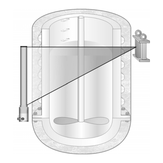
- Page 192 Mounting Marking groove bracket SENSseries LB 480 Fig. 2-18 Point source with rod detector The standard arrangement (Fig. 2-18) shows the mounting position of the shielding with point source; H indicates the topmost point of the measuring range that can be covered. The shielding must be...
- Page 193 The bracket has to be mounted in the appropriate height, if possible, directly on the ves- sel or on another supporting structure. SENSseries LB 480 Level measurement 2 – 193 BERTHOLD TECHNOLOGIES GmbH & Co. KG...
- Page 194 2 Installation Volume 2 Shielding 45° with point source Mounting base 1 Mounting base 2 This version is easier to The version of the mount- make than version 2 ing base with an elongated hole allows the alignment of the source at the detec- tor.
- Page 195 Following installation of the shielding, the function of the locking mechanism has to be tested. The function check has to be carried out every six months and recorded. SENSseries LB 480 Level measurement 2 – 195 BERTHOLD TECHNOLOGIES GmbH & Co. KG...
- Page 196 2 Installation Volume 2 Open shielding After the shielding has been installed, it may be opened only for commissioning. Open the transportation safety device and open the lock. Now use the lever fixed to the base with adhesive tapes and plug it into the borehole for the locking mechanism. Open the beam channel by turning the lever to the right up to the right limit stop.
- Page 197 Depending on the size of the measuring range, this arrangement can be realized with one or several detectors. Source 1 Marking grooves Source 2 SENSseries LB 480 Fig. 2-22 Multi-detector arrangement SENSseries LB 480 Level measurement 2 – 197 BERTHOLD TECHNOLOGIES GmbH & Co. KG...
- Page 198 2 Installation Volume 2 2.6.3 Rod source Increased radiation dose due to open beam channel! A too high dose of radiation may be harmful to your health. A source may be transported only in its shielding. The shielding must be closed during transportation and installation. For rod sources, cylinder-shaped shieldings having the length of Rod source shielding the source are used which are provided with a source exit channel...
- Page 199 (Max). Rod source Fig. 2-25 Rod source arrangement, see also next table SENSseries LB 480 Level measurement 2 – 199 BERTHOLD TECHNOLOGIES GmbH & Co. KG...
- Page 200 2 Installation Volume 2 Shielding diameter (in mm) G (in mm) The installation height of the supporting structure that is to be pro- vided by the customer has to be measured using the dimensional drawings of the shielding. The size and stability of the supporting structure or another suit- able mounting device for the shielding has to match the size and total weight of the shielding.
- Page 201 Following installation of the shielding, the function of the locking mechanism has to be tested. The function check has to be carried out every six months and recorded. SENSseries LB 480 Level measurement 2 – 201 BERTHOLD TECHNOLOGIES GmbH & Co. KG...
- Page 202 2 Installation Volume 2 Open shielding After the shielding has been installed, it may be opened only for commissioning. Open the transportation safety device and open the lock. Now use the lever fixed to the base with adhesive tapes and plug it into the borehole for the locking mechanism. Open the beam channel by turning the lever to the right up to the right limit stop.
- Page 203 Following installation of the shielding, the function of the locking mechanism has to be tested. The function check has to be carried out every six months and recorded. SENSseries LB 480 Level measurement 2 – 203 BERTHOLD TECHNOLOGIES GmbH & Co. KG...
- Page 204 2 Installation Volume 2 Anti-tipping device installed by the installa- tion contractor. Strap e.g. welded to the vessel or the sup- porting structure. The anti-tipping device must be installed on both sides and on each shielding. Mounting base installed by the installation contractor.
- Page 205 Fig. 2-29 Flange shieldings for rod source and point source SENSseries LB 480 Level measurement 2 – 205 BERTHOLD TECHNOLOGIES GmbH & Co. KG...
- Page 206 2 Installation Volume 2 – Rod source with steel cable, one-part or multi-part Versions for flange shieldings – Rod source with shaft core, one-part or multi-part – Point source with steel cable, one-part – Point source with shaft core, one-part Multi-part rod source flange shieldings can be designed such that they can be loaded with up to 5 rod sources.
- Page 207 The shieldings can be adapted to your vessel flange using various flange adapters. SENSseries LB 480 Level measurement 2 – 207 BERTHOLD TECHNOLOGIES GmbH & Co. KG...
- Page 208 2 Installation Volume 2 Shielding with source Pressure control Protection gas Vessel wall Protection tube Dip tube Detector Fig. 2-31 Dip tube installation with point source and point detector If the shieldings are employed in aggressive atmospheres, the steel cable or the shaft core and the latch mechanism have to be checked for corrosion in regular intervals.
- Page 209 Therefore, never close the source locking mechanism as long as not all rod sources are again in the shielding. Otherwise, the steel cable may be kinked or even cut. SENSseries LB 480 Level measurement 2 – 209 BERTHOLD TECHNOLOGIES GmbH & Co. KG...
- Page 210 2 Installation Volume 2 Source end piece (inactive) Steel cable latch, must be latched into the source end piece Positioning screw Clamping screw Steel cable for source positioning Source end piece with clutch Steel cable with Shielding head latch for clutch A source type label is attached on the shielding for Eyebolt...
- Page 211 Connect the shaft core with the source end piece. Shaft core with latch for clutch Source end piece with clutch Fig. 2-34 Shaft core and source end piece SENSseries LB 480 Level measurement 2 – 211 BERTHOLD TECHNOLOGIES GmbH & Co. KG...
- Page 212 2 Installation Volume 2 Fig. 2-35 Connect shaft core and source end piece Open the fixing screw at the head piece. Fig. 2-36 Open fixing screw Open the source shielding. Fig. 2-37 Open source shielding Push the shaft core in up to the limit stop. 54733-10BA2L 2 –...
- Page 213 Fix the position with the fixing screw at the head piece. Attach the covering cap again. Secure the lock with a padlock or the safety screw. The source is now installed. SENSseries LB 480 Level measurement 2 – 213 BERTHOLD TECHNOLOGIES GmbH & Co. KG...
- Page 214 2 Installation Volume 2 2.6.6 Point Source Shielding LB744X The radiation warning sign identi- fies the start of the controlled area, provided the controlled area is out- side the shielding. If the controlled area is inside the shielding, then the radiation warning sign attached on the shielding suffices.
- Page 215 Therefore, install the fixture on a vibration-free support or attenu- ate possible vibrations using vibration absorbers. Prevent heat transfer by using suitable insulating materials. SENSseries LB 480 Level measurement 2 – 215 BERTHOLD TECHNOLOGIES GmbH & Co. KG...
- Page 216 2 Installation Volume 2 The shielding can either be installed on a bracket or on a flange. Installing the shielding Size and position of the measuring range to be covered are deter- mined in the projection phase for the measuring site and defined by drawings, sketches or details in writing.
-
Page 217: Electrical Installation
Equipotential busbar provided by customer Signal line Fig. 3-1 Detector housing open - top view Cable entries that are not used must have dummy plugs installed. SENSseries LB 480 Level measurement 2 – 217 BERTHOLD TECHNOLOGIES GmbH & Co. KG... - Page 218 3 Electrical Installation Volume 2 3.1.1 Multi-detector Operation Refer to the connection diagram for the multi-detector operation in the Technical Information on page 2-241. 3.1.2 ATEX Connection Type Follow the safety instructions in chapter 5, "Explosion Protection", Volume 1. 3.1.3 FM/CSA Connection Type A stopping box (conduit seal) has to be installed on each cable entry used directly behind the detector housing.
-
Page 219: Terminals
(loop through) the supply voltage to the next slave (only permitted for supply of 24 V 5 - 6 RS-485: for Multi-detector operation, connection for slave detector, service interface and software update SENSseries LB 480 Level measurement 2 – 219 BERTHOLD TECHNOLOGIES GmbH & Co. KG... - Page 220 3 Electrical Installation Volume 2 Terminals Master ® HART 11 - 12 Open collector signal output with reverse voltage protection ALARM: no current flowing NORMAL: Current flowing The supply voltage for the open collector must be between 5 and 36V. The maximum current that may flow through the open col- lector is 100mA.
- Page 221 Connect the last slave to terminal 9 Connect the last slave to terminal 10 9 - 10 RS 485: Connection to the next slave detector SENSseries LB 480 Level measurement 2 – 221 BERTHOLD TECHNOLOGIES GmbH & Co. KG...
- Page 222 3 Electrical Installation Volume 2 We recommend using a screened cable for the signal lines. Signal cable with shielding The screen has to be connected to the detector on the PE terminal in the terminal compartment of the detector, or better, to suitable EMC cable glands.
-
Page 223: Connecting The Detector
For detectors that are used in hazardous areas, the detector hous- ing (Fig. 3-4) and thus the pressure-proof enclosure of the elec- tronics may be opened only by the BERTHOLD TECHNOLOGIES ser- vice or by persons authorized by BERTHOLD TECHNOLOGIES. - Page 224 3 Electrical Installation Volume 2 Housing cover Connection head Do not unscrew the 6 screws connecting the detector housing to the connection head. Detector housing Fig. 3-4 Detector housing with connection head Unscrew the housing cover (M5 and M8 Allen wrench). Connecting cables ...
- Page 225 To do this, put the housing cover with the sealing on the housing and tighten the Allen screws using the specified torque: depending on the version, M5 with 4 Nm or M8 with 17 Nm (standard values). SENSseries LB 480 Level measurement 2 – 225 BERTHOLD TECHNOLOGIES GmbH & Co. KG...
- Page 226 3 Electrical Installation Volume 2 Create cable loops with the connected lines in front of the hous- ing entrance and provide for an appropriate strain relief of the connected cables. If there is a danger that the cable may be used as a stepladder, then the cables must be installed pro- tected, for example in conduits.
-
Page 227: Repair, Maintenance And Upkeep
– the detector housing BERTHOLD TECHNOLOGIES recommends to have detectors repaired solely by the BERTHOLD TECHNOLOGIES service or by per- sons authorized by BERTHOLD TECHNOLOGIES. Only original spare parts by BERTHOLD TECHNOLOGIES may be used. Please follow the instructions in the Safety Manual (Volume 1) and the instructions in chapter 3, "Electrical Installation", page 2-217. -
Page 228: Safety Instructions
Repair and maintenance work on the detectors must be performed by competent personnel, see Volume 1, chapter 3, "Qualification of Personnel", page 1-19. If in doubt, return the entire detector for repair to BERTHOLD TECHNOLOGIES. Also note the following points: •... -
Page 229: Replacing The Complete Detector
Allen screws using the specified torque: depending on the version, M5 with 4 Nm or M8 with 17 Nm (standard val- ues). Turn on power. SENSseries LB 480 Level measurement 2 – 229 BERTHOLD TECHNOLOGIES GmbH & Co. KG... - Page 230 4 Repair, Maintenance and Upkeep Volume 2 Enter the previously documented parameters of the detector ® with the exception of the parameter HV-Default via the HART Communicator or an alternative user interface. Perform a new calibration (see Volume 3, chapter 5). Now the detector is ready for operation again.
-
Page 231: Replacing The Electronics Module
Explosion hazard! For detectors used in the Ex-area, the electronics module must be replaced solely by the BERTHOLD TECHNOLOGIES service or by persons authorized by BERTHOLD TECHNOLOGIES. If this is not possible, you must replace the entire detector or return it to the manufacturer for repair. - Page 232 4 Repair, Maintenance and Upkeep Volume 2 Risk of fatal injury due to electric shock! When the housing is open, you may come into contact with live parts if the power supply is connected. Make sure when you open the cover that no supply voltage is applied to the terminals.
- Page 233 See also Volume 3 on page 3- 299. Separate User’s Manuals are available for user interfaces such ™ as SIMATIC PDM or FOUNDATION Fieldbus. This completes the replacement of the electronics module. SENSseries LB 480 Level measurement 2 – 233 BERTHOLD TECHNOLOGIES GmbH & Co. KG...
-
Page 234: Replacing The Crystal-Multiplier Assembly (For Crystalsens)
For detectors used in the Ex-area, the crystal-multiplier assembly must be replaced solely by the BERTHOLD TECHNOLOGIES service or by persons authorized by BERTHOLD TECHNOLOGIES. If this is not possible, you must replace the entire detector or return it to the manufacturer for repair. -
Page 235: Checking The Detector
Photo cathode Fig. 4-2 Scintillation detector The point detector CrystalSENS uses a 50/50 NaI crystal as a scin- tillator, the SuperSENS detector uses a 150/150 scintillator. SENSseries LB 480 Level measurement 2 – 235 BERTHOLD TECHNOLOGIES GmbH & Co. KG... - Page 236 4 Repair, Maintenance and Upkeep Volume 2 4.5.1 Checking the NaI Point Detector (CrystalSENS) Malfunctions of the scintillation counter are not always indicated by a missing pulse rate; it is also possible that the specific Gamma sen- sitivity appears to have changed or obvious instabilities are appar- ent.
- Page 237 Using the adhesive tape, replace the Mu-metal screen, making sure that it is only under light tension. SENSseries LB 480 Level measurement 2 – 237 BERTHOLD TECHNOLOGIES GmbH & Co. KG...
-
Page 238: Customer Service
+49 (0) 7081 177-339 (fax) +49 (0) 7081 177-0 (switchboard)) e-mail: Service@Berthold.com To get efficient help you have to provide the following information: • Detector type or "LB" number, e.g. LB 480 • Information on the error • Information on the application –... -
Page 239: Repair, Return Shipping
Repair, Return Shipping 4.7.1 Electronics, Detector If you intend to return parts or complete detectors for repair, please provide the following information: • Detector type or "LB" number, e.g. LB 480 • Information on the error • Delivery address •... - Page 240 4 Repair, Maintenance and Upkeep Volume 2 54733-10BA2L 2 – 240 02.2017...
-
Page 241: Technical Information
Volume 2 5 Technical Information Technical Information TI LB 480 Level SENSseries LB 480 Level measurement 2 – 241 BERTHOLD TECHNOLOGIES GmbH & Co. KG... - Page 242 5 Technical Information Volume 2 Technical Information Level LB 480 Level Gauge Füllstandmessung Field mounted components Messstellen-Komponenten 54733-10BA2L 2 – 242 02.2017...
- Page 243 25.0 25.5 LB 480-2F 1433 1000 32.0 33.0 LB 480-2J 1933 1500 39.5 40.0 LB 480-2L 2433 2000 48.0 50.0 * WC/WK = Water Cooling / Wasserkühlung SENSseries LB 480 Füllstandsmessung 2 – 243 BERTHOLD TECHNOLOGIES GmbH & Co. KG...
- Page 244 5 Technical Information Volume 2 Dimensions in mm LB 480 Abmessungen in mm 1.2 Examples for Measurement Arrangements with Rod Detector Beispiele für Messanordnungen mit Stabdetektor 54733-10BA2L 2 – 244 02.2017...
- Page 245 2573 2090 2600 60085-050 1077 1100 60085-100 1000 1120 1155 1577 1090 1600 60085-150 1500 1620 1655 2077 1590 2100 60085-200 2000 2120 2155 2577 2090 2600 SENSseries LB 480 Füllstandsmessung 2 – 245 BERTHOLD TECHNOLOGIES GmbH & Co. KG...
- Page 246 5 Technical Information Volume 2 Dimensions in mm LB 480 Abmessungen in mm 1.4 Examples for Mounting Devices and the Installation at the Collimator Beispiele für die Halterung und Montage des Kollimators Detector locking screws with Stabilizer against tilting, installed by customer.
- Page 247 Die Zeichnungen auf dieser Seite sind gültig für Detektoren mit und ohne Wasserkühlung. 2000 1500 1000 1.7 Clamping Position for Multi Detector Arrangement 1.8 Mounting Position for Rod Detector Shieldings Klemmenposition für Multidetektor-Anordnung Klemmenposition für Stabdetektorabschirmungen SENSseries LB 480 Füllstandsmessung 2 – 247 BERTHOLD TECHNOLOGIES GmbH & Co. KG...
- Page 248 LB 480 Abmessungen in mm 2.0 CrystalSENS (Version f. Zone 1/2) LB 480-1.-0. LB 480-1.-1. LB 480-1.-2. LB 480-1.-Z. LB 480-1.-.. -..-r.- LB 480-1.-.. -..-0.- with water cooling mit Wasserkühlung 2.1 CrystalSENS (Version f. Divisions 1/2) LB 480-1.-F. LB 480-1.-G.
- Page 249 Abmessungen in mm 2.3 Point Detector Installation Examples Punktdetektor Installationsbeispiele Application with multipart rod source shielding Application with dip pipe Anordnung mit mehrteiliger Stabstrahler-Abschirmung Anordnung mit Tauchrohr SENSseries LB 480 Füllstandsmessung 2 – 249 BERTHOLD TECHNOLOGIES GmbH & Co. KG...
- Page 250 5 Technical Information Volume 2 Dimensions in mm LB 480 Abmessungen in mm 2.4 Mounting Clamps for Detector Befestigungsschellen für Detektor for Detectors without water cooling for Detectors with water cooling für Detektoren ohne Wasserkühlung für Detektoren mit Wasserkühlung Material 316Ti 1.4571...
- Page 251 Auch die Aufheizung des Detektors durch Wärmeabstrahlung vom Behälter kann durch ein dünnes Wärmeableitblech gemildert werden. Für jeden Detektor steht auch eine geeignete Wasserkühlung (Option) zur Verfügung. SENSseries LB 480 Füllstandsmessung 2 – 251 BERTHOLD TECHNOLOGIES GmbH & Co. KG...
- Page 252 5 Technical Information Volume 2 Dimensions in mm LB 480 Abmessungen in mm 2.7 CrystalSENS Water Cooling Jacket and Adaptor Fittings CrystalSENS Wasserkühlung und Adapter Anschlussstücke tube connection diameter Ø 10 mm Schlaucholive Ø 10 Thread connection R ¼" Gewindeanschluss R ¼"...
- Page 253 Damit sich die Wasserkühlung vollständig mit Wasser füllt, muss der Wasserzufluss von unten erfolgen. bottom 2.9 Detector Cooling Water Demand Detektor Kühlwasserbedarf SENSseries LB 480 Füllstandsmessung 2 – 253 BERTHOLD TECHNOLOGIES GmbH & Co. KG...
- Page 254 5 Technical Information Volume 2 Dimensions in mm LB 480 Abmessungen in mm 54733-10BA2L 2 – 254 02.2017...
- Page 255 3.1 with Side Irradiation mit seitlicher Einstrahlung LB 480-31-..-..-r. Weight/Gewicht 52 kg 3.2 with Side Irradiation and Water Cooling mit seitlicher Einstrahlung und Wasserkühlung LB 480-32-..-..-r. Weight/Gewicht 59 kg SENSseries LB 480 Füllstandsmessung 2 – 255 BERTHOLD TECHNOLOGIES GmbH & Co. KG...
- Page 256 5 Technical Information Volume 2 Dimensions in mm LB 480 Abmessungen in mm 3.3 with Axial Irradiation mit frontaler Einstrahlung LB 480-31-..-..-a. Weight/Gewicht 62 kg 3.4 with Axial Irradiation and Water Cooling mit frontaler Einstrahlung und Wasserkühlung LB 480-32-..-..-a. Weight/Gewicht 69 kg 3.5 SuperSENS (Version f.
- Page 257 Stabstrahler radiation channel Strahlenaustritt pad lock Vorhängeschloss position open Stellung auf position closed Stellung zu name plate Typenschild Type kg/m approx 204.5 11.5 224.5 11.5 11.5 222.5 SENSseries LB 480 Füllstandsmessung 2 – 257 BERTHOLD TECHNOLOGIES GmbH & Co. KG...
- Page 258 5 Technical Information Volume 2 Dimensions in mm LB 480 Abmessungen in mm 4.1 Multipart Installation of Rod Source Shieldings Mehrteilige Installation von Stabstrahler-Abschirmungen Distance shielding to vessel surface: approx. 100mm Abstand Abschirmung zur Behälter-Oberfläche: ca 100mm Tilt protection installed by customer.
- Page 259 Anordnung mit 3 Abschirmungen: II + III + IV Anordnung mit 4 Abschirmungen: II + III + III + IV etc. Shielding / Abschirmung drawing no. Ø Zeichnungs-Nr. 21156.000-000 21157.000-000 21158.000-000 21159.000-000 21160.000-000 21161.000-000 SENSseries LB 480 Füllstandsmessung 2 – 259 BERTHOLD TECHNOLOGIES GmbH & Co. KG...
- Page 260 5 Technical Information Volume 2 Dimensions in mm LB 480 Abmessungen in mm 5. Shielding for Point Source Abschirmungen für Punkt Strahler r r r r The shielding are marked with BOTTOM to rule out any side-inverted installation. Die Abschirmungen sind markiert mit UNTEN um eine seitenverkehrte Installation auszuschließen.
- Page 261 Der Montagesockel 1 ist leichter Die Ausführung 2 des Montagesockels mit herzustellen. dem Langloch, ermöglicht die Ausrichtung des Strahlers auf den Detektor. SENSseries LB 480 Füllstandsmessung 2 – 261 BERTHOLD TECHNOLOGIES GmbH & Co. KG...
- Page 262 5 Technical Information Volume 2 Dimensions in mm LB 480 Abmessungen in mm 6. Pneumatic Actuator for Rod and Point Source Shielding (Type 80 … 270) Pneumatik für Stab- und Punktstrahler-Abschirmungen (Typ 80 … 270) Pneumatic actuator for rod source shielding Pneumatischer Antrieb für Stabstrahler-Abschirmung...
- Page 263 Square neck for position control or for pneumatic actuator. manual operation Rückstellfeder (Fail-Save) mit pneumatischem Antrieb Außenvierkant zur Stellungsanzeige, oder manueller Betätigung Shielding Type 80 … 270 Abschirmung Typ 80 … 270 SENSseries LB 480 Level measurement 2 – 263 BERTHOLD TECHNOLOGIES GmbH & Co. KG...
- Page 264 5 Technical Information Volume 2 Dimensions in mm LB 480 Abmessungen in mm 7. Flange Shielding for Rod Source on Dip Pipe Abschirmungen für Stabstrahler am Tauchrohr 54733-10BA2L 2 – 264 02.2017...
- Page 265 Verschluss erst öffnen wenn der Strahler in das Tauchrohr gefahren werden soll und das Stahlseil, bzw. die Wellenseele eingeklinkt ist. SENSseries LB 480 Level measurement 2 – 265 BERTHOLD TECHNOLOGIES GmbH & Co. KG...
- Page 266 5 Technical Information Volume 2 Dimensions in mm LB 480 Abmessungen in mm 7.2 Flange Adaptors for Rod Source Shieldings Flanschadapter für Stabstrahler-Abschirmungen 54733-10BA2L 2 – 266 02.2017...
- Page 267 Carbon Steel St 37 ND 200 LB 7444-CR Dimensions in drawing / Abmessungen in Zeichnung 6° PN 6 Radiation Angle of the Shielding / Abstrahlwinkel der Abschirmung SENSseries LB 480 Level measurement 2 – 267 BERTHOLD TECHNOLOGIES GmbH & Co. KG...
- Page 268 5 Technical Information Volume 2 Dimensions in mm LB 480 Abmessungen in mm 8.1 Mounting Proposal for Source Shielding LB 744x Montagevorschlag für Abschirmbehälter LB 744x Source Shielding LB 744x Abschirmbehälter LB 744x ~ 30 mm Flange Installation Flanschinstallation Pedestal Installation...
- Page 269 Gehäuseschutzart: EEx e II T6 Option III: 2 Proximity switches EEx ia IIC T6, for intrinsically safe power supply 2 Näherungsinitiatoren EEx ia IIC T6, für eigensichere Speisung SENSseries LB 480 Level measurement 2 – 269 BERTHOLD TECHNOLOGIES GmbH & Co. KG...
- Page 270 5 Technical Information Volume 2 Dimensions in mm LB 480 Abmessungen in mm 8.3 Components for Pneumatic Actuator Einzelteile für Pneumatischen Verschlussantrieb Pneumatic Actuator Return Spring Pneumatischer Antrieb Rückstellfeder male square spin-type handle as position indicator, or for manual operation Außenvierkant zur Stel-...
- Page 271 ND 125 PN 6 LB 8030-02 10° LB 8040-01 30° ND 200 1014 PN 6 LB 8040-02 10° Radiation Angle of the Shielding / Abstrahlwinkel der Abschirmung SENSseries LB 480 Level measurement 2 – 271 BERTHOLD TECHNOLOGIES GmbH & Co. KG...
- Page 272 5 Technical Information Volume 2 Dimensions in mm LB 480 Abmessungen in mm 10. Point Source Flange Shielding LB 81xx for Dip Pipe Installations Punktstrahler-Flansch-Abschirmbehälter LB 81xx für Tauchrohr-Applikationen Type/Typ LB 8115 + LB 8120 Version for 2 Sources LB 81xx-20 Version für 2 Strahler LB 81xx-20...
- Page 273 Klinke in Kupplung einklinken A steel rope or flexible shaft can be used to position the source. Zur Positionierung kann ein Stahlseil oder eine Wellenseele genutzt werden. SENSseries LB 480 Level measurement 2 – 273 BERTHOLD TECHNOLOGIES GmbH & Co. KG...
- Page 274 5 Technical Information Volume 2 Dimensions in mm LB 480 Abmessungen in mm 11. Terminal Connection for Single Detector Elektrischer Anschlussplan für Einzeldetektor 54733-10BA2L 2 – 274 02.2017...
- Page 275 11.1 Multi Detector Connection Diagram Multidetektor-Anschlussplan Up to 16 slaves can be connected at one master. Bis zu 16 Slaves können an einen Master angeschlossen werden. SENSseries LB 480 Level measurement 2 – 275 BERTHOLD TECHNOLOGIES GmbH & Co. KG...
-
Page 276: Ti Lb 480 Towersens
5 Technical Information Volume 2 TI LB 480 TowerSENS 54733-10BA2L 2 – 276 02.2017... - Page 277 Volume 2 5 Technical Information SENSseries LB 480 Level measurement 2 – 277 BERTHOLD TECHNOLOGIES GmbH & Co. KG...
- Page 278 5 Technical Information Volume 2 54733-10BA2L 2 – 278 02.2017...
- Page 279 Volume 2 5 Technical Information SENSseries LB 480 Level measurement 2 – 279 BERTHOLD TECHNOLOGIES GmbH & Co. KG...
- Page 280 5 Technical Information Volume 2 54733-10BA2L 2 – 280 02.2017...
- Page 281 Volume 2 5 Technical Information SENSseries LB 480 Level measurement 2 – 281 BERTHOLD TECHNOLOGIES GmbH & Co. KG...
- Page 282 5 Technical Information Volume 2 54733-10BA2L 2 – 282 02.2017...
- Page 283 Volume 2 5 Technical Information SENSseries LB 480 Level measurement 2 – 283 BERTHOLD TECHNOLOGIES GmbH & Co. KG...
- Page 284 5 Technical Information Volume 2 54733-10BA2L 2 – 284 02.2017...
- Page 285 Volume 2 5 Technical Information SENSseries LB 480 Level measurement 2 – 285 BERTHOLD TECHNOLOGIES GmbH & Co. KG...
- Page 286 5 Technical Information Volume 2 54733-10BA2L 2 – 286 02.2017...
- Page 287 Volume 2 5 Technical Information SENSseries LB 480 Level measurement 2 – 287 BERTHOLD TECHNOLOGIES GmbH & Co. KG...
- Page 288 5 Technical Information Volume 2 54733-10BA2L 2 – 288 02.2017...
-
Page 289: Accessories
Remove the sealing rings from the screwed fitting to adapt them to the cable diameter used. A list of screwed fittings available from BERTHOLD TECHNOLOGIES can be found in the manual for explosion protection on page 1-47. The following is an example for a M20 cable gland with additional sealing ring for small cable diameters, that must be removed for cables with larger diameter. - Page 290 6 Accessories Volume 2 Assembly instructions for ID No. 56091 blueglobe TRI ® – Montageanleitung blueglobe TRI ® – Assembly Instruction Übersicht Bestandteile Schritt 1 – Vorbereitung der Montage Overview components Step 1 – Prepare installation Doppelnippel (A), Feder (B), Globe-Dichteinsatz (C), Druckschraube (D) Leitung abmanteln, Geflecht mit Isolierband schützen Double nipple (A), spring (B), globe-sealing insert (C), pressure screw (D) Dismantle wire, protect braid...
- Page 291 Double nipple Article LA/mm X/mm Torque 1/Nm Torque 2/Nm Adapter [min] für/for für/for Adapter 220bg220msAC13 220bg225msAC15 225bg225msAC17 232bg232msAC23 232bg240msAC27 240bg240msAC31 250bg250msAC36 250bg250msAC40 263bg263msAC46 263bg263msAC51 275bg275msAC61 285bg285msAC70 285bg285msAC78 SENSseries LB 480 Level measurement 2 – 291 BERTHOLD TECHNOLOGIES GmbH & Co. KG...
-
Page 292: Limit Switches For Pneumatics
6 Accessories Volume 2 Limit Switches for Pneumatics Installation and setup instructions for limit-switch box by KINETROL … -003U Ex ed IIC T6 and IMPORTANT If the limit-switch box … -003U is delivered separately, it has to be … -004U stored in a plastic bag until it will be installed. - Page 293 Standard dimensions according to DIN41635 Volt Load (A) Resistor inductive (max.) Lamps up to 12 up to 24 up to 48 0.06 up to 250 0.25 0.03 0.025 SENSseries LB 480 Level measurement 2 – 293 BERTHOLD TECHNOLOGIES GmbH & Co. KG...
-
Page 294: Volume 2
6 Accessories Volume 2 … … Material: -3U and KINETROL …-3U KINETROL …-4U Housing Zinc die casting Coating Epoxy resin, burned in Sealing O-rings (Nitril) Temperature range -25° C to +60° C -20° C to +80° C Weight 1,4 kg Cable inputs M20x1.5 M20x1,5;... - Page 295 Make sure that the cover sealing is inserted in its groove! Slightly grease the housing cover in the shaft duct with MoS grease, attach it and tighten cover screws. SENSseries LB 480 Level measurement 2 – 295 BERTHOLD TECHNOLOGIES GmbH & Co. KG...
- Page 296 6 Accessories Volume 2 Correction of the switching points Direct installation for drive with pre-assembled Unscrew the cover of the supplied limit-switch box and pull it limit-switch box off, as shown in the illustration, while pushing down the limit-switch shaft. Caution: Do not lose the cover sealing! Push ...
- Page 297 Volume 2 Notes: SENSseries LB 480 Level measurement 2 – 297 BERTHOLD TECHNOLOGIES GmbH & Co. KG...
- Page 298 Subject to change in the course of further technical development. © BERTHOLD TECHNOLOGIES GmbH & Co. KG 2009 Language: English Printed in Germany 02.2017 Rev. No.: 03 BERTHOLD TECHNOLOGIES GmbH & Co. KG Calmbacher Str. 22 D-75323 Bad Wildbad Germany www.Berthold.com...
-
Page 299: Operation With Hart Communicator
Volume 3 Operation with ® HART Communicator... - Page 300 Volume 3 54733-10BA2L 3 – 300 02.2017...
-
Page 301: Hart ® Communication
® Volume 3 1 HART Communication ® HART Communication The LB 480 can be operated with the following hosts: ® • HART Communicator (375/475) by Emerson Process • Siemens Simatic PDM • AMS DeltaV by Emerson Process HART® Protocol The measured value in % level is transferred in the process variable PV. -
Page 302: Connection, Power On And Power Off Of The Hart ® Communicator
Risk of explosion! ® In hazardous areas, a HART Communicator may be connected only under the following conditions: – the current output of the measuring system SENSseries LB 480 is intrinsically safe ® – the HART Communicator is intrinsically safe ®... -
Page 303: Archiving Parameter Sets
Depending on the HOST system, it may happen that certain param- eters are not stored correctly. Therefore, verify the data stored after each archiving step. Even if you restore the saved data to the LB 480, you have to check the calibration setting afterwards. SENSseries LB 480 Level measurement 3 –... - Page 304 ® 1 HART Communication Volume 3 ® 1.5.1 HART Communicator ® The HART Communicator Model 375/475 allows you to archive parameters sets. For this purpose, the parameter set first has to be saved using the software button SAVE from the detector to the SD ®...
- Page 305 The detector is now ready for measurement. ® To update the data, you have to restart the HART Communicator. For archiving with other hosts please see the following chapter. SENSseries LB 480 Level measurement 3 – 305 BERTHOLD TECHNOLOGIES GmbH & Co. KG...
- Page 306 ® 1 HART Communication Volume 3 1.5.2 PDM (Siemens Simatic PDM) The PDM can also store data in the offline menu. Again, you have to select Recall on the Cal Parameter menu. When restoring the data to the detector, it is necessary to transfer the data twice to the detector.
-
Page 307: Menu Structure
The following sections assume that you: • know how to work with the Communicator • Volume 2 have read and understood ("Installing SENSseries") of this User’s Manual. SENSseries LB 480 Level measurement 3 – 307 BERTHOLD TECHNOLOGIES GmbH & Co. KG... -
Page 308: Menu Overview
Volume 3 Menu Overview Live Display Setup Operating Mode Quick Start continued on page Level Sensor Configuration 3-309 Current Out Signal Condition Cps Average Op Cal Parameter continued on page Cps Average I/O Setup 3-310 Cps Live Service Cps Average Comp page 3-316 GPC Comp Factor HV Live... - Page 309 The parameters shown in gray type appear only in Setup certain settings. Quick Start, page 3-317 Please refer to the respective parameter description. Quick Start Sensor Configuration Step 1 Step 2 Step 3 Signal Condition Date Time Constant Read In Time Nuclide Background...
- Page 310 Volume 3 Setup Cal Parameter, page 3-335 Cal Points Cal Settings Product Conditions Calc Comp Factor Adapt Calibration Calibrate Recall ReadIn Nuclide Measuring Path ReadIn Adjust Lower Point page 3-337 page 3-336 Background Calibration Method Product Density Comp Table Index (page 3-351) Cal Parameter Background Comp...
- Page 311 Diagnostic Operating Status Operating Status Device Status Device Status Safety Ext dev status page 3-382 Slave Status Device Variables Status Error Status 100…907 Config Change Status Ext dev status Lock Dev Status page 3-381 Error Status page 3-382 page 3-382 Error Log Error Log Device Variables Status...
- Page 312 Volume 3 Active Detector No. HV Live HV Feedback Meas CH CPS Control CH CPS Auxiliary CH CPS PMT Current PMT Current Max Reset Current Extrema Service page 3-364 Sensor Temperature Sensor Temperature Test Test, page 3-366 Device Temp. Plateau Test Settings I/O Test Settings Device Temp.
-
Page 313: Start Menu
2 Device Config 316). Opens the menu displaying status and error information and the 3 Diagnostic protocols for errors and parameter changes (page 3-381). Menu Structure SENSseries LB 480 Level measurement 3 – 313 BERTHOLD TECHNOLOGIES GmbH & Co. KG... -
Page 314: Live Display
Menu Structure Volume 3 Live Display Shows the current operating status. 1 Operating Mode The following states may occur: • The measurement is in the normal measurement mode. • WARNING A warning message is displayed. If the error is no longer displayed in Active Error, you can check the error log (Device Config ... - Page 315 Displays the temperature inside the detector. 10 Device Temp. Displays the trend of important measured values such as level, 11 Trend count rate and temperature. SENSseries LB 480 Level measurement 3 – 315 BERTHOLD TECHNOLOGIES GmbH & Co. KG...
-
Page 316: Device Config
Menu Structure Volume 3 Device Config Opens the Setup menu. If Setup !locked! appears here, then the 1 Setup access has to be enabled via Access (page 3-316). Leads to the menu displaying the currently valid measurement 2 Meas Parameter parameters that are used to determine the measured value (page 3-373). -
Page 317: Quick Start
If an error occurs, you can see in the error log (Device Config Diagnostic Log, page 3-387) when exactly the error occurred. SENSseries LB 480 Level measurement 3 – 317 BERTHOLD TECHNOLOGIES GmbH & Co. KG... -
Page 318: Quick Start, Step 2
Menu Structure Volume 3 Quick Start, Step 2 The time constant smoothes the output signal. Statistical fluctua- 1 Time Constant tions, as well as level fluctuations due to the process, e.g. by agita- tors, are smoothed. A time constant of 20 s is usually reasonable. ... - Page 319 Finally, you are prompted to confirm the detected count rate with OK. To shorten the read-in process, you can stop any time by pressing OK. SENSseries LB 480 Level measurement 3 – 319 BERTHOLD TECHNOLOGIES GmbH & Co. KG...
- Page 320 Menu Structure Volume 3 The term background refers to the background radiation which is 2 Background present in the environment. The background radiation has to be measured so that the detector can correctly compensate for the decay of the radiation source. ...
- Page 321 6-DATE ERROR A date is still set to the default value of 1.1.2000. At Calibrate, check the Date parameter. At Restore, check the date in Restore Date. SENSseries LB 480 Level measurement 3 – 321 BERTHOLD TECHNOLOGIES GmbH & Co. KG...
-
Page 322: Sensor Configuration
Menu Structure Volume 3 • 7-CHECK ERROR The status of the calibration parameters could not be fully veri- fied. In this case, repeat the calibration. If the error occurs again, replace the detector, at least the detector electronics. The above described plausibility check cannot prevent that the user may read-in incorrect data. -
Page 323: Date & Time
Detector No. = 1 shows the date and time of slave 1. • Detector No. = 2 shows the date and time of slave 2. • etc. SENSseries LB 480 Level measurement 3 – 323 BERTHOLD TECHNOLOGIES GmbH & Co. KG... -
Page 324: Sensor Settings
® Shows the specific HART device number of the active detector. 3 Detector Device Id This information is set up by BERTHOLD TECHNOLOGIES and edited be changed by the user. The currently selected detector code is displayed. 4 Detector Code The detector code is crucial for the proper function of the automatic HV control (high voltage control). - Page 325 If you change HV Default, HV Average automatically takes over the value from HV Default. You can enter a fixed HV value. The value becomes active when you 8 HV Manual select MANUAL at HV-Mode. SENSseries LB 480 Level measurement 3 – 325 BERTHOLD TECHNOLOGIES GmbH & Co. KG...
- Page 326 Menu Structure Volume 3 HV Default causes: 9 HV Default – A quick operation point control after power failure After a power failure, the HV starts at the last HV Average value which results from the HV Default. This will significantly reduce the start-up phase after power failure.
-
Page 327: Config Slave Detectors
An error message is displayed with a three digit number. The cause of the error and suggestions for correcting the error are described in "Error Handling" in chapter 8. SENSseries LB 480 Level measurement 3 – 327 BERTHOLD TECHNOLOGIES GmbH & Co. KG... -
Page 328: Signal Condition
Menu Structure Volume 3 2.15 Signal Condition Menu path: Device Config Setup Signal Condition. This menu contains some special features which have a direct impact on the signals of the measurement: – the way of signaling – general warning and error messages –... -
Page 329: Signal Parameter
Out Function (Device Config Setup I/O Setup Digital Output Digital Out Function, page 3-357). Error handling is described in detail in chapter 8 starting on page 3- 429. SENSseries LB 480 Level measurement 3 – 329 BERTHOLD TECHNOLOGIES GmbH & Co. KG... -
Page 330: Reading Range
Menu Structure Volume 3 You will get alerted when the device is unlocked with a password. 4 Signal Unlocked The warning message 901 is output. Choose WARNING only if the control system is to be alerted when the device was unlocked with the password. -
Page 331: Signal Dependency
SENSseries LB 480 Level measurement 3 – 331 BERTHOLD TECHNOLOGIES GmbH & Co. KG... - Page 332 Menu Structure Volume 3 IMPORTANT The function RAPID SWITCH should not be enabled when the measurement is installed into a control loop, since this function works with two different time constants. Defines the threshold where the interference radiation detection 2 Io Factor responds.
-
Page 333: Source Exchange
If you have selected DATE at Selection, you have to enter the date 2 Warning Date when you want to get the Source Exchange warning (format: MM/ DD/YYYY. SENSseries LB 480 Level measurement 3 – 333 BERTHOLD TECHNOLOGIES GmbH & Co. KG... - Page 334 Menu Structure Volume 3 If you have selected Reading Fluctuation at Selection, you have 3 Max Reading Fluctuation to enter here the maximum fluctuation width of the level reading. The value entered refers to a plus/minus fluctuation around the mean value with a probability of occurrence of two Sigma. After entry of a value, the date on which the warning will be expected is displayed in Warning Date.
-
Page 335: Cal Parameter
Cal Parameter; rather, it must be changed using the values from Meas Parameter. These values correspond to the data the LB 480 is currently using to run measurements. The data in Meas Parameter also include the decay compensated count rates of the calibration points which were used last to calibrate the LB 480. - Page 336 Menu Structure Volume 3 With this menu item you enable the calibration data determined 6 Calibrate during the measurements. In this case, the calibration data are transferred from Cal Parameter to Meas Parameter. Thus, the detector will get a new calibration which in the future will be used to determine the measured values.
-
Page 337: Cal Points
Changes in this parameter group have an effect only when you call Calibrate (Device Config Setup Cal Parameter Calibrate, page 3-335). This menu allows you to adjust the measuring system. SENSseries LB 480 Level measurement 3 – 337 BERTHOLD TECHNOLOGIES GmbH & Co. KG... - Page 338 Menu Structure Volume 3 Start reading-in the count rates. While the count rate is read in, the 1 ReadIn average is calculated and displayed continuously. You define the reading-in period under ReadIn Time (Device Config Setup Cal Parameter Cal Setting). First choose which calibration point you want to read in: •...
- Page 339 9 Sort level to high level, then the calibration points can be sorted using this menu item. The calibration points must be sorted before enabling Calibrate! SENSseries LB 480 Level measurement 3 – 339 BERTHOLD TECHNOLOGIES GmbH & Co. KG...
- Page 340 Menu Structure Volume 3 Allows a clear presentation of the calibration points. 10 Calibration Chart • Max Nbr Cal Points Displays the maximum possible number of calibration points. • Refresh Cal Table Updates the calibration points contained in Cal Table. •...
-
Page 341: Cal Settings
If you perform a calibration with the gas den- sity compensation GDA, or a 1-point calibration, the wrong isotope will also calculate wrong calibration data. SENSseries LB 480 Level measurement 3 – 341 BERTHOLD TECHNOLOGIES GmbH & Co. KG... - Page 342 Menu Structure Volume 3 Different calibration methods are used depending on the application 2 Calibration Method and the local conditions. If you need help, please refer to chapter 7.3 and chapter 7.4. You can choose from the following calibration methods: •...
-
Page 343: Product Conditions
The value to be entered is the length of the beam path through the measured product. Point source Point detector 100% 100% Measuring Path Measuring Path 100% Product Product Product Point detector SENSseries LB 480 Level measurement 3 – 343 BERTHOLD TECHNOLOGIES GmbH & Co. KG... - Page 344 Menu Structure Volume 3 This parameter is required for Calibration Method 1-POINT to 2 Product Density determine the full count rate automatically. For liquids you have to enter the fluid density in kg/m , for solids, the bulk density. If you known the fluid density and the bulk density only approxi- mately, then you have to enter the lowest expected value.
- Page 345 Cs-137, then the compensation measurement must also be carried out with Cs-137. GPC cannot be used for a level measurement with point source and point detector. SENSseries LB 480 Level measurement 3 – 345 BERTHOLD TECHNOLOGIES GmbH & Co. KG...
- Page 346 Menu Structure Volume 3 Visible only if Compensation Mode is set to MANUAL GDA. 4 Gas Measuring Path Enter the average measurement path through the gas-filled room. With point sources and rod detectors: Point source The path from the point source to the center of the measuring range.
- Page 347 Prerequisite for the proper correction are correct entries in the fol- lowing menu items: • Setup Gas Density • Op Gas Density • Measuring Path • Nuclide SENSseries LB 480 Level measurement 3 – 347 BERTHOLD TECHNOLOGIES GmbH & Co. KG...
- Page 348 This effect can be compensated by a increasing the gas density to be entered. If you cannot determine the increased absorption, please contact BERTHOLD TECHNOLOGIES. Visible only if Compensation Mode is set to MANUAL GDA. 6 Gas Density at Op ...
-
Page 349: Calc Comp Factor
Comp Table Index. Select ReadIn to read in the count rate. If you already know the value, you can enter it here. SENSseries LB 480 Level measurement 3 – 349 BERTHOLD TECHNOLOGIES GmbH & Co. KG... -
Page 350: Adapt Calibration
Menu Structure Volume 3 Calculates the compensation factor resulting from the measuring 5 Calculate Factor points in this menu. This factor corresponds to the slope of the characteristic curve. The calculated value is displayed in parameter Comp Factor. Includes the compensation factor determined using this menu. It 6 Comp Factor compensates for differences in measurement sensitivity between the level measurement and the gas density measurement. -
Page 351: Adjust Lower Point
0%. If 0% is not possible, the lower calibration point can also be read in at a low level, for example, 20%. SENSseries LB 480 Level measurement 3 – 351 BERTHOLD TECHNOLOGIES GmbH & Co. KG... - Page 352 Menu Structure Volume 3 Count rate with empty container or 0% level. If 0% is not possible, 3 Lower Rate the lower calibration point can also be read in at a low level, for example, 20%. Select ReadIn to read in the count rate. If you already know the value, you can enter it here.
-
Page 353: Adjust Upper Point
6 Adjust Curve UP Level + Upper Rate) and the calibration curve which is stored under Cal Points. The new curve is also stored under Cal Points. SENSseries LB 480 Level measurement 3 – 353 BERTHOLD TECHNOLOGIES GmbH & Co. KG... -
Page 354: I/O Setup
Menu Structure Volume 3 2.28 I/O Setup Menu path: Device Config Setup I/O Setup. This menu allows you to set the analog and digital inputs and out- puts and the interfaces. Opens the menu with the settings for the current output (page 3- 1 Current Output 355). -
Page 355: Current Output
In case of error the current output holds the last measured value. • Value In case of error, the current output is set to the current value, which is set in Error Current Value. SENSseries LB 480 Level measurement 3 – 355 BERTHOLD TECHNOLOGIES GmbH & Co. KG... - Page 356 Menu Structure Volume 3 Here you can define the fault current in mA, if you have chosen 3 Error Current Value Value at Loop Alarm Type. With the settings High and Low, the corresponding current values are displayed (>21mA/ <3.6mA).
-
Page 357: Digital Output
The alarm is triggered when the detector signals an error or reports a warning. In chapter 8 on page 3-429 you find a list of possible causes and troubleshooting procedures. SENSseries LB 480 Level measurement 3 – 357 BERTHOLD TECHNOLOGIES GmbH & Co. KG... - Page 358 Menu Structure Volume 3 • RAD. INTERFERENCE The alarm is triggered when interference radiation is detected. The function can be selected only if you have selected RAD. INTERFERENCE at Response Mode (Device Config Setup Signal Condition Radiation Interference Response Mode, page 3-331).
-
Page 359: Level Threshold Settings
Enter the level limit value in % where the alarm is to be output. 2 Threshold The hysteresis prevents switching back and forth caused by statis- 3 Hysteresis tical fluctuations of the measured values. The default value is 5%. SENSseries LB 480 Level measurement 3 – 359 BERTHOLD TECHNOLOGIES GmbH & Co. KG... -
Page 360: Temp. Threshold Settings
Menu Structure Volume 3 2.32 Temp. Threshold Settings Menu path: Device Config Setup I/O Setup Digital Output Temp. Threshold Settings. Upper limit value for the detector temperature. 1 Temp. Upper Limit An alarm may be signaled via the digital output if this temperature is exceeded. -
Page 361: Digital Input
Runs a full calibration. The input must be closed only briefly in order to start the process. Indicates whether the input is open or closed. 2 Digital In State SENSseries LB 480 Level measurement 3 – 361 BERTHOLD TECHNOLOGIES GmbH & Co. KG... -
Page 362: Hart Interface
Menu Structure Volume 3 2.34 HART Interface Menu path: Device Config Setup I/O Setup HART Interface. Shows the current polling address. The address can be set with Set 1 Poll Addr Poll Address. Allows you to set the polling address for multidrop operation. 2 Set Poll Address Enter only a polling address >... -
Page 363: Service
5 License Key tions (level, density). You can get a license key through your sales partner or directly from BERTHOLD TECHNOLOGIES GmbH & Co. Write down your license key in your operating manual. Each detec- tor has its own license key. -
Page 364: Pmt
Menu path: Device Config Setup Service PMT. This menu allows the qualification of the photomultiplier (PMT) after consultation with BERTHOLD TECHNOLOGIES. Increased current values at the multiplier indicate a strong radiation levels (caused, for example, by weld testing), or a defect at the PMT, or the HV con- trol. -
Page 365: Sensor Temperature
Display of the highest temperature measured. 3 Device Temp. Max Clears the stored values in Device Temp. Min and Device Temp. 4 Reset Temp Extrema Max. SENSseries LB 480 Level measurement 3 – 365 BERTHOLD TECHNOLOGIES GmbH & Co. KG... -
Page 366: Test
Menu Structure Volume 3 2.38 Test Menu path: Device Config Setup Service Test. These menus allow you to perform various tests on the detector. All tests have a direct influence and are not delayed by the time con- stant. - Page 367 6 Cps Comp Average Test or AUTO PRC is enabled. Enter the value to be simulated. To enable the simulation, you must set FIXED VALUE at Cps Average Mode. SENSseries LB 480 Level measurement 3 – 367 BERTHOLD TECHNOLOGIES GmbH & Co. KG...
- Page 368 Menu Structure Volume 3 Allows you to verify if over- or under-temperature is signaled via the 7 Device Temp. Mode digital output. Enter a test temperature and then check the signal at the digital output. To check the digital output with a test temperature, you have to: 1.
-
Page 369: I/O Test Settings
Choose OPEN or CLOSED to check the appropriate reaction of 4 Digital In Test State the detector. To enable the simulation, you must set FIXED VALUE at Digital In Mode SENSseries LB 480 Level measurement 3 – 369 BERTHOLD TECHNOLOGIES GmbH & Co. KG... -
Page 370: Plateau
Menu Structure Volume 3 Indicates whether the current output is active or frozen. The follow- 5 Loop Current Mode ing displays are possible: • ENABLED The current output is active. • DISABLED The current output is frozen. The current output is frozen in the following cases: –... -
Page 371: Plateau Measurement
At the end of the plateau measurement the detector automati- cally switches back to HV Mode: AUTO or MANUAL, depend- ing on which mode was last set. SENSseries LB 480 Level measurement 3 – 371 BERTHOLD TECHNOLOGIES GmbH & Co. KG... -
Page 372: Plateau View
Menu Structure Volume 3 Displays the current HV (high voltage) at the photomultiplier. If 7 HV Live HV Mode is set to AUTO (normal operation), the values in HV Live must change, viewed over several seconds. Display of the count rate of each master or slave detector. 8 Cps Single Detector Displays the current total count rate of all detectors. -
Page 373: Meas Parameter
2 Meas Table Using this table, the measurement shows the current level. After calibration, the calibration points are displayed here in a cali- 3 Measurement Curve bration curve. SENSseries LB 480 Level measurement 3 – 373 BERTHOLD TECHNOLOGIES GmbH & Co. KG... -
Page 374: Meas Settings
Menu Structure Volume 3 2.47 Meas Settings Menu path: Device Config Meas Parameter Meas Settings. Shows the time constant used to average the measured value. 1 Time Const Display of the isotope (nuclide) selected for the calibration. It must 2 Nuclide be the same as the source which is used at the measuring site. -
Page 375: Meas Readings
Detector No. = 1 shows the count rate of slave 1. • etc. Shows the count rate of the detector, which you had selected with 8 Cps Single Detector Active Detector No.. SENSseries LB 480 Level measurement 3 – 375 BERTHOLD TECHNOLOGIES GmbH & Co. KG... -
Page 376: Access
Possibly activated test settings are reset when enabling password protection. Write down your password to be able to unlock the detector later. Please contact BERTHOLD TECHNOLOGIES if you lose your pass- word. Indicates whether the detector is protected against changes in the 2 Write Protect settings (parameters). - Page 377 SIL on the type plate can be used with the SIL data in the safety manual in a safety circuit. SIL-certified detectors are marked with an "S" in the LB number key LB 480-xx-xx-xx-xx-xSx- In safety mode, safety-limiting values are set to a safety-compati- ble setting.
-
Page 378: Identification
Menu Structure Volume 3 Disables the safety mode. You need the password to disable the 5 Safety OFF safety mode. If you disable the safety mode, the following settings are made automatically: – Write Protect is set to OFF – Error Handling is set to NORMAL (see page 3-329). -
Page 379: Device Information
TECHNOLOGIES and edited be changed by the user. Shows the manufacturer's name. This information cannot be edited 3 Manufacturer by the user. Number for identification of the detector. 4 Final Assembly Num SENSseries LB 480 Level measurement 3 – 379 BERTHOLD TECHNOLOGIES GmbH & Co. KG... -
Page 380: Device Revision
Software revision with presentation according to NAMUR. 4 SW Revision Date of the software revision. 5 SW Revision Date Shows the hardware revision. This information is set up by 4 Hardware Rev BERTHOLD TECHNOLOGIES and edited be changed by the user. 54733-10BA2L 3 – 380 02.2017... -
Page 381: Diagnostic
Here you can check the status of all error messages that are possi- 5 Error Status 100 … 907 ble in the detector. • OFF = error free • ON = an error is indicated SENSseries LB 480 Level measurement 3 – 381 BERTHOLD TECHNOLOGIES GmbH & Co. KG... -
Page 382: Operating Status
Menu Structure Volume 3 2.55 Operating Status Menu path: Diagnostic Operating Status. ® Displays the current device status (standard HART command). 1 Device Status ® Shows the extended device status (standard HART command, 2 Ext dev status page 3-382). Opens the menu showing the status of the detector variable (stan- 3 Device Variables Status ®... -
Page 383: Device Variables Status
Indicates to what extent the device is locked against access to the ® HART interface by other devices. – Device is Locked – Lock is Permanent – Locked by Primary Master SENSseries LB 480 Level measurement 3 – 383 BERTHOLD TECHNOLOGIES GmbH & Co. KG... -
Page 384: Error Status
Menu Structure Volume 3 2.60 Error Status Menu path: Diagnostic Operating Status Error Status. Displays the status of the calibration parameters. The status is 1 Meas Setup Status updated after each decay compensation (at 09:01 h) and after each date change. - Page 385 (Device Config Diagnostic Log, page 3-387). In chapter 8 on page 3-429 you find a list of pos- sible causes and troubleshooting procedures. SENSseries LB 480 Level measurement 3 – 385 BERTHOLD TECHNOLOGIES GmbH & Co. KG...
- Page 386 Menu Structure Volume 3 – SHUTDOWN An serious error is displayed and the following steps are carried out: – entry in the error log (the error is stored in the error mem- ory) ® – the error will be reported digitally via HART –...
-
Page 387: Log
An error message is displayed with a three digit number. The cause of the error and suggestions for correcting the error are described in chapter 8, "Error Handling". Acknowledges the currently pending error. 5 Acknowledge Error SENSseries LB 480 Level measurement 3 – 387 BERTHOLD TECHNOLOGIES GmbH & Co. KG... -
Page 388: Modification Log
Menu Structure Volume 3 2.63 Modification Log Menu path: Diagnostic Log Modification Log. Update the modification log by selecting Refresh Modification Log before you select one of the following menu items. Otherwise, no or only old entries may be displayed. Updates the modification log. -
Page 389: Getting Started Via The Hart
3 Getting Started via the HART Communicator Getting Started via the ® HART Communicator The measuring system SENSseries LB 480 is compatible with the ® 375 Field Communicator (HART Communicator, HART = Highway Addressable Remote Transducer) by Emerson ® Process Management GmbH & Co. OHG. Other HART... - Page 390 ® 3 Getting Started via the HART Communicator Volume 3 54733-10BA2L 3 – 390 02.2017...
-
Page 391: Quick Guide To Calibration
Step 1 - Date/Time Check and update the time. Select Nuclide: Cs-137 or Co-60 (see type plate of the source Step 2 - Setup shielding). SENSseries LB 480 Level Measurement 3 – 391 BERTHOLD TECHNOLOGIES GmbH & Co. KG... - Page 392 4 Quick Guide to Calibration Volume 3 At the CrystalSENS you can skip the following item Background, Step 3 - Calibration Points unless the measurement is safety-relevant. Background The source shielding is not mounted at the measuring point, but at least it is adequately shielded (see chapter 7.1, page 3-411).
-
Page 393: Calibration
Prerequisites for calibration with ® mains (see Volume 2, chapter 2 and chapter 3). the HART Communicator ® – The HART Communicator is connected to the current loop. SENSseries LB 480 Level measurement 3 – 393 BERTHOLD TECHNOLOGIES GmbH & Co. KG... -
Page 394: Preparing Calibration
5 Calibration Volume 3 Preparing Calibration For correct calibration of the measuring system, you have to ensure that the detector and basic settings are correct. ® Turn the HART Communicator on. After power on, the Start menu appears. Push HOME to return from any level back to the Start menu. If the detector has been in stock for a long time, it may happen that the internal clock no longer displays the current date. - Page 395 This completes the adjustment of the HV Default value. 5.1.3 Detector Code Set the detector code according to the table in Volume 2, chapter 1.6, "Detector Codes". SENSseries LB 480 Level measurement 3 – 395 BERTHOLD TECHNOLOGIES GmbH & Co. KG...
-
Page 396: Calibration With Quick Start
5 Calibration Volume 3 Calibration with Quick Start 100% Fig. 5-1 Two-point calibration This chapter describes the calibration in the Quick Start menu in detail. A quick reference guide can be found in chapter 4. The Quick Start menu allows a two-point calibration with empty and full calibration. - Page 397 However, the correct time is helpful to check the detector function: In case of error, you can see in the error log when the error occurred. SENSseries LB 480 Level measurement 3 – 397 BERTHOLD TECHNOLOGIES GmbH & Co. KG...
- Page 398 5 Calibration Volume 3 5.2.2 Step 2 Enter the desired time constant. Time Constant The time constant smoothes the output signal. Statistical fluctua- tions and level fluctuations due to the process, e.g. by agitators, are smoothed. A time constant of 20 s is usually reasonable. ...
- Page 399 – Cooling/Heating jacket Under ReadIn select Cal Point 0%. Confirm with OK as soon as Remaining Time = 0s. Level below the monitoring limit SENSseries LB 480 Level measurement 3 – 399 BERTHOLD TECHNOLOGIES GmbH & Co. KG...
- Page 400 5 Calibration Volume 3 Read in Cal Point 100% For the measurement, the level in the tank must be filled to at least 100% or the tank must be completely filled. While you read-in, the conditions within the tank must as far as possible match the condi- tions during operation.
- Page 401 In order to avoid the risk that the device supplies faulty signals, it is imperative that you familiarize yourself with these additional fea- tures before you use them. SENSseries LB 480 Level measurement 3 – 401 BERTHOLD TECHNOLOGIES GmbH & Co. KG...
-
Page 402: Ensuring The Function Of The Measurement
At the same time, you can also compare the measured value display in the control system for every single count rate with the measured value displayed in the LB 480 to ensure the correct transfer of the measurement signal. After this simulation has been completed, you have to switch the parameter Cps Average Mode back to NORMAL. - Page 403 Since only one point within the measur- ing range is tested, it must be clarified whether this test is sufficient for the application. If in doubt, please ask the BERTHOLD TECHNOLOGIES Service for support. SENSseries LB 480 Level measurement 3 –...
- Page 404 Fill out the parameter protocol in the Appendix to the operating instructions • Digital storage of data Several options are available for digital storage, depending on the communication interface and host used: • LB 480-PC (Berthold specific program for the RS485 interface) ® • HART Communicator • Siemens Simatic PDM •...
-
Page 405: Functional Processes
At last, check your entries for the multi-detector operation using the table, which you can access under Slave Table. SENSseries LB 480 Level measurement 3 – 405 BERTHOLD TECHNOLOGIES GmbH & Co. KG... -
Page 406: Plateau Measurement
6 Functional Processes Volume 3 Plateau Measurement These parameters determine how the plateau measurement is to be performed. Below we will describe how to perform a plateau measurement. The plateau measurement checks the function of the detector. IMPORTANT The radiation conditions must be constant while recording the pla- teau! 1100 1000... - Page 407 The plateau measurement is now complete and can be viewed and reviewed under Plateau View as a table or plateau curve. SENSseries LB 480 Level measurement 3 – 407 BERTHOLD TECHNOLOGIES GmbH & Co. KG...
-
Page 408: Master Reset
Risk of explosion! For detectors that are used in hazardous areas, the housing must only be replaced by the BERTHOLD TECHNOLOGIES service or by persons authorized by BERTHOLD TECHNOLOGIES. If this is not possible, you must replace the entire detector or return it to the manufacturer for repair. - Page 409 Configuration Sensor Settings Detector Code, see page 2-166. 16. Set HV Default, see chapter 5.1.2. This completes the reset, the detector is now ready for cali- bration. SENSseries LB 480 Level measurement 3 – 409 BERTHOLD TECHNOLOGIES GmbH & Co. KG...
- Page 410 6 Functional Processes Volume 3 54733-10BA2L 3 – 410 02.2017...
-
Page 411: Explanations
(approx. 15 m), or behind a thick concrete wall. Detector Detector Fig. 7-1 Best solution SENSseries LB 480 Level measurement 3 – 411 BERTHOLD TECHNOLOGIES GmbH & Co. KG... - Page 412 7 Explanations Volume 3 With a full container, mounted detector and attached shielding and Second best solution with the radiation sources installed and closed source exit channel. Source with closed source exit channel Detector Fig. 7-2 Second best solution This procedure is recommended only for Cs-137 sources. Third best solution With an empty tank, mounted detector and attached shielding and built-in radiation sources and closed source exit channel.
-
Page 413: Conditions For Empty Calibration
IMPORTANT For wall deposits a measurement system with a Co-60 source is less sensitive than one with a Cs-137 source. SENSseries LB 480 Level measurement 3 – 413 BERTHOLD TECHNOLOGIES GmbH & Co. KG... - Page 414 7 Explanations Volume 3 Agitator • The agitator must be in operation if it has any impact on the measurement. High gas pressure • If the container is under high gas pressure during operation, the empty calibration also has to be carried out under this gas pressure.
-
Page 415: Linear And Exponential
The relation between level and count rate is an exponential func- Exponential tion. 100% Fig. 7-5 Exponential This calibration is used in applications involving point sources and point detectors SENSseries LB 480 Level measurement 3 – 415 BERTHOLD TECHNOLOGIES GmbH & Co. KG... - Page 416 7 Explanations Volume 3 7.3.1 Exponential one-point calibration If the container cannot be completely filled after operation has started, then a one-point calibration can be performed. To this end, enter a measuring path and product density. Then an empty adjustment is performed; to this end, enter the original level value as a percentage, and the corresponding count rate.
-
Page 417: Multi-Point Calibration
Often water is used as replacement for the product. Please contact our field ser- vice staff, or BERTHOLD TECHNOLOGIES directly to get more infor- mation on optimum calibration. Try to record as many value pairs as possible, but use as few value pairs as possible for calibration. - Page 418 7 Explanations Volume 3 7.4.1 Explanation on the Calibration of Lower Cali- bration Point This empty calibration will have influence on the whole curve. Due to this, all count rates will be adjusted. That will keep the shape of the curve, because all calibration points are extrapolated as per- centage of the difference between the old- and the new "lower cal- ibration point".
- Page 419 0% : 5000cps Example from the table at 70% cps 0% : 7000cps (70%): 3000cps : 100cps = (3000-100) * (5000-100)/(7000-100) + 100 = 2159cps SENSseries LB 480 Level measurement 3 – 419 BERTHOLD TECHNOLOGIES GmbH & Co. KG...
-
Page 420: Radiation Interference Detection
7 Explanations Volume 3 Radiation Interference Detection Pipe Radiation interference Welding seam tests with X-rays up to 200 m Fig. 7-11 Radiation interference 7.5.1 Detecting Interference Radiation The high Gamma sensitivity of scintillation detectors may cause a false reading. To detect interfering radiation, a double plausibility check can be enabled. - Page 421 However, it would be better not to enable the interfering radiation detection at first. Enable the inter- fering radiation detection only after calibration. SENSseries LB 480 Level measurement 3 – 421 BERTHOLD TECHNOLOGIES GmbH & Co. KG...
- Page 422 7 Explanations Volume 3 7.5.2 Interference Radiation Detection Flow Chart If radiation interference is detected, following will happen: If interference radiation is detected, the measurement switches to Interf. radiation detected the HALT mode. • Measured value and current output are "held". •...
-
Page 423: Time Constant
100% 1 2 3 1 x = time constant, standard: 20s 3 x = virtually corresponds to the end value Fig. 7-12 Time constant SENSseries LB 480 Level measurement 3 – 423 BERTHOLD TECHNOLOGIES GmbH & Co. KG... -
Page 424: Software Versions
To ensure that operation works smoothly, the DD version has to correspond to the embedded software on the SENSseries. Proceed as follows to find the revision of the Device Description (DD) LB 480. The Device Description is the user interface the ® HART Communicator requires to operate the respective device, e.g. - Page 425 Fld dev rev for the embedded software – Dev v for the Device Description The table below shows the software versions of the SENSseries ® LB 480 for the version with HART Communicator: Embedded software version in the SENSseries Device Description ®...
- Page 426 7 Explanations Volume 3 Explanations Software release in the SENSseries (embedded software) The software release of the embedded software in the SENSseries is described by the following three identifications: • Software version: Berthold internal version number, e.g. 1.02.01 – It is needed when the embedded software of the SENS- series is to be updated.
- Page 427 To determine the version of the Universal Commands, call on the ® HART Communicator the menu Device Config Setup Identifications Device Revision Universal Rev.. SENSseries LB 480 Level measurement 3 – 427 BERTHOLD TECHNOLOGIES GmbH & Co. KG...
- Page 428 7 Explanations Volume 3 54733-10BA2L 3 – 428 02.2017...
-
Page 429: Error Handling
WARNING + ERROR on the menu Digital Out Function (Device Config Setup I/O Setup Digital Output Digital Out Function, see chapter 2.30, page 3-357). SENSseries LB 480 Level measurement 3 – 429 BERTHOLD TECHNOLOGIES GmbH & Co. KG... -
Page 430: Device Response To Errors
8 Error Handling Volume 3 Device Response to Errors The following tables provide a description of the error codes, error and warning messages, information about the reason for the error and how to remedy the error. To keep the list clearer, we have cre- ated two separate lists for SENSITIVE and NORMAL. - Page 431 309 No impulses in x x x u u x auxiliary channel x x x x b b x SENSseries LB 480 Level measurement 3 – 431 BERTHOLD TECHNOLOGIES GmbH & Co. KG...
- Page 432 8 Error Handling Volume 3 Error message Error message 604 Decay Compen- x x x g u – 328 Temperature x x x g g x sation Error warning x x x x g b – x x x x b b x 605 Source Exchange x x x...
- Page 433 Supply 5V Supply 5VM Supply 3.3V Data flow Digital input malfunction Digital output malfunction Data flow Data flow Impulse difference ERROR GND CPU ST6 Data Flow SENSseries LB 480 Level measurement 3 – 433 BERTHOLD TECHNOLOGIES GmbH & Co. KG...
- Page 434 8 Error Handling Volume 3 Error message Error reason Error Handling Device data-set error Parameter set invalid If the error appears on restart after a new software has been loaded, then you have to do a Factory Reset. If the fault is still present then, an additional Software Reset is required.
- Page 435 A new software applica- Clear the fault memory with Reset tion has been installed Error Log. and a previously stored fault is not existent in the new application. SENSseries LB 480 Level measurement 3 – 435 BERTHOLD TECHNOLOGIES GmbH & Co. KG...
- Page 436 – Impedance in the cur- repair. rent loop >500Ω – Fault in the power out- put of the LB 480 CLoop Monitoring Disabled The monitoring of the Enable the monitoring on the I/O Setup current output is turned menu, unless there are reasons to keep off.
-
Page 437: Trouble Shooting
Recalibrate current output. Then restart detector by 24mA Software Reset or by turning the power supply off/ If the current output cannot be calibrated, the detector needs to be repaired. SENSseries LB 480 Level measurement 3 – 437 BERTHOLD TECHNOLOGIES GmbH & Co. KG... -
Page 438: Reset
8 Error Handling Volume 3 Reset The SENSseries detectors can be reset in various ways. Use the menu Device Config Setup Service to perform a software reset or reset all settings to factory default. 1. Software reset: SW RESET Starts the new detector, the parameters remain unchanged. -
Page 439: Fault Current
Error Current Value (see page 3-355). Example for High Value: >21mA 20mA Fig. 8-1 Example for High Example for Hold 20mA Hold Fig. 8-2 Example for Hold SENSseries LB 480 Level measurement 3 – 439 BERTHOLD TECHNOLOGIES GmbH & Co. KG... - Page 440 8 Error Handling Volume 3 54733-10BA2L 3 – 440 02.2017...
-
Page 441: Setup Protocol
Device Config Meas Parameter Meas Data Background Device Config Meas Parameter Meas Data Meas Table Point Level Rate Rate at Op Comp Rate SENSseries LB 480 Level measurement 3 – 441 BERTHOLD TECHNOLOGIES GmbH & Co. KG... - Page 442 9 Setup Protocol Volume 3 Path Parameters Unit Standard SETUP Meas Parameter Meas Settings Time Const Nuclide Cs-137 / Co-60 Cs-137 Cal Method 1-POINT LIN MULTIPOINT MULTIPOINT 1-POINT EXP 2-POINT EXP Cal Curve Type STANDARD / REVERSED STANDARD Threshold Hysteresis Compensation Mode AUTO PRC...
- Page 443 Current Loop Monitoring DISABLED ENABLED ENABLED Loop Alarm Type HIGH HIGH HOLD LAST VALUE VALUE Error Current Value 22.00 Current Lower Limit 3.80 Current Upper Limit 20.50 SENSseries LB 480 Level measurement 3 – 443 BERTHOLD TECHNOLOGIES GmbH & Co. KG...
- Page 444 9 Setup Protocol Volume 3 Path Parameters Unit Standard SETUP 54733-10BA2L 3 – 444 02.2017...
- Page 445 Volume 3 Notes: SENSseries LB 480 Level measurement 3 – 445 BERTHOLD TECHNOLOGIES GmbH & Co. KG...
- Page 446 Subject to change in the course of further technical development. © BERTHOLD TECHNOLOGIES GmbH & Co. KG 2009 Language: English Printed in Germany 02.2017 Rev. No.: 03 BERTHOLD TECHNOLOGIES GmbH & Co. KG Calmbacher Str. 22 D-75323 Bad Wildbad Germany www.Berthold.com...
- Page 447 Empty calibration conditions 3-413 Equipotential busbar 2-225 Operation Modes during Measurement 3-438 Error Reset 3-438 Explanations 3-411 Exponential 3-415 Parameter list 3-441 Exponential one-point calibration 3-416 Photomultiplier 2-235 SENSseries LB 480 Level measurement I – 447 BERTHOLD TECHNOLOGIES GmbH & Co. KG...
- Page 448 Index Volume 1-3 Plateau check 2-236 Technische Zeichnungen 2-241 Plateau measurement 3-370 3-406 Temperature 3-360 Point detector arrangement 2-161 Terminals 2-219 Point Source Replacement 1-140 Testing the shutter mechanism of the shielding Power supply 2-154 2-219 2-221 1-118 power supply 2-163 Theft 1-120 Protection against Theft 1-119 Time 3-317...
- Page 449 Volume 1 Notes: SENSseries LB 480 Level measurement 1 – 449 BERTHOLD TECHNOLOGIES GmbH & Co. KG...
- Page 450 Subject to change in the course of further technical development. © BERTHOLD TECHNOLOGIES GmbH & Co. KG 2009 Language: English Printed in Germany 02.2017 Rev. No.: 03 BERTHOLD TECHNOLOGIES GmbH & Co. KG Calmbacher Str. 22 D-75323 Bad Wildbad Germany www.Berthold.com...
Need help?
Do you have a question about the LB 480 and is the answer not in the manual?
Questions and answers