
Related Manuals for PeakTech LDP-135 LCD Series


Summary of Contents for PeakTech LDP-135 LCD Series
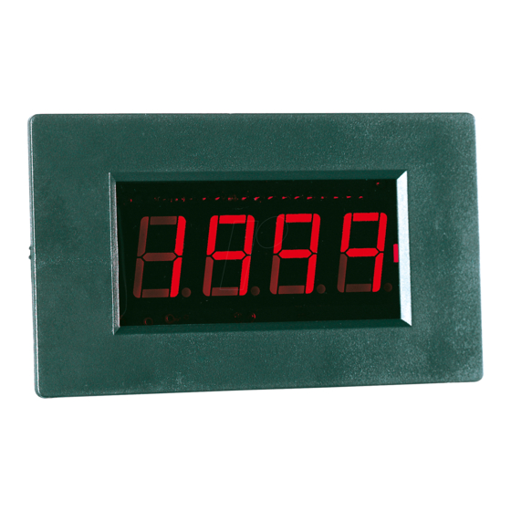
- Page 1 LDP-135 - 340 LCD / 235 - 240 LED series Bedienungsanleitung / Operation Manual Voltmeter - Module / Modules...
- Page 2 1. Allgemeines Bei diesen LCD- bzw. LED-Voltmeter-Modulen handelt es sich um 3 ½ - stellige Module, die für den Einsatz in Voltmetern und Amperemetern geeignet sind. Sie erlauben die Messung von Gleichspannungen bis max. 500 V, abhängig von der Beschaltung von Ra und Rb sowie die Messung von Gleichströmen von 0,2 mA bis max.
- Page 3 * Bei der Messung, und entsprechender Beschaltung des Moduls, von Spannungen über 30 V = 42 V oder 60 V DC muss das Modul und das System, in dem das Modul integriert ist, den relevanten Abschnitten der Vorschrift EN- 61010-1 (Sicherheitsanforderungen an elektrische Geräte Messung, Steuerung für...
- Page 4 Segmenthöhe LDP-135 LCD: 13 mm LDP-140 LCD: 13 mm LDP-235 LED: 14 mm rot LDP-240 LED: 14 mm grün LDP-335 LCD: 8 mm LDP-340 LCD: 8 mm Überbereichsanzeige “1” erscheint im Anzeigefeld Messfolge 2...3 x pro Sekunde Ω Eingangswiderstand > 100 M Genauigkeit ±...
- Page 5 Abmessungen LDP-135/140: 68,5 x 40,5 x 18 mm LDP-335/340: 47 x 20 x 16 mm LDP-235/240: 83 x 49,5 x 22 mm 4. Betrieb Vor der Inbetriebnahme muss auf eine ausreichende Isolation des Moduls und die Einhaltung der Luft- und Kriechstrecken gem.
- Page 6 umgesteckt werden. Die Widerstände sind nicht im Liefer- umfang enthalten. ACHTUNG! Vor Veränderung der Spannungsteiler (Ra und Rb), Modul unbedingt vom Mess- und Versorgungskreis (Batterie) trennen. LDP-135 / 140 LCD: Max. Erforderlicher Kommastelle Mess- Spannungsteiler spannung 200 mV Ra: offen (Lieferzustand) P3 kurzschließen 0 Ω...
- Page 7 LDP 335 / 340 LCD: Max. Erforderlicher Kommastelle Mess- Spannungsteiler spannung Ra: 0 Ω (Lieferzustand) 200 mV P3 kurzschließen Rb: offen P1 kurzschließen Ra: 9 M / Rb: 1 M P2 kurzschließen Ra: 9,9 M / Rb: 100 k P3 kurzschließen Ra: 9,99 M...
- Page 8 Shunt ( = Neben- Messbereich Kommastelle widerstand) Ω 200 µA P 3 kurzschl. Ω 2 mA P 1 kurzschl. Ω 20 mA P 2 kurzschl. Ω 200 mA P 3 kurzschl. Ω 2000 mA Achtung! Die max. Spannung im Messkreis darf 35 V DC auf keinen Fall überschreiten.
- Page 9 4.3. Schaltungsvorschläge 5. Anschlussplan LDP-135 / LDP-140 Rückansicht:...
- Page 10 LDP-235 / LDP-240 Rückansicht: zum Setzten des Dezimalpunktes LDP-335 / LDP-340 LCD Rückansicht:...
- Page 11 Letzter Stand bei Drucklegung. Technische Änderungen des Gerätes, welche dem Fortschritt dienen, vorbehalten. Hiermit bestätigen wir, dass das Gerät die in unseren Unterlagen genannten Spezifikationen erfüllt und werkseitig kalibriert geliefert wird. Eine Wiederholung der Kalibrierung nach Ablauf von 1 Jahr wird empfohlen. ® ©PeakTech 03/2019/Ho/Th/Pt/JTh -10-...
- Page 12 1. General These LCD-/LED-voltmeter modules are 3 ½ digit modules for application in Voltmeter and Amperemeter. They are suitable for measuring DC voltage up to max. 500 V, depending of the wiring of Ra and Rb. You can also measure DC current of 0.2 mA up to max.
- Page 13 * Use caution when working above 25 V AC or 35 V DC. Even such voltage poses a shock hazard. * Before you change the measuring range (another wiring of Ra and Rb) remove the probe tips from the circuit. * Measuring instruments don’t belong to children hands 3.
- Page 14 Power dissipation 1 mA DC (LDP-135/335) 30 mA DC (LDP-340) 70 mA DC (LDP-140) ca. 60…170 mA DC (LDP-235/240) Decimal point selectable with jumper Mounting holes LDP-135/140: 54,5 mm (W) x 38,8 (H) mm LDP-335/340: 43,5 mm (W) x 19,5 (H) mm LDP-235/240: 69,5 mm (W) x 46,5 (H) mm Supply voltage...
- Page 15 - 9 … 12 V DC (LDP-235 / 240 LED) to the supply input (9 V battery). Please consider the polarity. Caution! A simultaneously supply of the module and measuring of the supply voltage is not possible. Operation of several modules with same power supply is not possible (one module = one power supply, i.
- Page 16 LDP 235 / 240 LED: Max. Required voltage divider Decimal point measuring voltage 0 Ω (factory setting) 200 mV Short P3 Rb: open Short P1 M M Short P2 M Rb: 100 k Short P3 9,99 M Rb: 10 k 9,999 M...
- Page 17 Resistors Ra and Rb are ½ Watt; 0,5 % metal-foil resistors. Connect module to an external DC voltage source. The accuracy on all ranges expect 200 mV range should be adjusted with a calibrated voltage of 50% of the selected range (i. e. 100 V for 200 V range). Adjust potentiometer for equal reading of scale.
- Page 18 Caution! The max. voltage should not exceed 35 V DC in the circuit. The measuring input for current/voltage is not protected. 4.3. Recommended circuit configurations 5. Connecting diagram LDP-135 / LDP-140 Back-view: -17-...
- Page 19 LDP-235 / LDP-240 Back-view: for setting the decimal-point LDP-335 / LDP-340 LCD Back-view: for setting the decimal-point -18-...
- Page 20 We recommend to calibrate the unit again, after 1 year. ® ©PeakTech 03/2019/Ho/Th/Pt/JTh PeakTech Prüf- und Messtechnik GmbH - Gerstenstieg 4 - DE-22926 Ahrensburg / Germany +49-(0) 4102-97398-80 +49-(0) 4102-97398-99 info@peaktech.de...
Need help?
Do you have a question about the LDP-135 LCD Series and is the answer not in the manual?
Questions and answers